| Computers, Materials & Continua DOI:10.32604/cmc.2022.031173 | |
| Article |
Speed-Direction Sensing under Multiple Vehicles Scenario Using Photonic Radars
1Department of Electronics Technology, Guru Nanak Dev University, Amritsar, 143005, India
2Wireless Communication Ecosystem Research Unit, Department of Electrical Engineering, Chulalongkorn University, Bangkok, Thailand
3Department of Electronics and Communication, Guru Nanak Dev University, Regional Campus Jalandhar, India
4Department of Electrical Engineering, University of Central Punjab, Lahore, Pakistan
5Department of Electrical Engineering, College of Engineering, Taif University, Taif, Saudi Arabia
*Corresponding Author: Sushank Chaudhary. Email: sushankchaudhary@gmail.com
Received: 12 April 2022; Accepted: 31 May 2022
Abstract: Recent reports from World Health Organization (WHO) show the impact of human negligence as a serious concern for road accidents and casualties worldwide. There are number of reasons which led to this negligence; hence, need of intelligent transportation system (ITS) gains more attention from researchers worldwide. For achieving such autonomy different sensors are involved in autonomous vehicles which can sense road conditions and warn the control system about possible hazards. This work is focused on designing one such sensor system which can detect and range multiple targets under the impact of adverse atmospheric conditions. A high-speed Linear Frequency Modulated Continuous Wave (LFMCW) based Photonic Radar is proposed to detect multiple targets by integrating Mode division multiplexing (MDM). Reported results in terms of range frequency, Doppler frequency and range resolution are demonstrated using numerical simulations with the bandwidths of 1 and 4 GHz and under adverse atmospheric conditions carrying 75 dB/km of attenuation. To prove the effectiveness of the proposed photonic radar, moving targets are also demonstrated with different speed. System reported substantial range resolution of 15 cm using 1 GHz of bandwidth and 3 cm using 4 GHz of bandwidth.
Keywords: World health organization; linear frequency modulated continuous wavelength; mode division multiplexing; intelligent transportation system; photonic radar; autonomous vehicle
Ever increasing road congestion and equivalent number of road accidents have driven researchers worldwide to design autonomous vehicles to realize intelligent transportation. Heavy-duty automobiles operating at high speed rely only on drivers’ attention and any impairment such as fatigue or distraction may end up in disastrous outcomes. As per world health organization’s report, each year 1.3 million deaths and approximately 40–50 million significant injuries worldwide result due to road accidents along with considerable economic losses [1]. Autonomous vehicles thus offer the potential of a transformation in transport sector with the substantial possibility of better protection on the highway making pathway to intelligent transportation. Other factors such as enhanced social mobility to the aged, differently abled or those who cannot drive themselves due to medical conditions or any other reason will be provided via autonomous vehicles. However, before this becomes a reality, researchers must undertake and illustrate autonomous vehicles' ability to perform basic driving functions safely and reliably. Autonomous vehicles utilise a complex control system to make decision about road conditions such as congestion, route planning and efficient energy consumption etc. which rely on various sensor systems [2]. The system designer for autonomous vehicles incorporates sensor blending via merging the assets of different sensing modalities to prevail over their distinct constraints [3,4]. Many sensors such as standard Global Positioning System (GPS), cameras, ultrasound sensors and radars are currently being fused together in Avs; however, photonic radar unit has gathered attention as the heart of sensing system. As conventional radars sense radio signals, photonic radar detects echoes from optical-frequency laser illumination to produce long-range and high-resolution point shadow consistent to the location and reflectivity factor of loads of points in the neighboring atmosphere. Because of narrow beam width of optical waves, photonic radar can detect and characterize considerably tinier objects than conventional radars, which is important for navigating next to walkers, bikers, and other possible threats on the roads. Factors such as cost, maximum operational range, processing requirements, operational power (with respect to human safety), line of sight, longitudinal and transverse resolution, immunity towards ambient light source and atmospheric fluctuations are considered essential for consistent real-time performance of any sensor system used in AVs [4,5]. Some of mentioned issues are regulated partially via production and hardware limits like the quality and capability of light sources and responsivity of photodiodes. These factors can be enhanced through continuous investment and improvement in the end-product. However, one of the critical features of sensor employed in AVs is providing maximum detection range as timely identification of a probable threat provides the automobile extra time to take decisions besides avoiding collision, and this cannot be realized alone with the hardware. Photonic radars work in free space and suffer from various atmospheric variations. Free Space Optics (FSO) communication system is well established and various schemes such as multiplexing of wavelength, intensity and polarization have been demonstrated to improve its capacity [6–9]. One such technique is the use of Mode Division Multiplexing (MDM) in which incongruent channels are multiplexed together. The use of MDM technique results in enhancing capacity of system and providing security against physical layer attacks [10]. Many researchers have explored the applications of MDM in FSO system in recent year. The use of MDM is still to be reported in radars and thus we propose the use of MDM in capacity enhancement of photonic radars. As photonic radars will be operating in the free space environments, selection of frequency is crucial. Recently, researchers have proposed different methods to attain high-resolution detection using photonic radars. In [11], a 4 × 8 Multiple-Input Multiple-Output (MIMO) photonic radar is demonstrated with each channel having orthogonal linearly frequency modulated signal generated by heterodyne scheme and 2 GHz bandwidth resulted in range resolution of 7.5 cm. Earlier direct detection scheme-based photonic radar is proposed with a range ability of 750 m under adverse atmospheric conditions [12] with minimum input power requirement. Another study [13] demonstrates the use of photonic radar with hexacopter in detecting drone movement proposed with a detection range of 2700 m experimentally. The implication of different configuration of frequency modulated continuous wave (FMCW) based photonic radar and its advantages are discussed in [14]. In [15] researchers studied the FMCW-based photonic radar in coherent detection with operation bandwidth of 600 MHz. Authors [16]discussed the impact of bandwidth variations on the range resolution of photonic radar. Another study [17] discusses the Doppler rage measurement using polarization division multiplexing based FMCW photonic radar.
In the present work, we have considered a complex scenario where four moving targets are detected using FMCW-based photonic radar in coherent detection scheme. The targets are assumed to be moving at different speed and accordingly blue and red shifts are calculated. The targets are also subject to adverse atmospheric conditions and impact of these conditions upon detection and ranging is observed and compared by utilizing different wavelengths that is 1 and 4 GHz. The major impact of MDM enabled FMCW based photonic radar is
• Minimal dimensions of trans-receiver (i.e., 5 and 15 mm respectively) resulting in compact and cost effective design.
• Ability to distinguish closely spaced targets (Higher range resolution of 3 cm).
• All weather detection (can withstand heavy turbulences of 75 dB/Km)
Autonomous vehicles rely on the effectiveness or ability of a sensor to distinguish between various targets and road conditions. Thus, range resolution
where c is speed of light and B is operational bandwidth. Thus, it is evident from Eq. (1) that higher the bandwidth more will be the ability of radar to distinguish between closely spaced multiple targets. Formerly, operation frequency used for LiDAR operation was 24 GHz with a bandwidth of 250 MHz also known as ISM band but due to smaller bandwidth it was not suitable for future autonomous vehicle applications [19].
Alternatively, state-of-the-art 77 GHz band utilised by short range radar (SRR) offers 4 GHz of bandwidth is a much better option in terms of range resolution and high equivalent isotropic radiated power (EIRP). The 4 GHz bandwidth offered by SRR band offers three times improved velocity resolution and twenty times enhanced range resolution compared to the ISM band. The present work is based upon Doppler-effect in which targets are detected and ranged. In traditional radars, radio signal is transmitted over free space towards the target and reflected echoes from the targets are collected to extract the information of target in respect of its range and speed. As harmonic distortions related to μ-wave band in case of traditional radars affect the efficiency of system, the same can be reduced by modulating radio signal over optical carrier. Furthermore, beam divergence in traditional radar is very large due to its high aperture diameter while optical signal offers small beam divergence due to narrow line-width of laser source making photonic radar more suitable for autonomous vehicles [20]. The received echo from the target is known as range frequency fr and is a function of bandwidth B, distance R between target and radar-equipped vehicle and sweep time TS which can be mathematically expressed as in Eq. (2):
where c is the speed of light in free space. For detecting multiple targets, we have applied mode division multiplexing (MDM) scheme. The system is subject to various atmospheric conditions in terms of attenuation and performance is investigated. The system is further used to detect Doppler shift and to measure the vehicle velocity. The system is then tested for range resolution
Fig. 1 represents the basic block diagram of proposed frequency modulated continuous wave coherent detection mode division multiplexing-based photonic radar. It can be observed that four targets are considered for four individual transmitters each operating at single wavelength of 1550 nm. Each transmitter consists of three parts: first is linear frequency modulator (LFM) section to generate microwave band FM signal, second is optical source and corresponding mode generator, and third is modulator section to modulate LFM signal over optical signal.
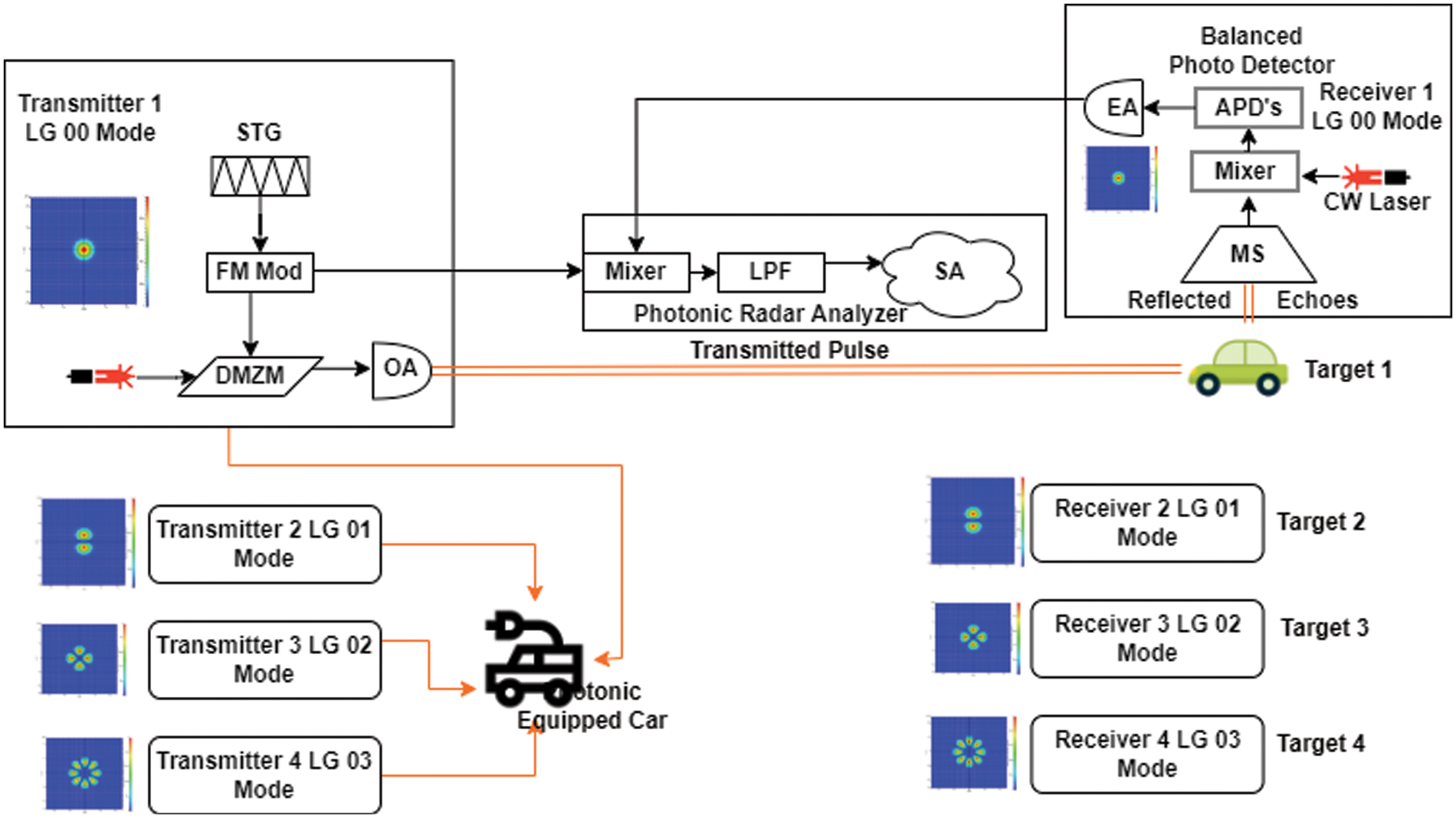
Figure 1: Graphic illustration of proposed MDM multiplexed Photonic radar with multiple target (four) detection
Note: STG-Saw Tooth Generator, FM-Frequency modulator, DMZM-Dual port Mech Zhender Modulator, MS-Mode Selector, APD-Avalanche Photo Diode, OA-Optical Amplifier, EA-Electrical Amplifier, LPF-Low Pass Filter, SA-Signal Analyzer.
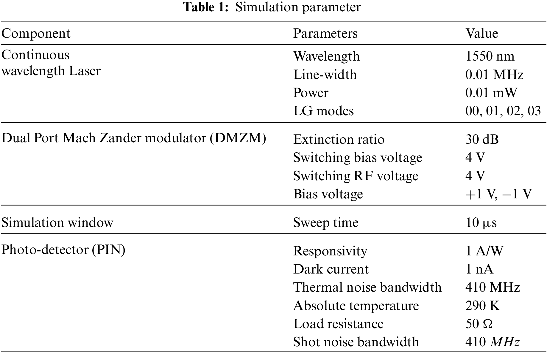
In LFM section, saw-tooth-generated signal is frequency modulated via LFM modulator with 77 GHz of operating frequency and two bandwidths of 1 and 4 GHz. The splitter is employed to split this output signal into two parts; one is sent towards modulator and other towards receiver as a reference signal. The optical source here used is continuous wave laser with input power of −10 dBm (0.1 mW) and operating wavelength of 1550 nm. The generated optical signal is subjected into the mode generator which attaches transverse mode profiles to the input signal. We have utilized Laguerre-Gaussian (LG) profile in this work, which is described as in Eq. (3) [21]:
where
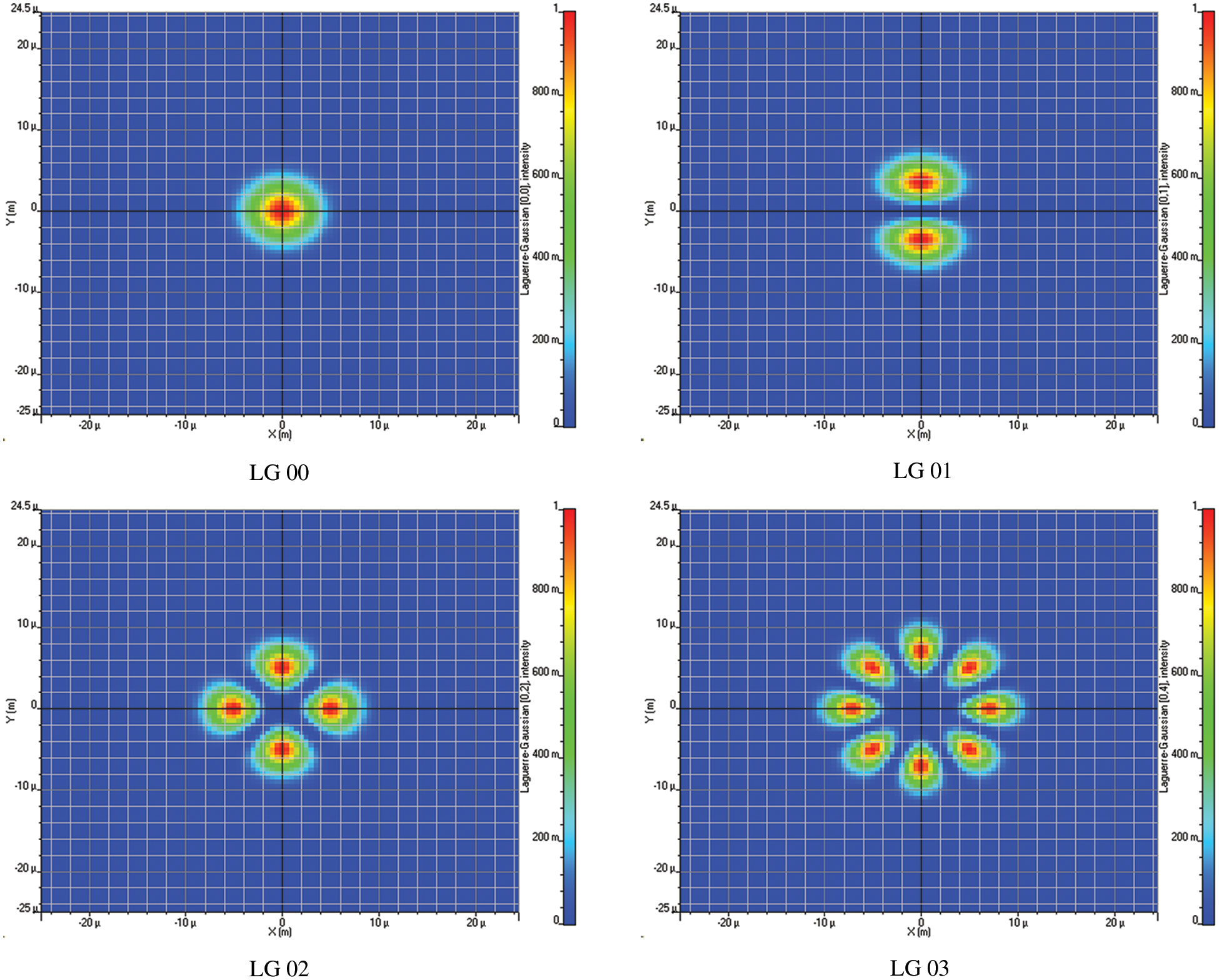
Figure 2: Mode profiles of LG modes
This transverse optical signal acts as a carrier signal to the LFM signal and modulated using dual port Mach Zhander modulator (DMZM). The output of the DMZM is represented as E(t) mathematically as in Eq. (4) [22]:
where Ein (t) is input signal strength from optical source, insertion loss is given as IL,
where R is operating range, θ is the beam divergence; dT & dR are transmitter and receiver aperture diameters respectively and α represents atmospheric turbulences. For AVs, fog and rain are considered as key parameters that restrict the operational efficiency in terms of detection and ranging. Fog appears to be more destructive than rainfall as wavelength used in optical communication is smaller than droplets. Rainfall attenuation is given by Kim model as given in Eq. (6) [24]:
where k and α are variables dependent upon droplet size, frequency and temperature and computed using Marshall Palmer distribution while ro signifies the quantity of rain in mm/hr. For calculating fog attenuation Mie scattering model is used which is given as in Eq. (7) [25]:
where V is visibility in kilometres,
where D refers to the receiver aperture diameter, ρt a target reflectivity, At target area, τopt the optical transmission loss, τatm the atmospheric loss, Aill illuminated target area and R refers to the target range. While output signal from the low pass filter also known as beat signal (
where
The results obtained from the modelling of proposed MDM-enabled FMCW-based photonic radars for detection and ranging of multiple targets are presented in this section. First, the proposed system is tested for clear weather conditions with stationary targets in which attenuation from the atmosphere is assumed to be 0.2 dB/Km. The system is also tested for the different bandwidths in clear atmospheric conditions. Fig. 3 presents the clear weather conditions detection of multiple targets.
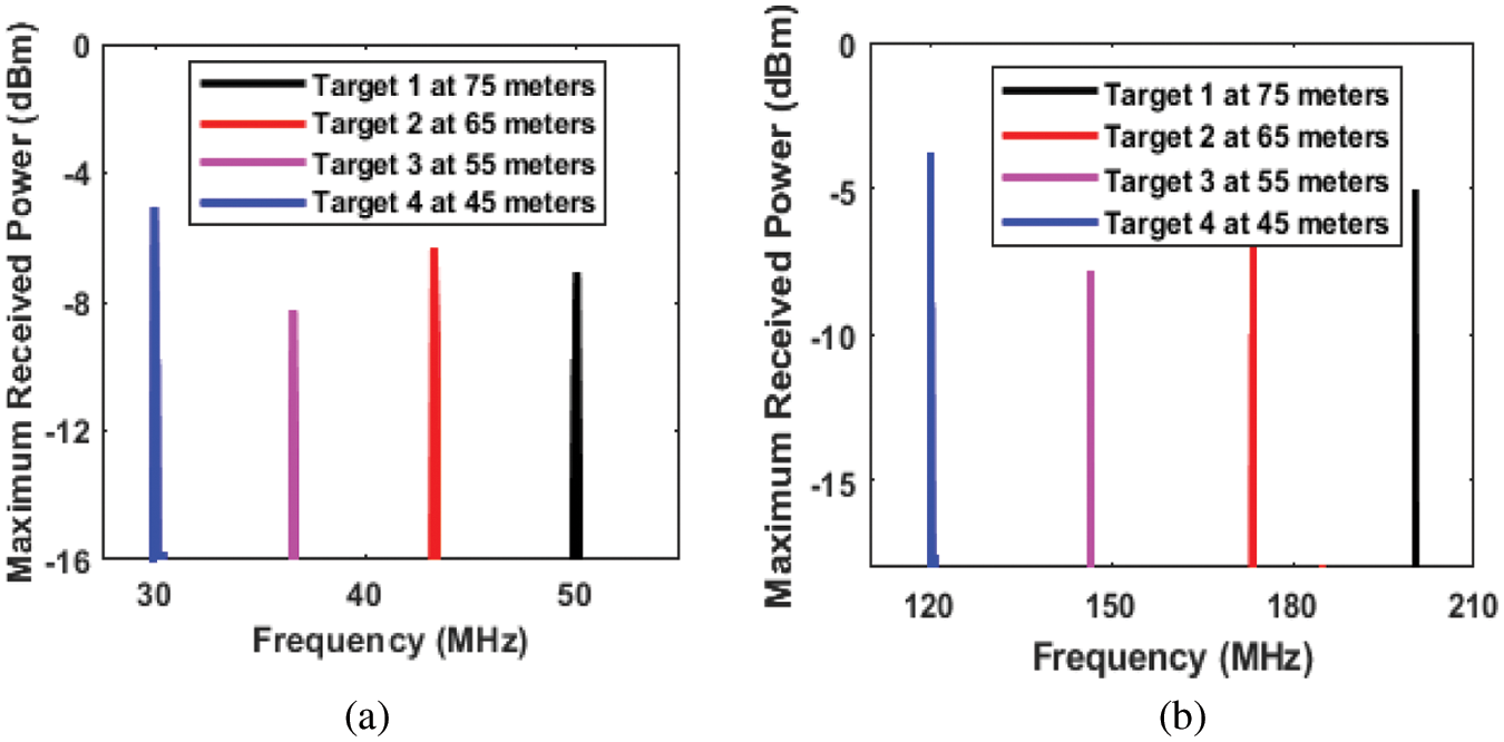
Figure 3: Multiple Target detection under clear atmospheric conditions (a) at 1 GHz bandwidth and (b) at 4 GHz bandwidth
In this work, four different targets are assumed to be located at different distance from the photonic radar such that target 1 is at 75 m, target 2 at 65 m, target 3 at 55 m and target 4 at 45 m. Fig. 3a depicts detection with 1 GHz bandwidth while detection with 4 GHz bandwidth is presented by Fig. 3b. At 1 GHz bandwidth, the range frequency of received echo is observed at 50 MHz for target 1, at 43.33 MHz for target 2, at 36.6 MHz for target 3 and at 30 MHz for target 4. Similarly, with bandwidth of 4 GHz, the range frequency of received echo is observed at 200 MHz for target 1, at 172.90 MHz for target2, at 146.31 MHz for target 3 and at 119.7 MHz for target 4. The mathematically calculated values of range frequency using Eq. (2) with range and bandwidth parameter as prescribed above matches with the simulation values. Hence, it may be concluded that the proposed system is capable of error-free detection of multiple targets. Fig. 4 depicts the impact of atmospheric turbulences.
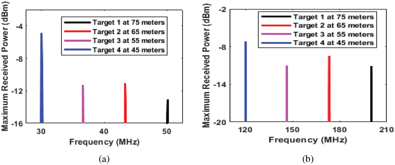
Figure 4: Multiple Target detection under heavy attenuation of 75 dB/Km atmospheric conditions (a) at 1 GHz bandwidth and (b) at 4 GHz bandwidth
The system has been tested for varying attenuation from 0 to 75 dB/km and reported results show the successful reception at maximum attenuation of 75 dB/km in Fig. 4 with stationary targets. Fig. 4a depicts the impact of atmospheric attenuation on targets with 1 GHz of bandwidth. It may be noted that target 4 has least impact in terms of maximum received power as compared to target 1, target 2 and target 3. Likewise, successful detection of all the targets is reported in 4 GHz bandwidth in Fig. 4b. It may also be noted that the range frequency reported again is similar to that of mathematically calculated values using Eq. (2). Hence, it may be concluded that the error-free detection is reported using the proposed model.
As coherent detection scheme is used to analyse intensity as well as phase of the target; hence, the proposed system is further tested for analysing moving targets. For the simulation purpose, targets are supposed to be moving at different speed but the range from the photonic radar is kept the same. That is, target 1 is assumed to be at 75 m and moving with a speed of 20 Km/hr. Similarly, target 2 is assumed to be at 65 m and moving with speed 32 KM/hr, target 3 at 55 m and moving with a speed of 36 Km/hr and target 4 is assumed to be 45 m with velocity of 50 Km/hr. Corresponding Doppler frequency for target 1 is calculated as 7 Mhz, for target 2 it is calculated as 11.5 MHz, for target 3 doppler frequency is 12.9 MHz and for target 4 doppler frequency is calculated as 17.91 MHz. As Doppler shift is dependent upon the targets direction such that if the target is approaching towards the photonic radar, the range frequency will decrease by the amount of Doppler frequency (i.e., fr – fd) and the target will be moving away from the photonic radar then range frequency will be added up by the amount of Doppler frequency (i.e., fr + fd).
Fig. 5 depicts the moving targets detection having different speed and range from photonic radar. For simulation purpose both the scenarios has been considered that is target approaching the photonic radar as fr – fd and target going away from the photonic radar as fr + fd. The range frequency peaks obtained in the numerical simulation results equals the mathematically calculated value in both the cases in Figs. 5a and 5b. In Fig. 5a peaks observed for target 1 when target is moving away from photonic radar is at 57 MHz and when target is moving towards the photonic radar peak is observed at 43 MHz as highlighted in black colour in Fig. 5a. Similarly, for target 2 when target is moving away from photonic radar peak is at 54.8 MHz and when target is moving towards the photonic radar peak is observed at 31.8 MHz ass highlighted in red colour, for target 3 when target is moving away from photonic radar peak is at 49.5 MHz and when target is moving towards the photonic radar peak is observed at 23.76 MHz as highlighted in pink colour and for target 4 when target is moving away from photonic radar peak is at 47.9 MHz and when target is moving towards the photonic radar peak is observed at 12.10 MHz as highlighted in blue colour in Fig. 5a. Likewise, in Fig. 5b peaks observed for target 1 when target is moving away from photonic radar is at 207 MHz and when target is moving towards the photonic radar peak is observed at 193 MHz as highlighted in black colour in Fig. 5b. Similarly, for target 2 when target is moving away from photonic radar peak is at 184.5 MHz and when target is moving towards the photonic radar peak is observed at 161.40 MHz as highlighted in red colour, for target 3 when target is moving away from photonic radar peak is at 159.2 MHz and when target is moving towards the photonic radar peak is observed at 133.40 MHz as highlighted in pink colour and for target 4 when target is moving away from photonic radar peak is at 137.60 MHz and when target is moving towards the photonic radar peak is observed at 101.8 MHz as highlighted in blue colour in Fig. 5b.
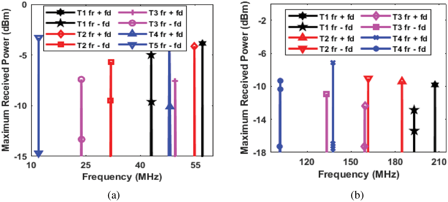
Figure 5: Multiple moving target detection (a) at 1 GHz bandwidth and (b) at 4 GHz bandwidth. T1 is target 1 at 75 m with speed 20 KM/hr; T2 is target 2 at 65 m with speed 32 Km/hr; T3 is target 3 at 55 m with speed 36 Km/hr and T4 is target 4 at 45 m with speed 50 Km/hr
Lastly, the system is tested for the ability to distinguish between closely spaced targets also termed as range resolution and as given in Eq. (1) the impact of varying bandwidth is also proved. Fig. 6 illustrates the impact of bandwidth on the range resolution of the photonic radar.
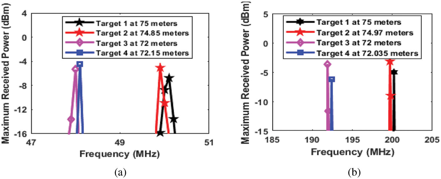
Figure 6: Range resolution of proposed photonic radar (a) at 1 GHz bandwidth and (b) at 4 GHz bandwidth
In Fig. 6a, targets are placed 15 cm apart from each other such that target 1 is at 75 m and target 2 is at 74.85 m while target 3 is at 72 m and target 4 is at 72.15 m. The individual and non-overlapping peaks obtained in numerical simulations depict successful detection of these targets which also proves the range resolution of proposed system to be 15 cm and is exactly the same as calculated mathematically using Eq. (1) at bandwidth of 1 GHz. Further, Fig. 6b illustrates the targets placed at 3 cm distance from each other such that target 1 is placed at 75 m and target 2 is at 74.97 m while target 3 is placed at 72 m and target 4 is placed at 72.035 m. The individual and non-overlapping peaks obtained in numerical simulations depicts successful detection of these targets which also proves the range resolution of proposed system to be 3 and 3.5 cm which is further improved then theoretically value calculated mathematically using Eq. (1) at bandwidth of 4 GHz. The results also verified that with increasing operational bandwidth, the resolution of the photonic radar improves.
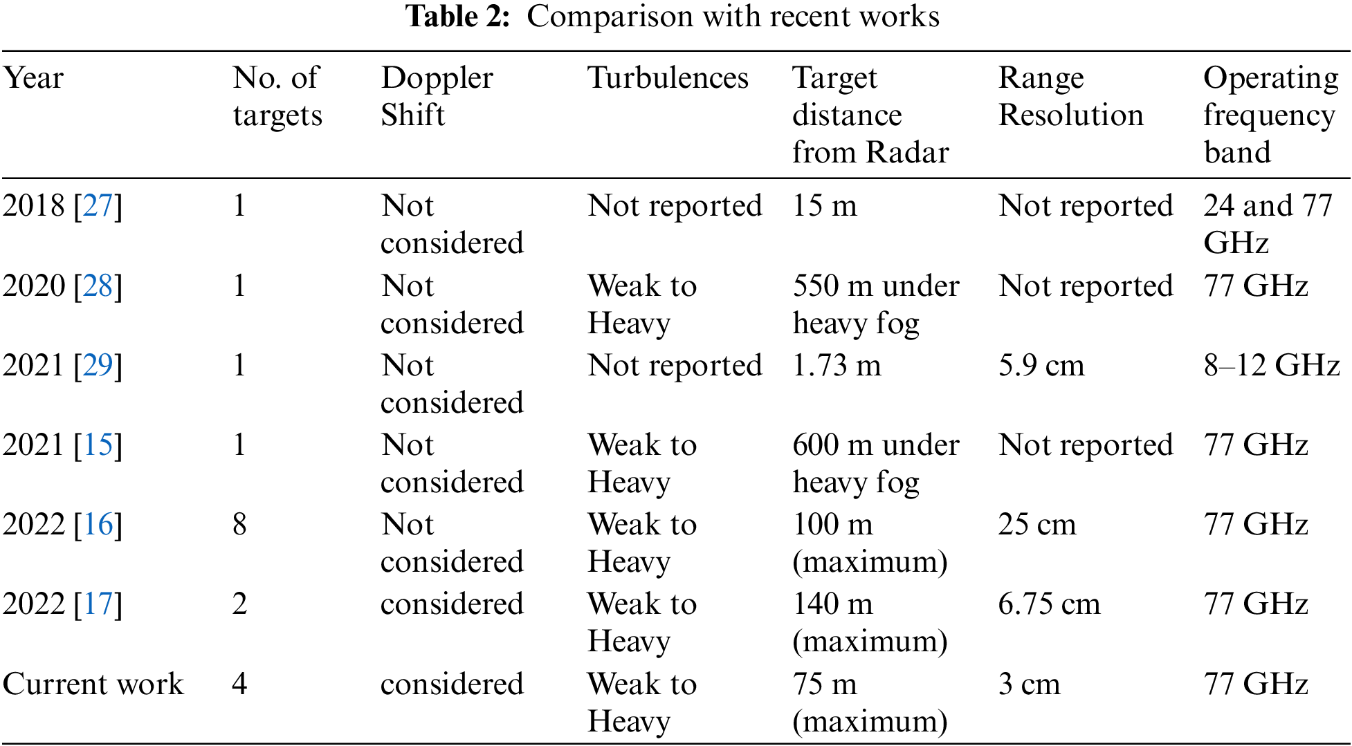
Tab. 2 distinguishes between previously reported works and our work in terms of Doppler frequency detection, range, targets, turbulences and range resolution.
In this paper, we have designed photonic radar for intelligent transportation system by employing mode division multiplexing technique to detect four individual targets. Numerical simulation for the proposed system is carried out to analyse the impact of atmospheric conditions. The reported results show successful detection of all the four targets with range frequency of 50, 43.3, 36.6 and 30 MHz for target 1, 2 ,3 and 4 respectively with bandwidth of 1 GHz and range frequency of 200, 172.90, 146.3 and 119.70 MHz for target 1, 2 ,3 and 4 respectively with bandwidth of 4 GHz. The system is further tested under atmospheric conditions and reported results under high attenuation of 75 dB/km depict successful detection as well as validation of proposed system. Further, the system is tested for analysing speed and direction of the targets as well as range resolution of the proposed photonic radar system and resulted in 15 cm resolution with 1 GHz bandwidth wile resolution of 3 cm with 4 GHz of bandwidth. All the numerical simulation results obtained contents with the mathematically obtained results and validates the proposed system. Further, extension of the proposed model can be achieved by real-time test-beds as well as introducing machine learning algorithms to take decision based upon the inputs of the photonic radar sensor.
Funding Statement: This research project is supported by the Second Century Fund (C2F), Chulalongkorn University, Thailand. This research work is also funded by TSRI Fund (CU_FRB640001_01_21_8). The authors also would like to thank Taif University Researchers supporting project number (TURSP-2020/228), Taif University, Taif, Saudi Arabia.
Conflicts of Interest: The authors declare that they have no conflicts of interest to report regarding the present study.
References
1. W. H. Organization, Road traffic injuries, 2021. [Google Scholar]
2. J. Rapp, J. Tachella, Y. Altmann, S. McLaughlin and V. K. Goyal, “Advances in single-photon lidar for autonomous vehicles: Working principles, challenges, and recent advances,” IEEE Signal Processing Magazine, vol. 37, no. 4, pp. 62–71, 2020. [Google Scholar]
3. R. O. Chavez-Garcia and O. Aycard, “Multiple sensor fusion and classification for moving object detection and tracking,” IEEE Transactions on Intelligent Transportation Systems, vol. 17, no. 2, pp. 525–534, 2015. [Google Scholar]
4. K. Bengler, K. Dietmayer, B. Farber, M. Maurer, C. Stiller et al., “Three decades of driver assistance systems: Review and future perspectives,” IEEE Intelligent Transportation Systems Magazine, vol. 6, no. 4, pp. 6–22, 2014. [Google Scholar]
5. B. Behroozpour, P. A. Sandborn, M. C. Wu and B. E. Boser, “Lidar system architectures and circuits,” IEEE Communications Magazine, vol. 55, no. 10, pp. 135–142, 2017. [Google Scholar]
6. S. Chaudhary and A. Amphawan, “Solid core PCF-based mode selector for MDM-Ro-FSO transmission systems,” Photonic Network Communications, vol. 36, no. 2, pp. 263–271, 2018. [Google Scholar]
7. A. Sharma, J. Malhotra, S. Chaudhary and V. Thappa, “Analysis of 2 × 10 Gbps MDM enabled inter satellite optical wireless communication under the impact of pointing errors,” Optik, vol. 227, no. 1, pp. 165250, 2021. [Google Scholar]
8. S. Chaudhary, L. Wuttisittikulkij, J. Nebhen, X. Tang, M. Saadi et al., “Hybrid MDM-PDM based Ro-FSO system for broadband services by incorporating donut modes under diverse weather conditions,” Frontiers in Physics, vol. 9, pp. 217, 2021. [Google Scholar]
9. K. H. Shakthi Murugan, A. Sharma and J. Malhotra, “Performance analysis of 80 Gbps Ro-FSO system by incorporating hybrid WDM-MDM scheme,” Optical and Quantum Electronics, vol. 52, pp. 505, 2020. [Google Scholar]
10. S. Chaudhary and A. Amphawan, “Selective excitation of LG 00, LG 01, and LG 02 modes by a solid core PCF based mode selector in MDM-Ro-FSO transmission systems,” Laser Physics, vol. 28, no. 7, pp. 075106, 2018. [Google Scholar]
11. B. Gao, F. Zhang, G. Sun, Y. Xiang and S. Pan, “Microwave photonic MIMO radar for high-resolution imaging,” Journal of Lightwave Technology, vol. 39, no. 24, pp. 7726–7733, 2021. [Google Scholar]
12. A. Sharma, S. Chaudhary, J. Malhotra, M. Saadi, S. A. Otaibi et al., “A cost-effective photonic radar under adverse weather conditions for autonomous vehicles by incorporating frequency modulated direct detection scheme,” Frontiers in Physics, vol. 9, pp. 467, 2021. [Google Scholar]
13. Y. Bae, J. Shin, S. G. Lee and H. Kim, “Field experiment of photonic radar for low-RCS target detection and high-resolution image acquisition,” IEEE Access, vol. 9, pp. 63559–63566, 2021. [Google Scholar]
14. A. Sharma and J. Malhotra, “Simulative investigation of FMCW based optical photonic radar and its different configurations,” Optical and Quantum Electronics, vol. 54, no. 4, pp. 233, 2022. [Google Scholar]
15. S. Chaudhary, L. Wuttisittikulkij, M. Saadi, A. Sharma, S. Al Otaibi et al., “Coherent detection-based photonic radar for autonomous vehicles under diverse weather conditions,” PLOS ONE, vol. 16, no. 11, pp. e0259438, 2021. [Google Scholar]
16. A. Sharma, S. Chaudhary, J. Malhotra, A. Parnianifard, S. Kumar et al., “Impact of bandwidth on range resolution of multiple targets using photonic radar,” IEEE Access, vol. 10, pp. 47618–47627, 2022. [Google Scholar]
17. A. Sharma, S. Chaudhary, J. Malhotra, A. Parnianifard and L. Wuttisittikulkij, “Measurement of target range and doppler shift by incorporating PDM-enabled FMCW-based photonic radar,” Optik, vol. 262, pp. 169191, 2022. [Google Scholar]
18. F. Zhang, Q. Guo and S. Pan, “Photonics-based real-time ultra-high-range-resolution radar with broadband signal generation and processing,” Scientific Reports, vol. 7, no. 1, pp. 1–8, 2017. [Google Scholar]
19. K. Ramasubramanian and K. Ramaiah, “Moving from legacy 24 GHz to state-of-the-art 77-GHz radar,” ATZelektronik Worldwide, vol. 13, no. 3, pp. 46–49, 2018. [Google Scholar]
20. S. Piatek and J. Li, “A photonics guide to the autonomous vehicle market,” Laser Focus with Fiberoptic Technology, vol. 53, pp. 28–31, 2017. [Google Scholar]
21. A. A. GHATAK, A. Ghatak, K. Thyagarajan and K. Thyagarajan, “Modes in plannar waveguides,” in An Introduction to Fiber Optics, 1st ed., vol. 1, UK: Cambridge university press, 1998. [Google Scholar]
22. A. H. Elghandour and C. D. Ren, “Modeling and comparative study of various detection techniques for FMCW LIDAR using optisystem,” in Int. Symp. on Photoelectronic Detection and Imaging 2013: Laser Sensing and Imaging and Applications, Beijing, China, pp. 890529, 2013. [Google Scholar]
23. S. Chaudhary and A. Amphawan, “High-speed MDM-Ro-FSO system by incorporating spiral-phased Hermite Gaussian modes,” Photonic Network Communications, vol. 35, no. 3, pp. 374–380, 2018. [Google Scholar]
24. F. Rashidi, J. He and L. Chen, “Spectrum slicing WDM for FSO communication systems under the heavy rain weather,” Optics Communications, vol. 387, no. 2014, pp. 296–302, 2017. [Google Scholar]
25. R. Olsen, D. Rogers and D. Hodge, “The aRbrelation in the calculation of rain attenuation,” IEEE Transactions on Antennas and Propagation, vol. 26, no. 2, pp. 318–329, 1978. [Google Scholar]
26. M. S. Awan, L. Csurgai-Horváth, S. S. Muhammad, E. Leitgeb, F. Nadeem et al., “Characterization of fog and snow attenuations for free-space optical propagation,” Journal of Communication, vol. 4, pp. 533–545, 2009. [Google Scholar]
27. G. Serafino, F. Amato, S. Maresca, L. Lembo, P. Ghelfi et al., “Photonic approach for on-board and ground radars in automotive applications,” IET Radar, Sonar & Navigation, vol. 12, no. 10, pp. 1179–1186, 2018. [Google Scholar]
28. V. Sharma and S. Sergeyev, “Range detection assessment of photonic radar under adverse weather perceptions,” Optics Communications, vol. 472, no. 5, pp. 125891, 2020. [Google Scholar]
29. D. Liang, L. Jiang and Y. Chen, “Multi-functional microwave Photonic Radar system for simultaneous distance and velocity measurement and high-resolution microwave imaging,” Journal of Lightwave Technology, vol. 39, no. 20, pp. 6470–6478, 2021. [Google Scholar]
 | This work is licensed under a Creative Commons Attribution 4.0 International License, which permits unrestricted use, distribution, and reproduction in any medium, provided the original work is properly cited. |