| Computers, Materials & Continua DOI:10.32604/cmc.2022.031291 | |
| Article |
Outage Probability Analysis of Free Space Communication System Using Diversity Combining Techniques
Department of Electrical Engineering, The University of Lahore, Lahore, 54000, Pakistan
*Corresponding Author: Hasnain Kashif. Email: dee01153001@student.uol.edu.pk
Received: 14 April 2022; Accepted: 10 June 2022
Abstract: Recently, free space optical (FSO) communication is gaining much attention towards the research community. The reason for this attention is the promises of high data-rate, license-free deployment, and non-interfering links. It can, however, give rise to major system difficulties concerning alignment and atmospheric turbulence. FSO is the degradation in the signal quality because of atmospheric channel impairments and conditions. The worst effect is due to fog particles. Though, Radio Frequency (RF) links are able to transmit the data in foggy conditions but not in rain. To overcome these issues related to both the FSO and RF links. A free space communication system (FSCS) is proposed, in which the hybrid technology is based on the individual FSO and RF channel. FSCS is a capable solution to overcome the difficulties of the existing systems (FSO and RF) as well as to enhance the overall link reliability and availability. In this paper, FSCS is investigated in terms of performance throughput (i.e., outage probability and bit-error-rate (BER)) by implementing the receive diversity combining techniques. An analysis of the outage probability of the proposed system along with the individual FSO and RF system is developed. Simulation results are presented to support the analysis. It is shown that the proposed system outperforms the individual FSO and RF system and gives a power gain of 3dB over a distinct number of receive antennas.
Keywords: Atmospheric turbulence; free space communication system; power management; signal independent noise; line of sight
In the recent era, free space optical (FSO) communication systems are taken into consideration as an auspicious answer to the numerous applications consuming high bandwidth. The primary benefits of FSO include high-capacity and unlicensed spectrum. Owing to the provision of a huge variety of broadband, systems 5 with low priced implementation and less power consumption are preferred. Presently, the trade-off is twofold but the unknown channel conditions and crucial pointing issues, make optical systems less stable than the conventional radio-frequency (RF) communication systems [1,2]. The FSO system implementation has some crucial difficulties including-atmospheric turbulence, degradation in link quality and Line of sight (LOS) [3]. Along with the inherited benefits of the optical spectrum though it suffers from various drawbacks when 10 utilizing it over a long distance employing the multiplexing techniques. These drawbacks include modal dispersion, linear coupling (referred to as cross-talk), and non-linear effects [4]. Due to the presence of these drawbacks, the optical received signal gets and is attenuated by turbulence, mis-alignment and divergence. To overcome these issues, various techniques have been presented in [5–9]. The most prominent are the accurate pointing, acquisition and tracking, digital signal processing, adaptive optics and modifying transmitted beams are employed, which support minimizing the effect of modal coupling and cross-talk. Even in the era of machine learning, neural network models are also recommended to limit such drawbacks of optical channel transmission [10,11]. Much research works on wireless sensor networks, which have limited energy and transmission capacity [12–20].
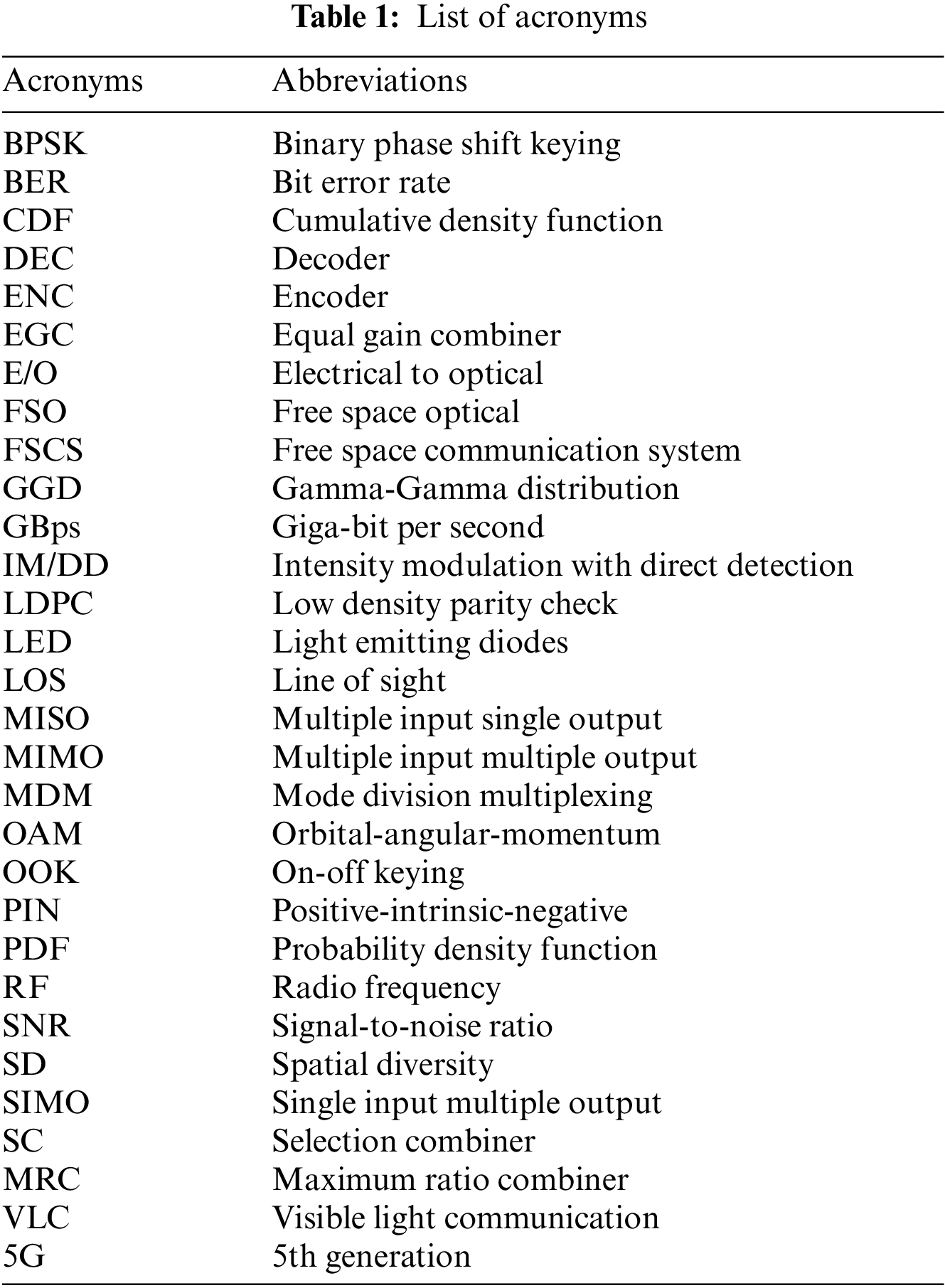
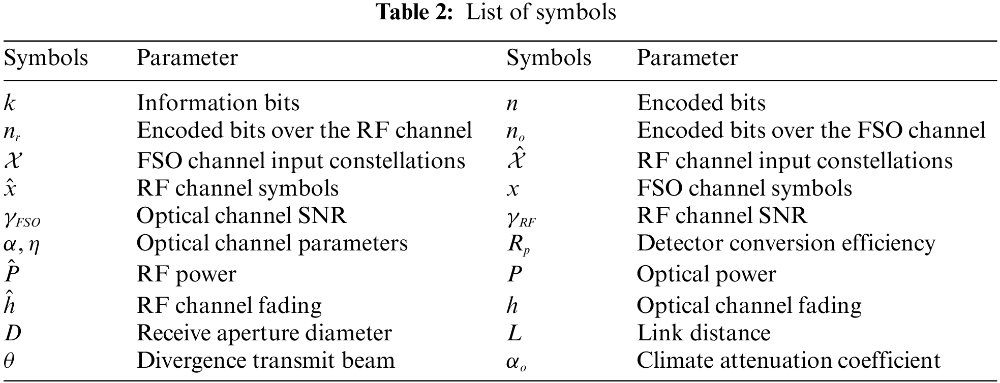
To further improve the capacity of the optical channel, it is recommended to employ an optical system carrying multiple optical beams and exploit the multiplexing technique i.e., mode division multiplexing (MDM), orbital-angular-momentum (OAM) multiplexing [21–25]. Implementing the MDM along with the OAM multiplexing, immensely raises the channel capacity of the optical links adding more difficulty for the eavesdropper. Also, Luminescent solar concentrators are suggested to improve the optical gain in case of visible light communications. A complete list of acronyms and symbols is provided in Tabs. 1 and 2 respectively.
Overall performance degrading components in the FSO systems because mainly at large distances are the induced fading of disturbances or turbulence occurrences [26]. For the FSO systems, typical decay can last milliseconds and it operates at the rate of several gigabits per seconds (GBps). As a result, a single fade can bring about the lack of a massive variety of serial bits. Researchers investigating the diversity techniques such as channel coding [27], advanced sequence detection techniques [28] and spatial diversity [29–32] to 30 overcome the difficulties of the FSO systems. The spatial diversity (SD) is most prominent due to the lower computational complexity. The main purpose is to reduce the computational complexity by using the combining techniques. Multiple transmission and reception patterns are exploited to employ the diversity combining techniques, which are well established in the RF communication systems. The same can be done in FSO systems and the detailed investigation to be carried out. In [30,31], authors have presented the outage probability analysis over the coherent FSO system by employing the receive diversity schemes. The focus was on the spatial selectivity of associative receptors that minimize the effect of background irradiation.
Diversity combining technique is broadly applicable to enhance the overall performance of wireless communication systems [29–31]. The diversity technique is suggested for mitigating the fading induced by the atmospheric turbulence [33,34]. Mostly the three types of spatial diversity, which are single input multiple outputs (SIMO), multiple inputs single output (MISO) and multiple inputs multiple outputs (MIMO) have been investigated [35,36] Diversity combining technique using multiple lasers and apertures to mitigate the fading effects is presented in [36]. Diversity combing can be implemented either on the transmitter or the receiver side. The receive diversity is more practical in mobile communication systems, since the transmitter has several limitations such as it cannot deserve considerable power consumption and processing complexity. Receive diversity combining technique collects numerous copies of the transmitted signal at the receiver, which are encountered by the distinct fading channels. The cumulative copies of the received signal are exploited to retrieve the transmitted signal [37]. The well-known combiners are the selection combiner (SC), maximum ratio combiner (MRC) and equal gain combiner (EGC) [38].
Researchers are developing a major communication technology by investigating the exploitation of radio links to compensate for system instability and name it a hybrid FSO-RF link. The research community started working on the hybrid system to improve the throughput of optical communications by exploiting the advantages of both communication systems [39–41]. In [42], the transmission over the hybrid FSO-mmW channel is considered to be more secure. In [43], authors developed a practical demonstration of hybrid transmission and claimed the overall performance with better connectivity and speed. In [3], the authors pragmatically claim that the individual optical channel can achieve 99.999% availability over a distance of 140m, while the hybrid system efficiently maximizes the connectivity distance. The aim of the hybrid FSO-RF system is to send the same signal copies concurrently over both channels and merge the received signals by exploiting the receive diversity combining technique. The combining is possible because both of the channels show compatible features to atmospheric and weather conditions whereas the radio channel is not prone to scintillation or snow and fog as the case of the FSO link, but rather to dense rain [44]. In [45,46], the researchers investigated that parallel optical-radio communication is a promising technology that exploits the complementary benefits of optical and radio link (i.e., robustness and high data rate). It is well known that although RF communications have a low risk of link failure, beam-directivity lags far behind that of FSO communications. Hence, most research on the hybrid FSO-RF systems assume a link-distance of no greater than a few kilometers to maximize the merits of additional RF links [47]. It is important that all the above-mentioned studies never focus on the optimization of the hybrid FSO-RF systems using the receive diversity combining techniques.
In the proposed method, the outage probability and system performance in terms of bit error rate (BER) have been optimized and analyzed. Free space communication system (FSCS) is deployed to significantly improve as well as reducing the total power consumption requirement under the induced atmospheric turbulence regime. It is likewise derived from the closed form of outage probability expression for the FSCS. In both RF and FSO links, in which SC and MRC combining techniques are implemented. In the FSO system, intensity modulation and direct detection (IM/DD) is employed. In FSCS, the advantages of combining both the FSO and RF links are the high data rate, and more secure and reliable links. On the other hand, FSCS can support the receiver in order to make a nice selection via the means of combining different copies of the original signal received from the channel and to enhance the system overall performance. Following are the main contributions of the proposed research;
• A novel hybrid system having single encoder and decoder is proposed. The benefits of proposing single encoder and decoder are as: cost effective system and no synchronization issue.
• To improve the performance of the proposed communication system, we develop a diversity algorithm, which exploits either of the diversity combining schemes (SC or MRC) and selects the best optimum.
• We develop a comparison between the single links (RF and FSO) and hybrid link and provide the simulation results.
2.1 Free Space Communication System (FSCS)
The proposed FSCS, where FSO and RF links deliver reliable transmission in outdoor wireless environments for real time mission and critical traffic. A typical block diagram of the proposed FSCS using the receive diversity combining techniques is shown in Fig. 1. Transmitter, receiver and channel are the major components of FSCS. FSCS includes parallel channels of FSO and RF with one encoder, which is used to reduce the implementation cost and minimize the computational complexity. The k-bits are encoded using the low-density parity check (LDPC) code into n bits code word. The code word bits are further divided into two streams where one stream (i.e.,
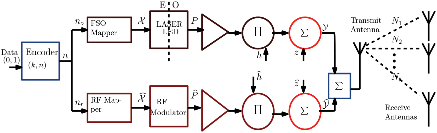
Figure 1: Block diagram of Free Space Communication System (FSCS)
In the FSCS system, FSO link is dynamic with instantaneous signal-to-noise ratio (SNR) on optical receiver
At the receiver, the optical received signal utilizing the IM/DD is modeled as Eq. (A.1) given in Appendix A. FSO Model. The model is dependent on the modulation process, in which the light radiation fluctuations are traversing a turbulent atmosphere, which is meant to include small and large scales effects correspondingly such as refraction and scattering. It characterizes the light irradiance, which is the product of two independent variables each with Gamma probability density function (PDF). The intensity
wherever
where
To express
By using [48], the cumulative density function (CDF) of
Considering the RF power
where
2.3 Diversity Combining Techniques
Diversity combining is suggested for mitigating the fading induced by the atmospheric turbulence. In the proposed system, SC and MRC diversity combining techniques are investigated and a comparison of each technique over the individual channel and the FSCS is developed to show the performance of each system under various conditions.
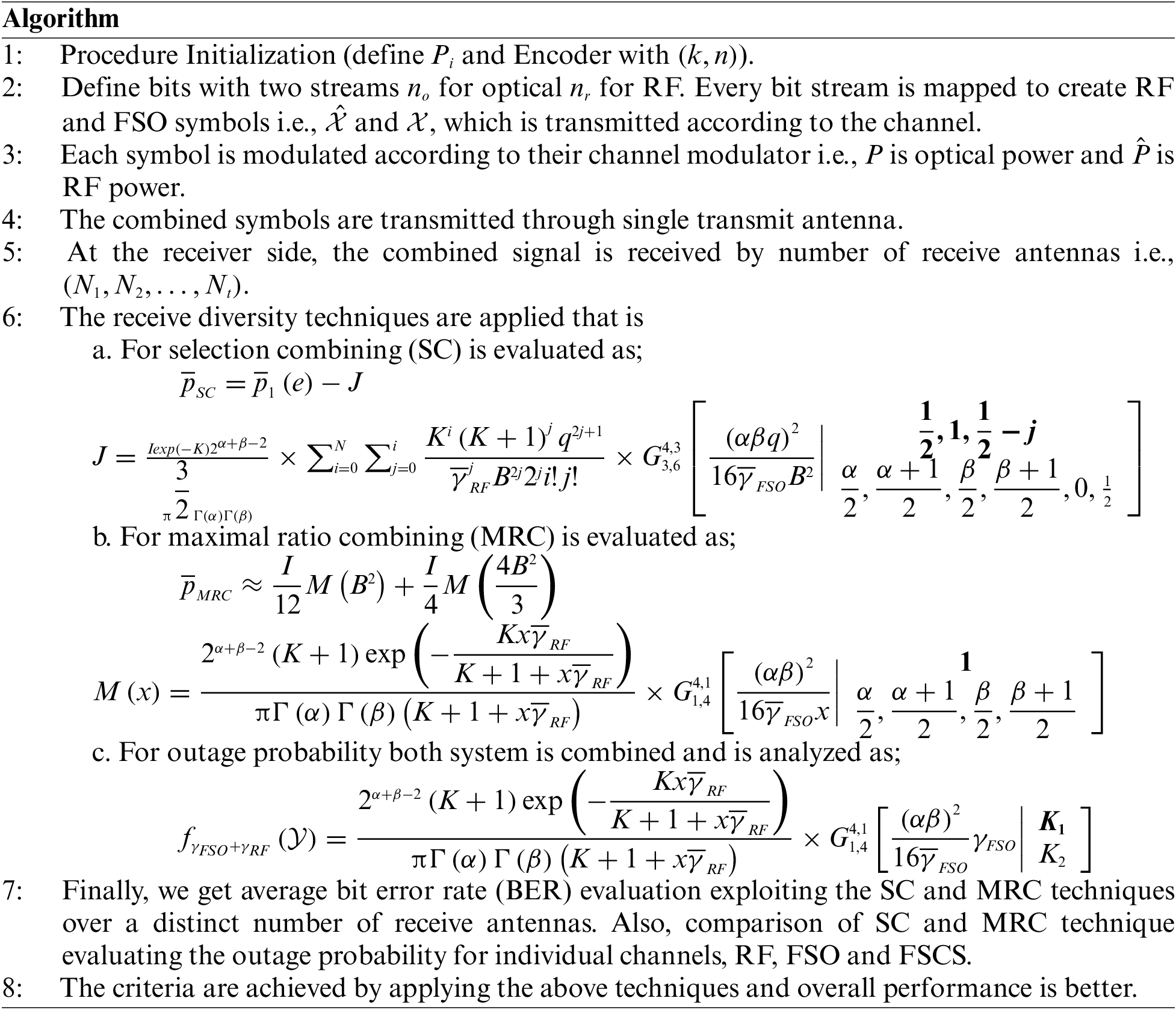
2.3.1 Selection Combining (SC)
SC is easy to deploy, in which a selection switch is employed and each branch is scanned overall SNR values. The receiving branch having the best instantaneous SNR is hooked up to the demodulator. The SNR output is calculated as Eq. (9);
The average BER of the SC can be obtained by Eq. (10);
where
The average BER of the receiver is approximated as Eq. (12);
wherever
2.3.2 Maximal Ratio Combining (MRC)
No doubt, SC is simple to compute but it requires continuous scanning, and is not always a finest diversity combining technique. In MRC scheme, the received signals of each branch can be combined, wherein the SNR of the output signal is the addition of the SNR of each branch with a weighting coefficient and is determined as Eq. (14),
Now at the moment, the output SNR will be gained by Eq. (15)
In MRC scheme, average BER overall performance is expressed as Eq. (16)
Q-function approximation [48] is used to evaluate Eq. (16). Accordingly, the average BER is obtained by Eq. (17)
where
At the receiver, the average BER performance can be obtained by Eq. (20)
Outage is defined by the property that the instantaneous output SNR
where
For the independent links, the
After substituting the values of
The combining techniques is employed over the proposed algorithm and error performance results are better.
The performance of the presented FSCS system and the individual channels (i.e., RF and FSO) is evaluated assuming SC and MRC combining techniques under strong turbulence channel conditions. For the simulation purpose, we use MATLAB. For the strong atmospheric turbulence, we assume
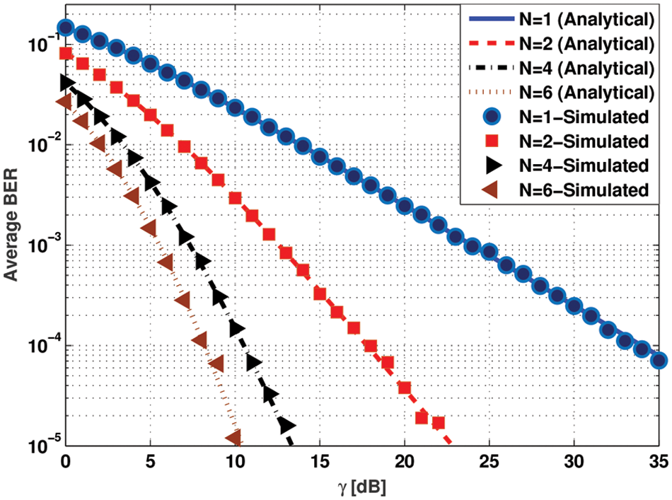
Figure 2: Average BER evaluation exploiting the SC technique over a distinct number of receive antennas
The MRC combining technique is evaluated and the simulation results of average BER are plotted exploiting the distinctive number of antennas in Fig. 3. It can be observed that the improvement of using 6 receiving antennas with respect to 2 receiving antenna is about
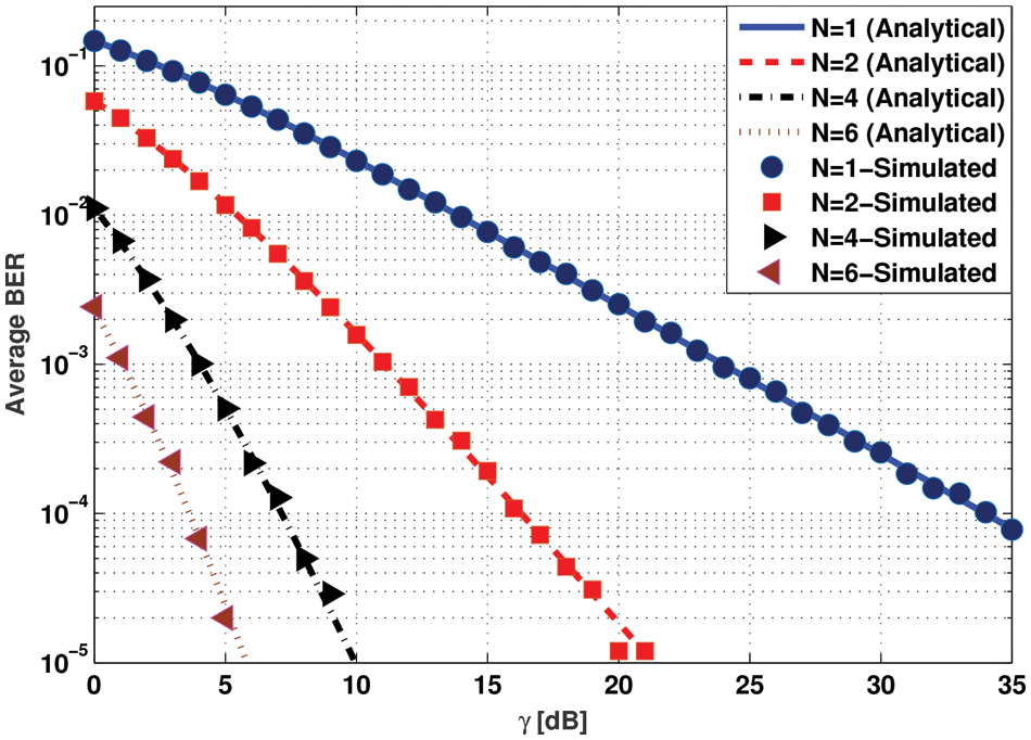
Figure 3: Evaluation of average BER exploiting the MRC technique using distinct number of receive antennas
In Fig. 4, the outage probability is evaluated employing both of the SC and MRC combining techniques and the results are compared for the individual channel (i.e., RF and FSO) as well as for the FSCS respectively. The simulation is performed for a fixed number of receive antenna (i.e.,
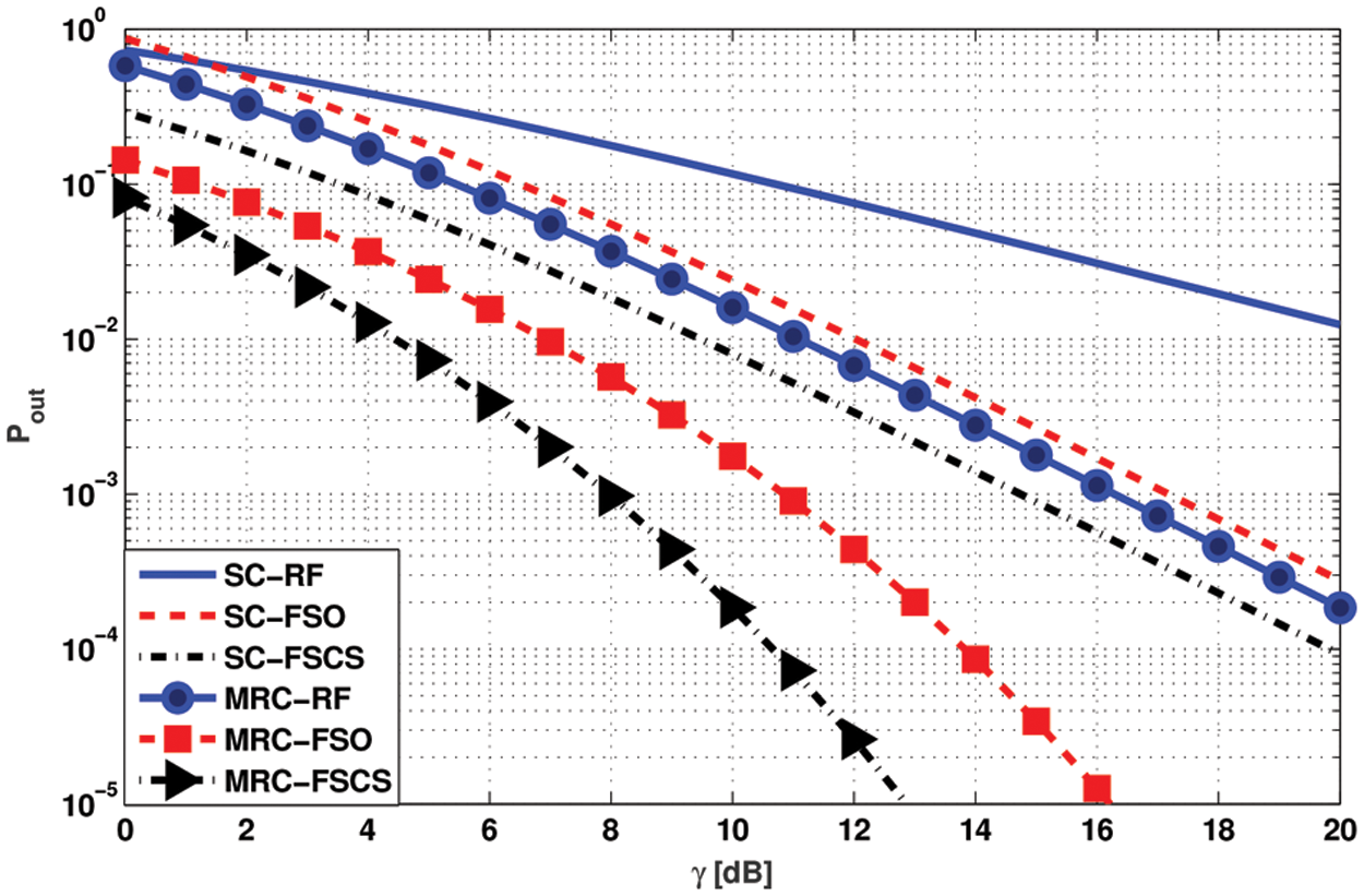
Figure 4: Comparison of SC and MRC technique evaluating the outage probability for individual channels (i.e., RF and FSO) and the FSCS, when N = 3
In Fig. 5, the outage probability of the FSCS employing the MRC technique is evaluated and the simulation results are plotted for a distinctive number of receive antennas. The SNR required to accomplish the aim of outage probability of
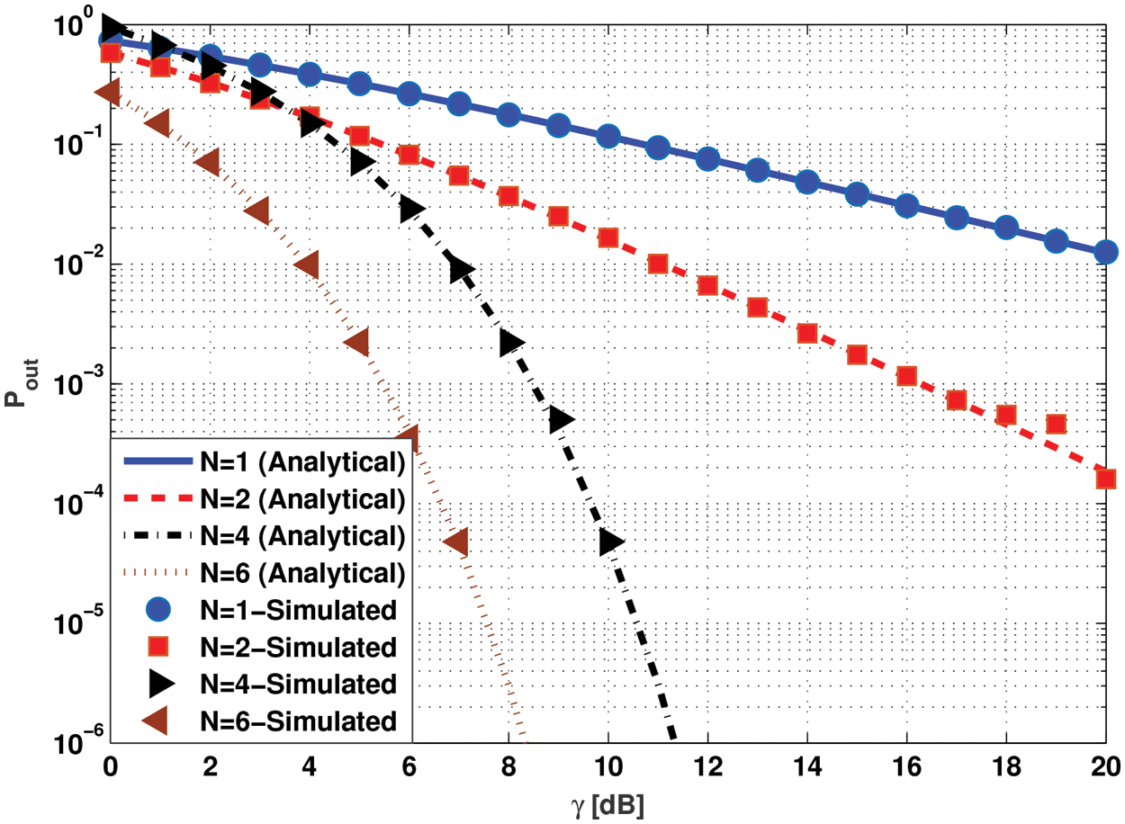
Figure 5: Evaluating the outage probability of the FSCS system exploiting different number of receive antennas and MRC combining technique
In this paper, we have compared the performance of FSO and RF systems with receive diversity compared with proposed FSCS. Outage probability of FSO and RF systems is compared with proposed FSCS in terms of SNR as shown in Fig. 6. At low outage probability of FSO is less than RF, which is almost equal with proposed FSCS with the increase of
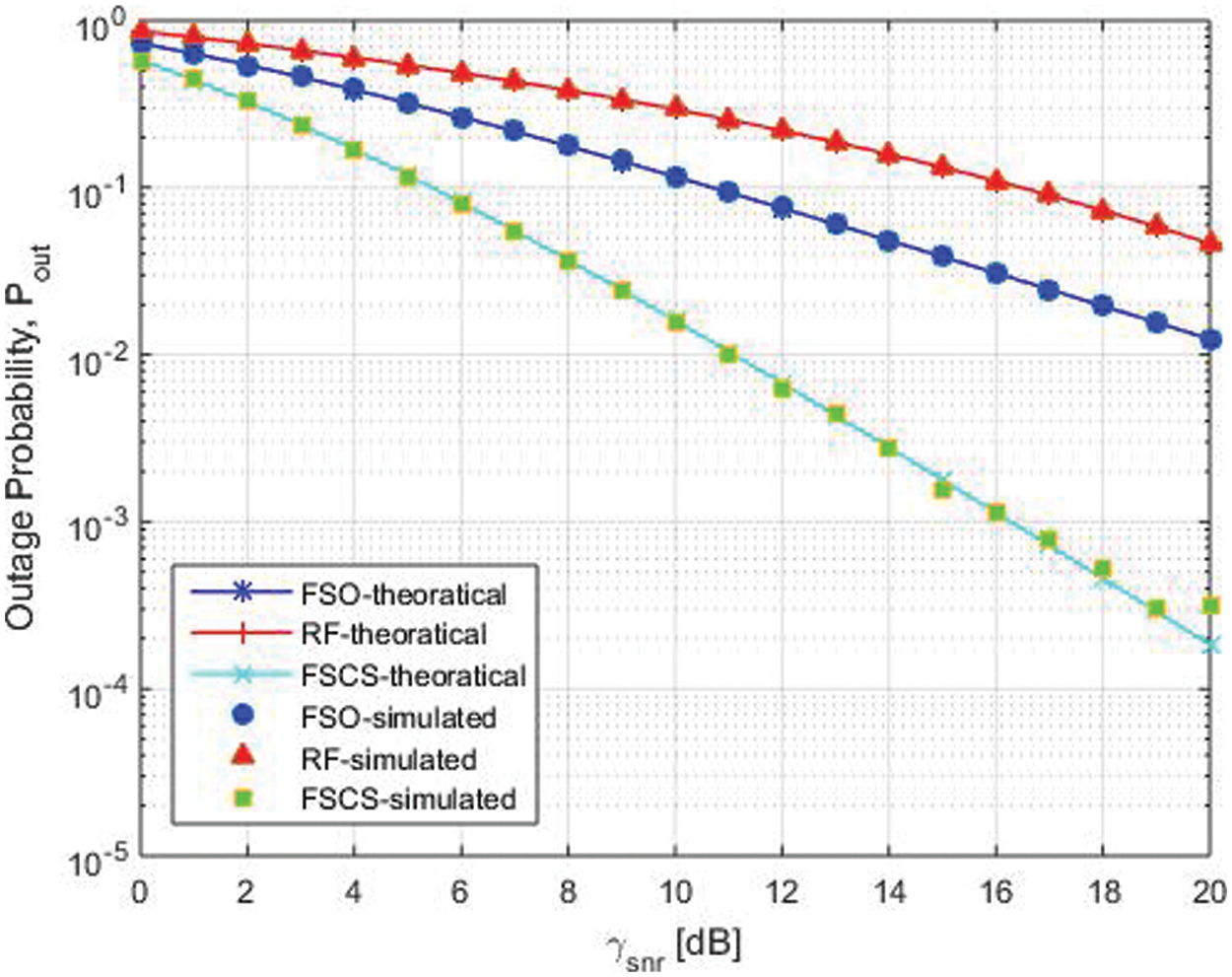
Figure 6: Comparison FSO, RF and FSCS
In this paper, the FSCS system is proposed and different combining techniques, i.e., SC and MRC are developed considering the receive diversity. The outage probability and the average BER metrics are evaluated. Closed form expressions for the outage probability and BER for both the SC and MRC are derived. Simulation is performed over a distinct number of receive antennas employing the FSO, RF and FSCS systems. The proposed system FSCS outperforms the individual FSO and RF communication systems under strong atmospheric turbulence in terms of power gains for a fixed number of antennas as is shown in simulation results. From the simulation results, it is seen that using MRC, FSCS system performs well as compared to SC and giving a power gain of
The system model developed in this paper can be further investigated. We also believe that the proposed research works on the adaptive FSCS, which provides the better initialization for future research in terms of adaptivity and flexibility. For example, we apply our system model on MIMO, which would be interesting to investigate as well as consider the RF channel as a Rician fading channel and see its effects on the system.
Acknowledgement: The authors would like to thank Dr. Tausif Zahid and Dr. Qasim Awais for their thorough discussion and helping in completing the research work.
Funding Statement: The authors received no specific funding for this study.
Conflicts of Interest: The authors declare that they have no conflicts of interest to report regarding the present study.
References
1. M. A. Khalighi and M. Uysal, “Survey on free space optical communication: A communication theory Perspective,” IEEE Communication Survey Tutorials, vol. 16, no. 4, pp. 2231–2258, 2014. [Google Scholar]
2. M. N. Khan, H. Kashif and A. Rafay, “Performance and optimization of hybrid FSO/RF communication system in varying weather,” Photonic Networking Communication, vol. 2020, no. 1, pp. 1–10, 2021. [Google Scholar]
3. T. Rakia, H. C. Yang, M. S. Alouini and F. Gebali, “Outage analysis of practical FSO/RF hybrid system with adaptive combining,” IEEE Communication Letters, vol. 19, no. 8, pp. 1366–1369, 2015. [Google Scholar]
4. Q. Fan, G. Zhou, T. Gui, C. Lu and A. Lau, “Advancing theoretical understanding and practical performance of signal processing for nonlinear optical communications through machine learning,” Nature Communication, vol. 11, no. 1, pp. 1–11, 2020. [Google Scholar]
5. A. Lobato, F. Ferreira, B. Inan, S. Adhikari, M. Kuschnerov et al., “Maximum-likelihood detection in few-mode fiber transmission with mode-dependent loss,” IEEE Photonics Technology Letter, vol. 25, no. 12, pp. 1095–1098, 2013. [Google Scholar]
6. J. Anguita, M. Neifeld and B. Vasic, “Turbulence-induced channel crosstalk in an orbital angular momentum-multiplexed free-space optical link,” Applied Optics, vol. 47, no. 13, pp. 2414–2429, 2008. [Google Scholar]
7. G. Xie, L. Li, Y. Ren, H. Huang, Y. Yan et al., “Performance metrics and design considerations for a free-space optical orbital-angular-momentum-multiplexed communication link,” Optica, vol. 2, no. 4, pp. 357–365, 2015. [Google Scholar]
8. K. Fontaine, R. Ryf, H. Chen, D. T. Neilson, K. Kim et al., “Longevity defined as top 10% survivors and beyond is transmitted as a quantitative genetic trait,” Nature Communications, vol. 10, no. 1, pp. 35, 2019. [Google Scholar]
9. H. Song, H. Song, R. Zhang, K. Manukyan, L. Li et al., “Experimental mitigation of atmospheric turbulence effect using pre-signal combining for uni- and bi-directional free-space optical links with two 100-Gbit/s OAM-multiplexed channels,” Journal of Lightwave Technology, vol. 38, no. 1, pp. 82–89, 2020. [Google Scholar]
10. P. Freire, J. Prilepsky, Y. Osadchuk, S. Turitsyn and V. Aref, “Neural networks based post-equalization in coherent optical systems: Regression versus classification,” arXiv preprint arXiv:2109.13843, vol. 2, pp. 1–9, 2021. [Google Scholar]
11. X. Liu, H. Lun, M. Fu, Y. Fan, L. Yi et al., “AI-based modeling and monitoring techniques for future intelligent elastic optical networks,” Applied Science, vol. 10, no. 1, pp. 363, 2020. [Google Scholar]
12. B. Yin, S. W. Zhou, S. W. Zhang, K. Gu and F. Yu, “On efficient processing of continuous reverse skyline queries in wireless sensor networks,” KSII Transactions on Internet and Information Systems, vol. 11, no. 4, pp. 1931–1953, 2017. [Google Scholar]
13. J. M. Zhang, K. Yang, L. Y. Xiang, Y. S. Luo, B. Xiong et al., “A self-adaptive regression-based multivariate data compression scheme with error bound in wireless sensor networks,” International Journal of Distributed Sensor Networks, vol. 9, no. 3, pp. 913497, 2013. [Google Scholar]
14. J. Wang, C. Ju, Y. Gao, A. K. Sangaiah and G. J. Kim, “A PSO based energy efficient coverage control algorithm for wireless sensor networks,” Computers Materials & Continua, vol. 56, no. 3, pp. 433–446, 2018. [Google Scholar]
15. J. Wang, X. J. Gu, W. Liu, A. K. Sangaiah and H. J. Kim, “An empower hamilton loop based data collection algorithm with mobile agent for WSNs,” Human-centric Computing and Information Sciences, vol. 9, no. 1, pp. 1–14, 2019. [Google Scholar]
16. J. Wang, Y. Gao, C. Zhou, S. Sherratt and L. Wang, “Optimal coverage multi-path scheduling scheme with multiple mobile sinks for WSNs,” Computers, Materials & Continua, vol. 62, no. 2, pp. 695–711, 2020. [Google Scholar]
17. J. Wang, Y. Gao, W. Liu, W. Wu and S. J. Lim, “An asynchronous clustering and mobile data gathering schema based on timer mechanism in wireless sensor networks,” Computers, Materials & Continua, vol. 58, no. 3, pp. 711–725, 2019. [Google Scholar]
18. J. Wang, Y. Gao, X. Yin, F. Li and H. J. Kim, “An enhanced PEGASIS algorithm with mobile sink support for wireless sensor networks,” Wireless Communications and Mobile Computing, vol. 2018, pp. 1–9, 2018. [Google Scholar]
19. Q. Tang, K. Yang, P. Li, J. M. Zhang, Y. S. Luo et al., “An energy efficient MCDS construction algorithm for wireless sensor networks,” EURASIP Journal on Wireless Communications and Networking, vol. 2012, no. 1, pp. 102, 2012. [Google Scholar]
20. Z. Liao, J. Wang, S. Zhang, J. Cao and G. Min, “Minimizing movement for target coverage and network connectivity in mobile sensor networks,” IEEE Transactions on Parallel and Distributed Systems, vol. 26, no. 7, pp. 1971–1983, 2014. [Google Scholar]
21. M. Portnoi, P. A. Haigh, T. J. Macdonald, F. Ambroz, I. P. Parkin et al., “Bandwidth limits of luminescent solar concentrators as detectors in free-space optical communication systems,” Light: Science & Applications, vol. 10, no. 1, pp. 1–12, 2021. [Google Scholar]
22. H. Huang, G. Xie, Y. Yan, N. Ahmed, Y. Ren et al., “100 Tbit/s free-space data link enabled by three-dimensional multiplexing of orbital angular momentum, polarization, and wavelength,” Optics Letters, vol. 39, no. 2, pp. 197–200, 2014. [Google Scholar]
23. A. Willner and C. Liu, “Perspective on using multiple orbital-angular-momentum beams for enhanced capacity in free-space optical communication links,” Nanophotonics, vol. 10, no. 1, pp. 225–233, 2021. [Google Scholar]
24. T. Xu, N. A. Shevchenko, Y. Zhang, C. Jin, J. Zhao et al., “Information rates in kerr nonlinearity limited optical fibre communication systems,” Optics Express, vol. 29, no. 11, pp. 17428–17439, 2021. [Google Scholar]
25. Z. Yang, W. Yu, G. Peng, Y. Liu and L. Zhang, “Recent progress on novel DSP techniques for mode division multiplexing systems: A Review,” Applied Science, vol. 11, no. 4, pp. 1363, 2021. [Google Scholar]
26. H. Kashif, M. N. Khan and A. Altalbe, “Hybrid optical-radio transmission system link quality: link budget analysis,” IEEE Access, vol. 8, pp. 65983–65992, 2020. [Google Scholar]
27. M. Uysal, J. Li and M. Yu, “Error rate performance analysis of coded free-space optical links over gamma-gamma atmospheric turbulence channels,” IEEE Transaction on Wireless Communication, vol. 5, no. 6, pp. 1229–1233, 2006. [Google Scholar]
28. X. Zhu, J. Kahn and J. Wang, “Mitigation of turbulence-induced scintillation noise in free-space optical links using temporal-domain detection techniques,” IEEE Photonics Technology Letters, vol. 15, no. 4, pp. 623–625, 2003. [Google Scholar]
29. S. Navidpour, M. Uysal and M. Kavehrad, “BER performance of free-space optical transmission with spatial diversity,” IEEE Transaction on Wireless Communication, vol. 6, no. 8, pp. 2813–2819, 2007. [Google Scholar]
30. E. J. Lee and V. Chan, “Diversity coherent receivers for optical communication over the clear turbulent atmosphere,” in IEEE Int. Conf. on Communications, Glasgow, UK, pp. 2485–2492, 2007. [Google Scholar]
31. E. J. Lee and V. Chan, “Diversity coherent and incoherent receivers for free-space optical communication in the presence and absence of interference,” Journal of Optical Communications and Networking, vol. 1, no. 5, pp. 463–483, 2009. [Google Scholar]
32. N. Letzepis and A. G. Fabregas, “Outage probability of the gaussian mimo free-space optical channel with PPM,” IEEE Transactions on Communications, vol. 57, no. 12, pp. 3682–3690, 2009. [Google Scholar]
33. F. Xu, M. A. Khalighi, P. Causse and S. Bourennane, “Channel coding and time-diversity for optical wireless links,” Optics Express, vol. 17, no. 2, pp. 872–887, 2009. [Google Scholar]
34. W. Popoola and Z. Ghassemlooy, “BPSK subcarrier intensity modulated free-space optical communications in atmospheric turbulence,” Journal of Lightwave technology, vol. 27, no. 8, pp. 967–973, 2009. [Google Scholar]
35. H. Manor and S. Arnon, “Performance of an optical wireless communication system as a function of wavelength,” Applied Optics, vol. 42, no. 21, pp. 4285–4290, 2003. [Google Scholar]
36. E. Lee and V. W. Chan, “Part 1: Optical communication over the clear turbulent atmospheric channel using diversity,” IEEE Journal on Selected Areas in Communications, vol. 22, no. 9, pp. 1896–1906, 2004. [Google Scholar]
37. M. A. Amirabadi, “New expression on the performance of a novel multi-hop relay-assisted hybrid FSO/RF communication system with receive diversity,” arXiv preprint arXiv:1806.02269, vol. 2, pp. 1–8, 2018. [Google Scholar]
38. H. Wang, L. Xu and X. Wang, “Outage probability performance prediction for mobile cooperative communication networks based on artificial neural network,” Sensors, vol. 19, no. 21, pp. 4789, 2019. [Google Scholar]
39. S. Ghoname, H. A. Fayed, A. A. Aziz and M. H. Aly, “Performance evaluation of an adaptive hybrid FSO/RF communication system: Impact of weather attenuation,” Iranian Journal of Science and Technology, Transactions of Electrical Engineering, vol. 44, no. 1, pp. 119–128, 2020. [Google Scholar]
40. N. Vishwakarma and S. Ramabadran, “Performance analysis of hybrid FSO/RF communication over generalized fading models,” Optics Communication, vol. 487, no. 4, pp. 126796, 2021. [Google Scholar]
41. H. Liang, Y. Li, M. Miao, C. Gao and X. Li, “Analysis of selection combining hybrid FSO/RF systems considering physical layer security and interference,” Optics Communication, vol. 497, no. 11, pp. 127146, 2021. [Google Scholar]
42. S. Song, Y. Liu, T. Xu, S. Liao and L. Guo, “Channel prediction for intelligent fso transmission system,” Optics Express, vol. 29, no. 17, pp. 27882–27899, 2021. [Google Scholar]
43. M. Amirabadi and V. Vakili, “A novel hybrid FSO/RF communication system with receive diversity,” Optik, vol. 184, no. June 6, pp. 293–298, 2018. [Google Scholar]
44. C. Wei and Z. Zhang, “Analysis of dual-hop AF relay systems in mixed RF and FSO links,” arXiv preprint arXiv:1711.09520, vol. 1, pp. 1–4, 2017. [Google Scholar]
45. M. Kafafy, Y. Fahmy, M. M. Khairy and M. Abdallah, “Secure backhauling over adaptive parallel mmwave/FSO link,” in IEEE Int. Conf. on Communications Workshops, Dublin, Ireland, pp. 1–6, 2020. [Google Scholar]
46. M. Amirabadi and V. Vakili, “On the performance of a novel multi-hop relay-assisted hybrid FSO/RF communication system with receive diversity,” Optik, vol. 226, no. 2, pp. 165883, 2021. [Google Scholar]
47. M. Siddharth, S. Shah, N. Vishwakarma and S. Ramabadran, “Performance analysis of adaptive combining based hybrid FSO/RF terrestrial communication,” IET Communication, vol. 14, no. 22, pp. 4057–4068, 2021. [Google Scholar]
48. M. Chiani, D. Dardari and M. K. Simon, “New exponential bounds and approximations for the computation of error probability in fading channels,” IEEE Transaction on Wireless Communication, vol. 2, no. 4, pp. 840–845, 2003. [Google Scholar]
49. M. K. Simon and M. S. Alouini, “Digital communications over fading channels,” IEEE Transactions on Information Theory, vol. 54, no. 7, pp. 3369–3370, 2005. [Google Scholar]
50. F. Zhang, T. Jing, Y. Huo and K. Jiang, “Outage probability minimization for energy harvesting cognitive radio sensor networks,” Sensors, vol. 17, no. 2, pp. 224, 2017. [Google Scholar]
51. I. Gradshteyn and I. Ryzhik, Table of integrals, series, and products. Academic Press, USA, 2014. [Google Scholar]
52. S. Bloom and S. Hartley, The last mile solution: Hybrid FSO radio. Whitepaper, AirFiber Inc, Seattle WA, USA, pp. 1–20, 2002. [Google Scholar]
53. B. He and R. Schober, “Bit-interleaved coded modulation for hybrid RF/FSO systems,” IEEE Transaction on Communication, vol. 57, no. 12, pp. 3753–3763, 2009. [Google Scholar]
Appendix A. FSO Model
Considering an optical power
where
where
where
where
Appendix B. RF Model
Consider the RF power
where
where
where
where
 | This work is licensed under a Creative Commons Attribution 4.0 International License, which permits unrestricted use, distribution, and reproduction in any medium, provided the original work is properly cited. |