| Computers, Materials & Continua DOI:10.32604/cmc.2022.031532 | |
| Article |
Asymmetric Patch Element Reflectarray with Dual Linear and Dual Circular Polarization
1Department of Electronic Engineering, Dawood University of Engineering and Technology, Karachi, Sindh, 74800, Pakistan
2Wireless Communication Centre, Universiti Teknologi Malaysia, 81301, Johor Bahru, Malaysia
3Centre for Telecommunication Research & Innovation (CETRI), Faculty of Electrical and Electronic Engineering Technology, Universiti Teknikal Malaysia Melaka (UTeM), Melaka, 76100, Malaysia
4Faculty of Electrical and Electronic Engineering, Universiti Tun Hussein Onn Malaysia, Batu Pahat, 86400, Johor, Malaysia
5Electrical Engineering Department, College of Engineering, Imam Mohammad Ibn Saud Islamic University, Riyadh, Saudi Arabia
*Corresponding Author: Z. A. Shamsan. Email: zashamsan@imamu.edu.sa
Received: 20 April 2022; Accepted: 12 June 2022
Abstract: A reflectarray antenna consisting of asymmetrical patch elements is proposed, which is capable of producing dual linear and dual circular polarized operation at 26 GHz frequency. The main purpose of this design is to support four different polarizations using the same patch element. The proposed reflectarray has a single layer configuration with a linearly polarized feed and circular ring slots in the ground plane. Asymmetric patch element is designed from a square patch element by tilting its one vertical side to some optimized inclination. A wide reflection phase range of 600° is obtained with the asymmetric patch element during unit cell measurements. A 332 element circular aperture reflectarray is designed with the proposed configuration and experimentally validated with a linearly polarized prime feed configuration. Two different orientations of mirror and non-mirror asymmetric patch elements on the surface of reflectarray are analyzed. Dual linear polarization is obtained with the mirror orientation of the asymmetric patch elements on the surface of reflectarray. Alternatively, asymmetric patch elements without mirror orientation are demonstrated to produce dual circular polarization with the same linearly polarized feed. A maximum measured gain of 24.4 dB and 26.1 dB is achieved for dual linear and dual circular polarization, respectively. Their respective measured efficiencies are 28% and 41.3%, which are supported by a maximum −3 dB gain bandwidth of 13.8% and 11.5%. The circular polarization operation of the reflectarray is also supported by a 6 dB axial ratio bandwidth of 9.2%. The proposed asymmetric patch reflectarray antenna with polarization diversity, wide bandwidth and high gain is suitable to be used in many high frequency applications of 5G communication.
Keywords: 5G; reflectarray; polarization diversity; circular polarization
An array of microstrip patches printed on a flat dielectric substrate and illuminated by an appropriately distant feed is known as a reflectarray antenna [1]. Its operating principle can be related to a parabolic reflector with a similar design architecture to a phased array antenna. However, the flat surface of the reflectarray with a simple power dividing mechanism for array elements differentiates it from a curvy parabolic reflector and a complicated designed phased array [2]. These features of the reflectarray antenna help in its smooth advancement to a higher frequency operation [3]. However, keeping a simple design architecture with advanced requirements for high frequency operation is a challenging task to acquire [4].
The performance of a reflectarray antenna depends on how well its reflected signals are collimated to form a parallel wavefront. High gain performance is guaranteed if the reflected signals are properly collimated off the reflected surface, which is usually complementary to a wide bandwidth performance [5]. These performance parameters of the reflectarray antenna are directly or indirectly related to the optimized design of its patch element. A wide phase range of the unit cell patch element ensures an enhanced bandwidth performance [4]. The effect of differential spatial phase delay, which is the main reason behind the narrow bandwidth of reflectarrays, is reduced when a wide reflection phase range is utilized for progressive phase distribution on the reflectarray surface [1,6]. The wide progressive phase span also eliminates the chances of phase error generation and helps in getting the proper collimation of reflected signals from a wide range of frequencies [7]. In general, both gain and bandwidth performance of reflectarray can be improved with a wide reflection phase range of its unit cell patch element.
Apart from its gain and bandwidth, the diversity in its polarization operation is also a crucial parameter to consider for its good performance. Polarization diversity is useful in acquiring a wider bandwidth by re-using the same frequency with different polarizations for high frequency applications [8]. A reflectarray antenna can be designed to offer dual linear polarization (LP) or dual circular polarization (CP) operation. Dual LP can be further categorized as vertical polarization (VL) and horizontal polarization (HP), whereas dual CP can be divided into right hand circular polarization (RHCP) and left hand circular polarization (LHCP). The physical shape of the unit cell patch element has much importance to either producing dual LP or dual CP reflected signals. Geometrically symmetric patch designs such as square and circular elements can easily support dual LP operation. On the other hand, a dual CP operation comes with much more design effort to produce reliable results [8]. Basic design specifications needed in dual LP and dual CP reflectarray operation are summarized in Tab. 1. Both dual LP and dual CP designs can offer single band or dual band frequency operation. Single band designs need single layer reflectarrays, whereas dual band designs can be produced with a single or dual layer reflectarrays. Dual band designs with a single layer contain two different patch elements supporting their respective band of frequency operation. Alternatively, two different layers support two different bands of frequency operation respectively. Dual LP reflectarrays need an LP feed, however, in some cases, two feeds are also used to produce simultaneous dual LP operation. Otherwise, two feeds are only selected in case, if dual band frequency operation is required. Dual CP reflectarray designs are normally produced with dual CP feed. An extra polarizer layer is also used sometimes in front of an LP reflectarray to convert CP signals into LP signals, and vice versa, coming from a dual CP feed. An LP feed can also be used to produce dual CP operation, but in this case, the reflectarray itself has to work as a polarization transform unit to convert incoming LP signals into reflected CP signals. These types of designs are the most complex and usually take a lot of design effort with dual or even multi-layer reflectarrays.

Dual LP operation can easily be obtained with some conventional types of elements like square loops, circular loops, and crossed dipoles. The chances of rising mutual coupling issues are higher if two or more elements are used in the same unit cell of reflectarray [8]. This effect can be reduced by selecting a single element, but with chances of relatively higher cross polarization and weaker dual polarization operation. Some common types of elements of CP used in the literature are split rings [9], rotated crossed dipoles [10], aperture coupled patches [11] and circular patches [12]. Mechanical angular rotation of the elements can also help to produce CP operation [13]. A polarization transform unit for CP operation with a linear feed can be comprised of a double layer T-shaped element [14] or a circular patch with two elliptical cross slots [15]. Dual LP and dual CP are used for many applications, including mobile communications, wearable applications and 5G communications [16–18].
In general, the dual polarized operation of the reflectarray antenna comes with increased design complexity [8]. Additionally, it is also a complex task to acquire dual LP and dual CP operation from the same type of reflectarray antenna. Therefore, in this work, an asymmetric patch reflectarray antenna is introduced to achieve dual LP and dual CP operation from the same patch element with low design complexity. The asymmetric design of the patch element is selected to get a wideband dual resonant response, its detailed parametric studies are already discussed in [19]. On the other hand, this work purely focuses on the dual LP and CP operation of the asymmetric patch element. Cross polarization generated due to asymmetry of the patch elements is suppressed by mirroring the element orientation in dual LP operation. On the other hand, a dual CP operation is achieved without mirroring the element orientation. This paper is organized as; Section 2 describes the development, results and analysis of the asymmetric patch element. Dual LP and dual CP operation of an asymmetric patch reflectarray antenna are experimentally discussed in Section 3 and Section 4, respectively. In the end, a comparative analysis of the proposed asymmetric patch reflectarray antenna with other related works is presented in Section 5.
2 Asymmetric Patch Unit Cell Element
The proposed asymmetric patch element has been constructed from a square patch element. A 0.254 mm thick Rogers Rt/D 5880 material is selected for this design that offers a dielectric constant of 2.2. The inter element spacing has been set as λ/2 (5.77 mm) at 26 GHz frequency which also defines the dimensions of the substrate. The process of development of an asymmetric patch element from a square patch element is illustrated in Fig. 1a. As depicted in Fig. 1a, a side of the square patch has been titled to form some inclined angle (θ). This inclination on one side is responsible to generate two different lengths (L1 and L2) in the same patch element. Consequently, two different resonances can be acquired with this single asymmetric patch element of two different lengths. As stated in [20], the resonance of a patch element is linked to the dimension of its electrical length.
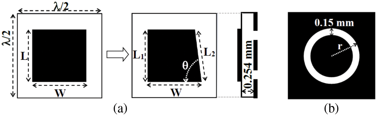
Figure 1: (a) Transformation of a square patch element into an asymmetric patch element (with full ground L1 = 3.59 mm, L2 = 3.61 mm, W = 3.77 mm, θ = 83.5°) (with ground ring slot L1 = 3.15 mm, L2 = 3.18 mm, W = 3.33 mm, θ = 82.6°) (b) Ground ring slot
The asymmetric patch element has been designed with a full ground and with a circular ring slot in the ground plane. To maintain the same resonance with different ground structures, the dimensions of the asymmetric patch element are modified accordingly. These optimized dimensions are indicated in the caption of Fig. 1. Fig. 1b shows the ground ring slot that is used to control the progressive phase distribution with a variable ring radius. This is because it is difficult to vary the overall size of the asymmetric patch element due to its design asymmetry. The ring slot in the ground plane could generate back radiations, which can be minimized by fixing the narrowest possible width of the ring slot. As depicted in Fig. 1b, a constant ring slot width of 0.15 mm is selected based on the available laboratory facilities for fabrication. Alternatively, only the slotted ring radius (r), with a fixed ring width, is varied to control the progressive phase range of the asymmetric unit cell element.
The optimized dimensions have been used to fabricate various samples of unit cell elements with variable ring radius, but the same patch size, as indicated in Fig. 2a. These fabricated unit cells are used for experimental verification. The unit cells are composed of two patch elements to spot any possibility of generating mutual coupling. Moreover, it makes a suitable dimension of the unit cell sample to properly fix it with the open face of the waveguide simulator [21]. As shown in Fig. 2b, a standard WR-34 adaptor is used to connect the waveguide simulator with the Vector Network Analyzer (VNA) for unit cell measurements. The waveguide simulator shares the same operating frequency range of 22 to 33 GHz with the WR-34 adaptor. However, the unit cell measurements are performed within the frequency range of 24 to 28 GHz.
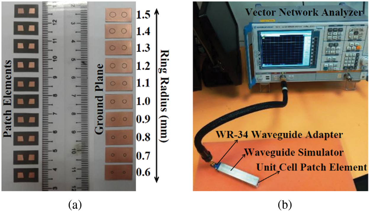
Figure 2: (a) Asymmetric patch unit cell elements with the variable radius of ground ring slots (b) measurement setup for unit cell elements
Measured and simulated reflection parameters of asymmetric patch unit cell element having full ground and slotted ground are plotted in Figs. 3a and 3b respectively. Fig. 3 confirms the attainment of dual resonance response of asymmetric patch element for both mentioned cases. However, a higher reflection loss is observed for the asymmetric patch element with the slotted ground as compared to the same element with the full ground. Leakage currents in the ground ring slot are responsible for this higher reflection loss. Moreover, higher measured losses are due to the connectors, cables and waveguide used during the measurements. Fig. 3 also shows that a measured linear reflection phase range of 480° is achieved with an asymmetric patch element of full ground. This value increased up to 510° when the ring slot is embedded in the ground plane. The wideband performance of the reflectarray antenna is linked with this wide reflection phase range.
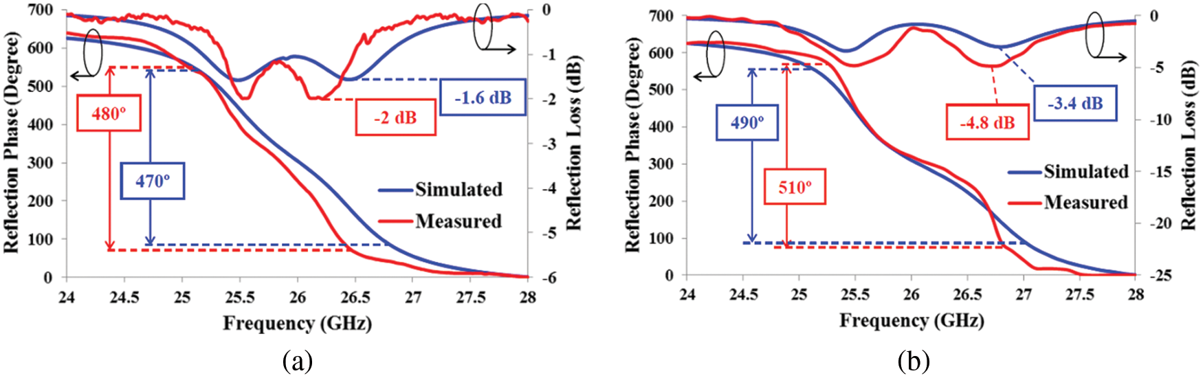
Figure 3: Reflection loss and reflection phase of the asymmetric patch element with (a) Full solid ground (b) Ground ring slot of r = 1 mm
Fig. 4 depicts the graphs of the progressive phase range of asymmetric patch element at 26 GHz frequency for both full ground and slotted ground cases. Fig. 4a shows that frequencies other than 26 GHz do not attain a smooth reflection phase curve when a full ground plane is used with an asymmetric patch element. A high design sensitivity of asymmetric patch element restricts it to offer a wideband performance. A full reflection phase span comes with a change of just 0.2 mm in length. This small change in size is practically difficult to achieve.
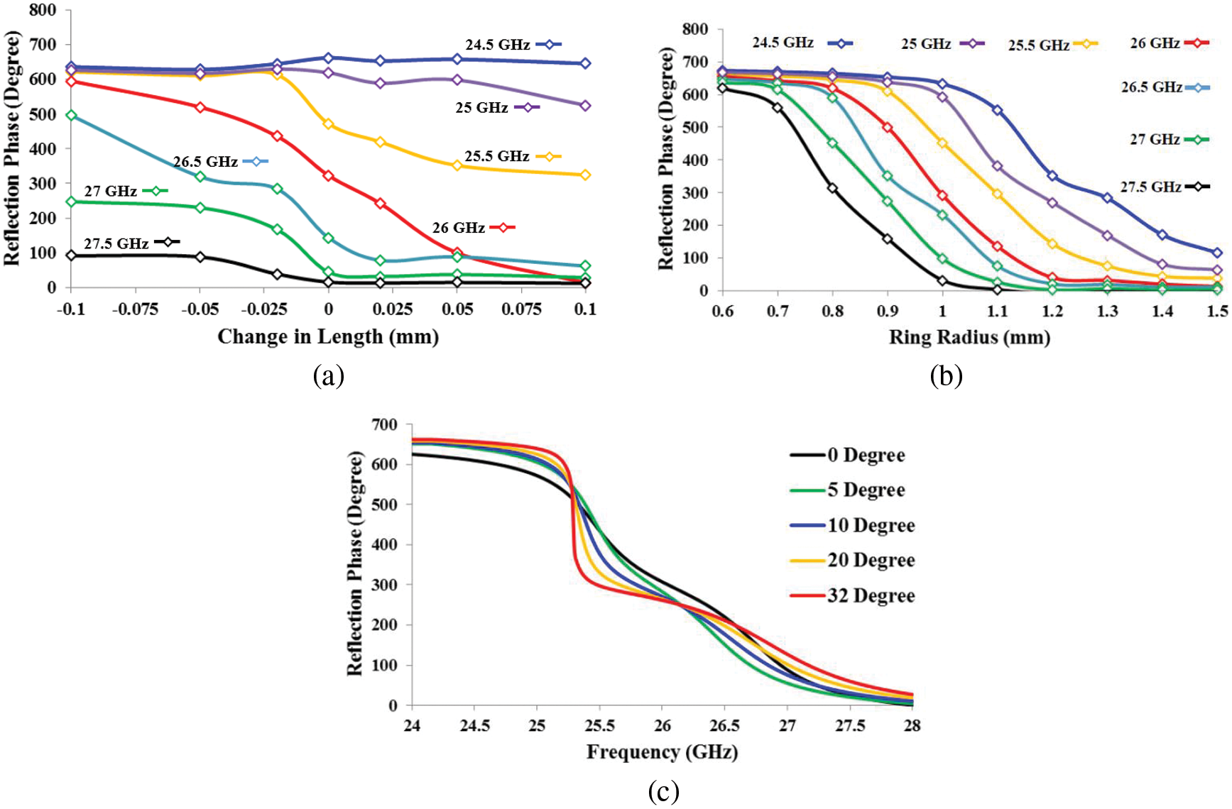
Figure 4: Reflection phase plots of asymmetric patch element (a) Measured with the full ground (b) Measured with ground ring slot (c) Simulated with the different incident angles at 26 GHz
On the other hand, an asymmetric patch element with a ground ring slot is comparably less design sensitive to offer a wide progressive phase range. It can be confirmed from Fig. 4b when a full reflection phase swing is attained with a 0.9 mm change in ring radius. A simulated reflection response of various incident angles to the surface of the asymmetric patch element with ground ring slot is shown in Fig. 4c. Fig. 4c illustrates that a wideband performance can be obtained with incident angles up to 32°. This value is carefully considered when the full reflectarray of asymmetric patch elements is designed.
3 Reflectarray Antenna with Dual Linear Polarization
The proposed asymmetric unit cell elements have been used to create a 332 element planar surface reflectarray. The full reflectarray is fed by a 10 dB horn antenna with an f/D of 0.8. Fig. 5 depicts the fabricated reflectarray antenna of different element orientations and the design of its ground plane. The progressive phase distribution over the surface of reflectarray is governed by the variable size of ground ring slots [1]. It allows keeping the same size of all the patch elements of reflectarray. Reflectarray with patch elements of mirror and non-mirror orientations have been shown in Figs. 5a and 5b, respectively. The reflection phase distribution over the surface of reflectarray to produce a plane wave is also depicted in Fig. 5b. The measurement setup of the reflectarray antenna in an anechoic chamber is shown in Fig. 5c. The reflectarray and its feed have been held up using a dielectric frame during the measurements. The dielectric frame poses negligible effects on the experimental outcomes.
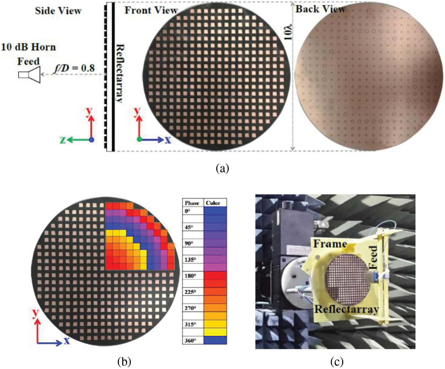
Figure 5: Reflectarray antenna of asymmetric patch elements (a) Elements with non-mirror orientation and ground ring slots (b) Elements with mirror orientation (c) Experimental setup
3.1 Radiation Parameters and Results of Dual Linear Polarization Operation
The mirror orientation of the asymmetric patch elements on the surface of the reflectarray is selected to suppress the cross polarization during its linear polarization operation [22]. The generation of the cross polarization in linearly polarized operation is otherwise inevitable due to the physically asymmetrical design of the patch elements. The asymmetric patch reflectarray is tested for a vertical polarization operation when the orientation of reflectarray is aligned with the direction of the incident electric field, as shown in Fig. 6a. To get the horizontal polarization results, the reflectarray orientation has been rotated 90° with the same original direction of the incident electric field, as depicted in Fig. 6b. Measured radiation pattern results of asymmetric patch reflectarray antenna with linear polarization have been compared with its simulated counterpart in Fig. 7.
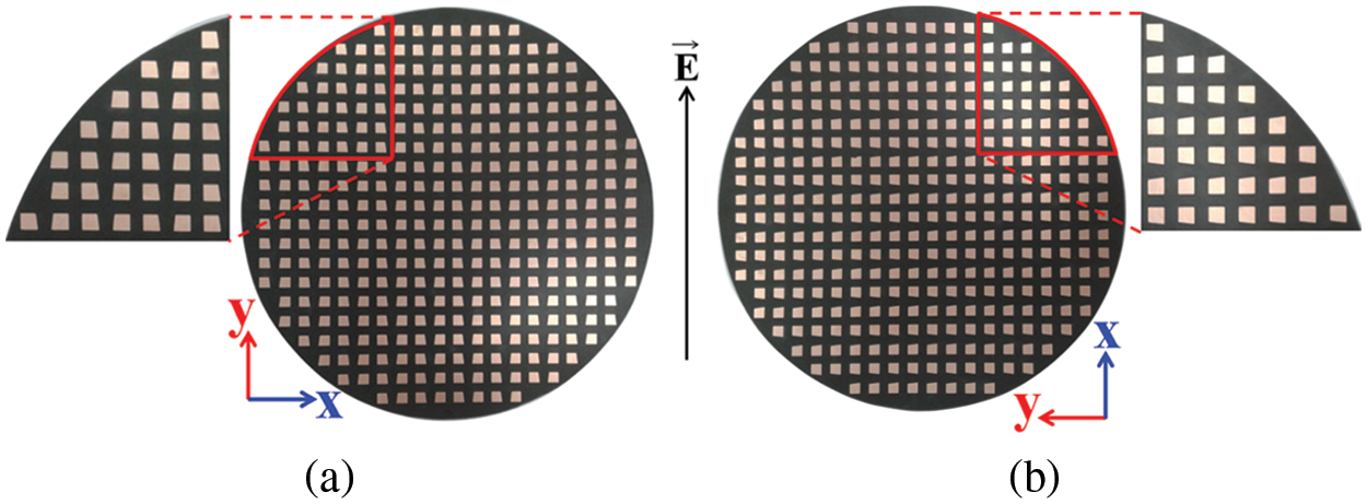
Figure 6: Different orientations of fabricated asymmetric patch reflectarray for dual linear polarization operation (a) for vertical polarization (b) for horizontal polarization
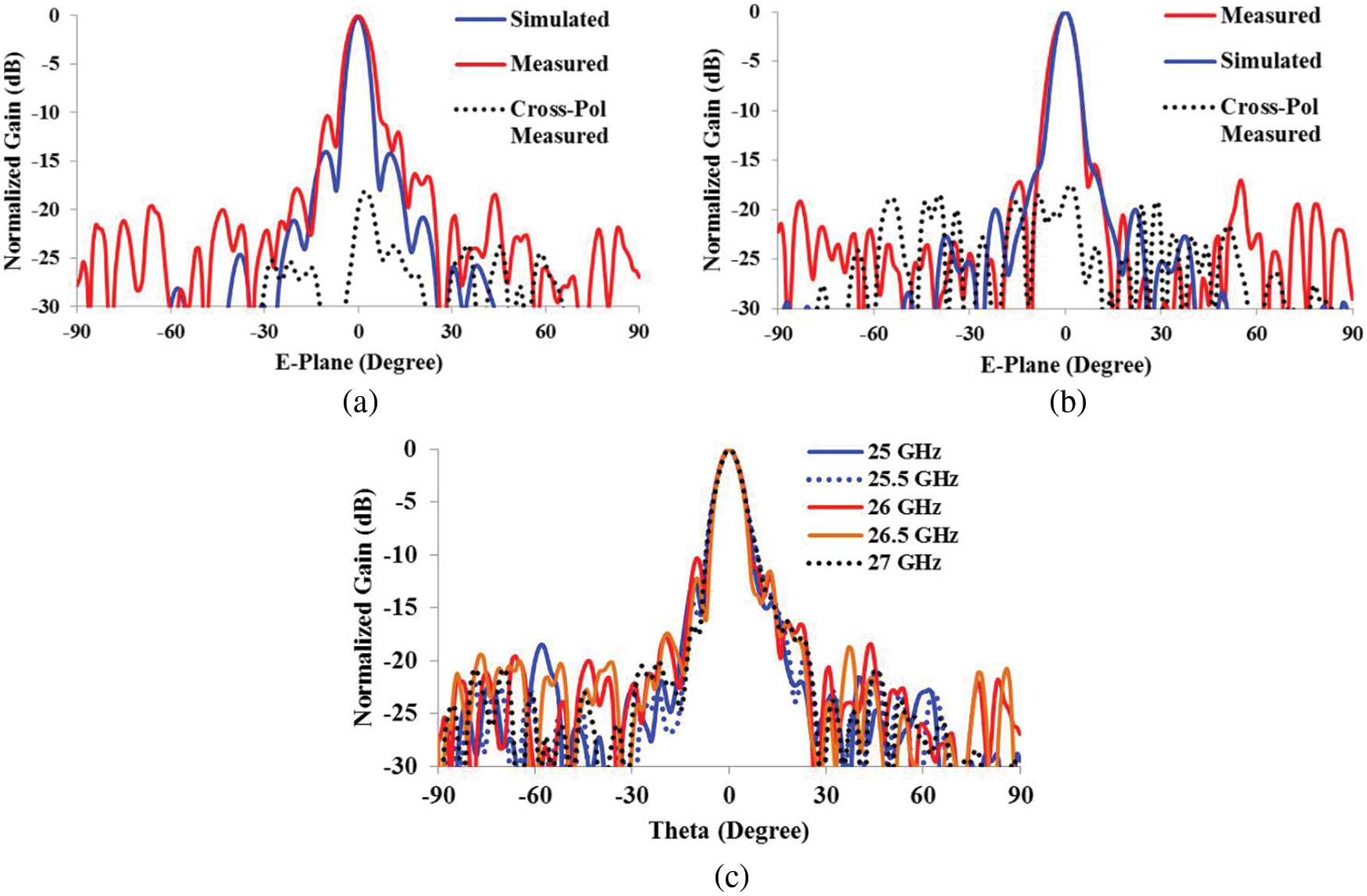
Figure 7: Radiation pattern plots of the reflectarray antenna of asymmetric patch elements with mirror orientation and embedded ground slots for (a) Vertical polarization at 26 GHz (b) Horizontal polarization at 26 GHz (c) Measured E-plane radiation curves at different frequencies
Plots of radiation patterns with vertical and horizontal polarization along with their respective cross polarizations are generated as shown in Figs. 7a and 7b, respectively. It is observed that the cross polarization is 19 and 20 dB below its co-pol counterparts in the broadside direction in Figs. 7a and 7b, respectively. Simulated cross polarization is omitted here for graph clarity. The overall trend of the simulated and measured radiation patterns is identical with minor discrepancies. Various radiation patterns are plotted at different frequencies in Fig. 7c, to validate the reliability of linear polarized results. These results have been obtained using a vertically polarized incident electric field on the surface of the reflectarray antenna with the mirror orientation of patch elements. The gain of the proposed reflectarray antenna with dual linear polarization is plotted against frequency in Fig. 8. Vertical polarization acquires a maximum measured gain of 24.4 dB that produces an aperture efficiency of 28%. A measured −3 dB gain bandwidth of 3 GHz is also attained which is equivalent to 11.5% at 26 GHz. The gain value has been observed to reduce slightly when the polarization of the reflectarray is changed from vertical to horizontal. This reduction is 0.5 dB, which forces horizontal polarization to achieve a measured gain of 23.9 dB with 25% aperture efficiency. However, the reduction in the gain produces a wider −3 dB gain bandwidth of 3.6 GHz, which is 13.8% of 26 GHz. Additionally, this gain reduction is also associated with a reduced measured side lobe level (SLL) as noticed in Fig. 7b.

Figure 8: Gain vs. frequency response of asymmetric patch reflectarray antenna with (a) Vertical polarization (b) Horizontal polarization
3.2 Comparison of Vertically and Horizontally Polarized Asymmetric Patch Reflectarray Antenna
It is necessary to compare the performance of asymmetric patch reflectarray antenna when it operates in both vertical and horizontal polarization. The main reason for this comparison is to see the difference between the results of two different linear polarizations of asymmetric patch reflectarray.
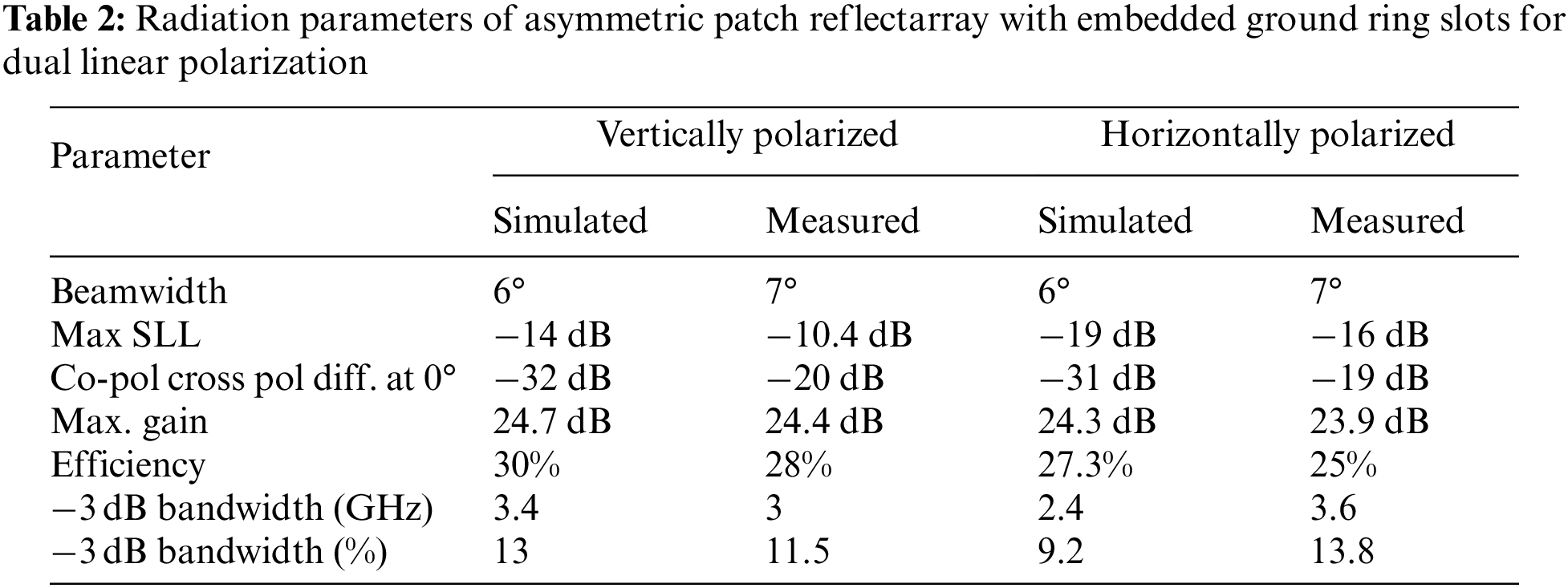
Simulated and measured results of asymmetric patch reflectarray with dual linear polarization are listed in Tab. 2. It can be observed that there is not much difference between the measured quantities of beamwidth, SLL and cross polarization of both polarizations. Instead, SLL is improved from −10.4 to −16 dB. On the other hand, a reduction of 0.5 dB in the measured maximum gain performance has been noticed, which also reduces the efficiency by 3%. The gain is slightly reduced because the reflectarray is initially designed for vertical polarization operation. Therefore, a horizontal polarization operation of the same reflectarray would result in a marginally lower gain performance. Alternatively, the measured bandwidth has been noticed to improve from 11.5% to 13.8%, which is mainly because of a slight reduction in the gain performance.
4 Reflectarray Antenna with Dual Circular Polarization
The primary purpose of designing asymmetric patch reflectarray is to attain a wider bandwidth performance. However, the high cross-polarization associated with the asymmetric patch reflectarray, when its elements are not in mirror orientation, is a major drawback. The high cross polarization performance of asymmetric patch reflectarray can be utilized progressively if it is considered to offer a circular polarization operation. Co-polarization and cross polarization components of the reflected electric field can be taken as the major and minor axis of the circular polarization respectively.
4.1 Right Hand Circular Polarization (RHCP)
The asymmetric design of the patch element generates two orthogonal components of reflected electric fields (Er), which can be represented as a major and minor axis for circular polarization operation. As shown in Fig. 9, the major axis that is directed from the lower right corner to the upper left corner of the asymmetric patch is slightly longer than the minor axis, which is pointed in an orthogonal direction. The major axis is the one that decides the type of circular polarization. It can be seen that the major axis is tilted from right to left direction and that is why it generates RHCP in a counter-clockwise direction as depicted in Fig. 9. Additionally, this RHCP operation can only be achieved if the incident electric field and asymmetric patch reflectarray are aligned vertically to each other.
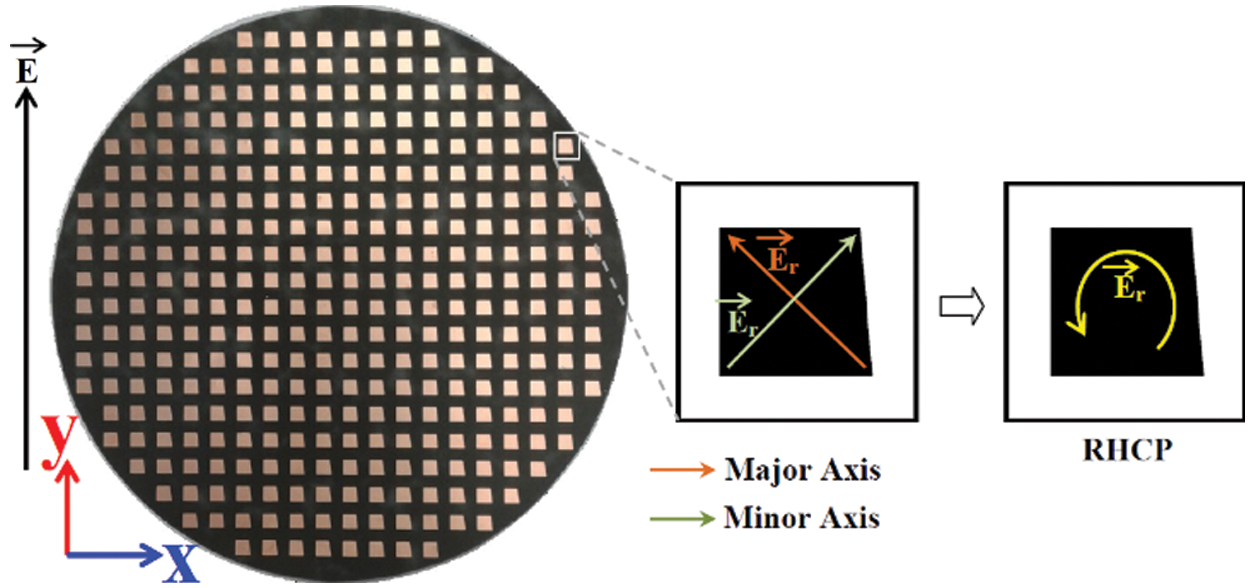
Figure 9: Asymmetric patch reflectarray with vertical orientation to attain RHCP
Asymmetric patch reflectarray with described settings has been measured for its circular polarization operation. Its simulated and measured radiation graphs are plotted in Fig. 10. It can be observed that a low cross polarization level of the asymmetric patch reflectarray has been obtained by testing it for circular polarization. It is because the co-polarization has appeared as RHCP and that is why LHCP serves as cross polarization. A decent agreement has been found between the measured and simulated co-polarized graph of the vertical cut of the radiation pattern, as shown in Fig. 10a. The measured cross polarization has also been plotted here, along with the co-polarized graph. A quite low level of cross polarization has been observed in the broadside direction, which is a sign of good performance of asymmetric patch reflectarray antenna with circular polarization operation.
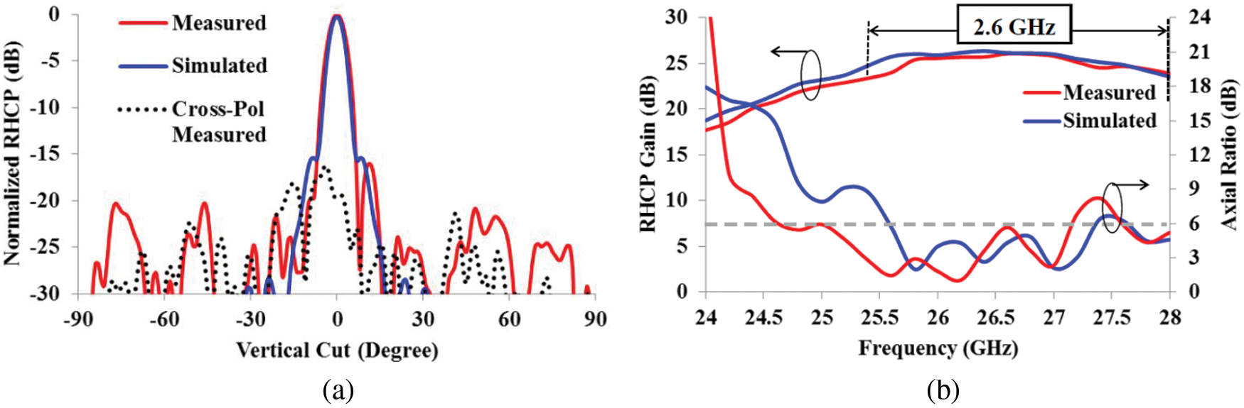
Figure 10: RHCP response of asymmetric patch reflectarray (a) Radiation pattern at 26 GHz (b) Gain and AR vs. frequency
The RHCP gain and axial ratio (AR) have also been measured and compared with the simulated results, as depicted in Fig. 10b. The measured gain shows very good reliability with the simulated gain. A low value of the AR is essential to get circular polarization. The benchmark could be drawn at 6 or 3 dB level, depending on the application, to see how much frequency band is operating under circular polarization. Fig. 10b shows that some portions of simulated and measured axial ratio curves are below the 3 dB level, but a 6 dB level is selected here to perform a fair and clear comparison between them [23]. The tabulated numerical values of simulated and measured radiation parameters of asymmetric patch reflectarray with RHCP operation are presented in Tab. 3. A good comparison can be observed between the simulated and measured quantities. As described earlier, the SLL is even better in measurements than the simulations. The maximum gain has been measured as just 0.3 dB less than the maximum simulated gain and it holds a total efficiency of 41.3%. Simulated and measured −3 dB bandwidths are also comparable with values of 11.5% and 10%, respectively. The AR bandwidth is taken at the 6 dB level of the axial ratio curve plotted in Fig. 10b. The measured AR bandwidth is observed to be 9.2%, which is slightly wider than its simulated counterpart, which is 7%. The better measured results are because of the slight shift in the resonant frequency of the reflectarray due to the fabrication tolerance.

4.2 Left Hand Circular Polarization (LHCP)
The asymmetric patch reflectarray without mirror orientation of its elements which has circular ring slots in the ground plane is now rotated 90° to hold a horizontal position with a vertically aligned incident electric field, as shown in Fig. 11. This horizontal orientation of the reflectarray also changes the interaction between the incident electric field and the asymmetric patch element. The major axis of the reflected electric field is now generated from the lower left corner to the upper right corner of the asymmetric patch element. It makes the major axis tilt from the left to the right direction and generates LHCP in the reflected electric field. As shown in Fig. 11, LHCP makes the reflected electric field rotate in a clockwise direction. It shows that the LHCP can be obtained by asymmetric patch reflectarray if it is held in a horizontal position with the vertically aligned electric field. The simulated and measured radiation pattern results of asymmetric patch reflectarray for LHCP are given in Fig. 12. It can be seen from Fig. 12a that the trend of LHCP results is somehow similar to the previously obtained RHCP results. The difference between them is the opposite direction of circular polarization for their co-polar and cross-polar components.
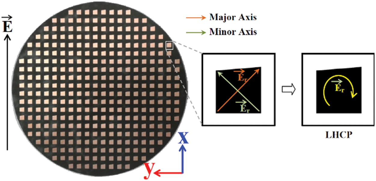
Figure 11: Asymmetric patch reflectarray with horizontal orientation to attain LHCP
It shows good stability in the reflectarray operation, even though its orientation has been changed from vertical to horizontal. It can be observed from Fig. 12a that the co-polar components of radiation patterns are plotted in LHCP, whereas RHCP is considered the cross-polar component. The simulated and measured graphs are well matched with each other. The gain has also been measured and compared with its simulated counterpart, as depicted in Fig. 12b. A good similarity has been found between the simulated and measured gain curves. The measured and simulated axial ratio, as plotted in Fig. 12b, also holds a low level to prove the LHCP operation of asymmetric patch reflectarray. The simulated and measured radiation pattern parameters of asymmetric patch reflectarray with LHCP operation are also compared in Tab. 3. A good match between the simulated and measured results can also be noticed in Tab. 3. The difference between measured and simulated gain has been just 0.4 dB, which brings an almost 4% difference in efficiency. Both types of bandwidths are also almost the same, except for a slight difference of 0.7% in simulated and measured AR bandwidth.
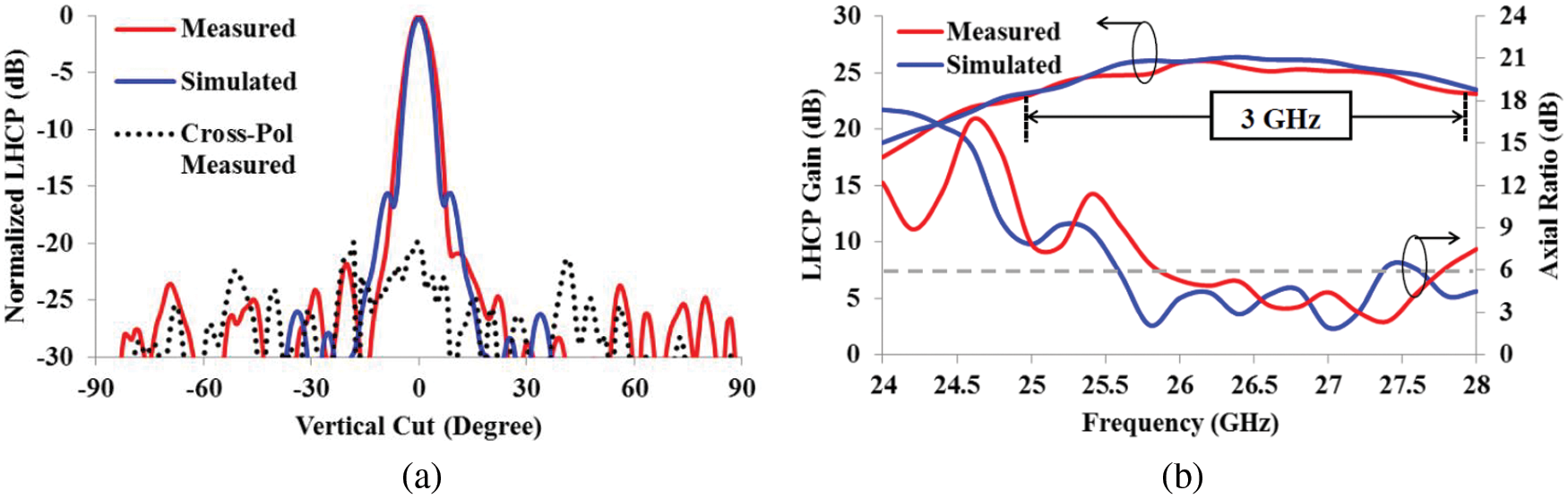
Figure 12: LHCP response of asymmetric patch reflectarray (a) Radiation pattern at 26 GHz (b) Gain and AR vs. frequency
4.3 Comparison Between RHCP and LHCP Response of the Asymmetric Patch Reflectarray Antenna
This analysis shows that dual circular polarization operation can be obtained by an asymmetric patch reflectarray with its two different angular orientations. The measured response of asymmetric patch reflectarray with RHCP and LHCP operation is almost similar to each other, as summarized in Tab. 3. The horizontal cuts of RHCP and LHCP radiation patterns have been plotted in Fig. 13 to show the reliability of the results in the orthogonal plane. The maximum measured gain only drops by 0.1 dB, when the reflectarray is used for LHCP instead of RHCP. Therefore, the measured efficiency of both circular polarization is also observed to be almost similar. It should be noted here that, the asymmetric patch reflectarray is comprised of circular ring slots in the ground plane. Circular ring slots, due to their angular symmetry, do not affect the circular polarization generated by the asymmetric patch element. The measured bandwidth of both circular polarizations is also comparable with a slight difference of 1.5% in −3 dB bandwidth. This percent difference is also the same for the AR bandwidth of both circular polarization, which is taken at a 6 dB level [24]. Moreover, the asymmetric patch reflectarray acts as a polarization transform unit, which converts linear polarization of the feed into reflecting circular polarization.

Figure 13: Measured horizontal cuts of radiation patterns of RHCP and LHCP at 26 GHz
5 Comparison with Other Related Works
The main contribution of this proposed work is to produce a reflectarray element that could support dual linear and dual circular polarization operation with the least possible design complexity. The design complexity increases with the addition of layers or by using an extra polarizer surface, especially in dual circular polarized designs. A fair comparison of this proposed work is made with other related works in Tab. 4. A design reported in [25] converts CP signals to LP and then LP signals back to CP using a polarizer layer in front of an LP reflectarray. This requires a dual CP feed and a lot of design efforts, which increases its design complexity. The inclusion of the air gap in the substrate is normally considered for bandwidth improvement. A stacked layered element reported in [26] utilizes 3 layers to reflect the incoming dual CP signals simultaneously. The design complexity restricts this design to working at lower frequencies with two different feeds for dual CP operation. Two pairs of three coplanar dipoles, reported in [27], were used for dual CP operation with a tactic of angular rotation. A dual CP feed is needed for that purpose, which can generate the required signal to reflect from the reflectarray. Three layers used in this design increase its design complexity due to the shorter wavelengths of 19.7 GHz frequency. All dual LP designs, as reported in [28–30], work to offer dual band operations at different frequencies. They possess low to moderate design complexity due to their single or just two layers of design configurations. On the other hand, they all require two different feeds for each selected band of frequency operation.

Regardless of a selected design, the gain of a reflectarray can be improved by a large electrical aperture and its bandwidth can be increased using multiple stacked layers (including an air gap). The improvement of gain and bandwidth are not under the scope of this proposed work that relies only on low design complexity for the generation of four different polarizations from the same patch element with a linearly polarized incident field. In comparison to all these reported works, this proposed design has a lower design complexity with a single patch, single layer and single linearly polarized feed to offer dual LP and dual CP operation.
A new asymmetric patch element has been proposed to create four different types of polarization with a linearly polarized center feed configuration. Asymmetry in the design of the reflectarray patch element is used to create the dual resonant response at 26 GHz frequency for a total phase span of more than 600°. Circular ring slots with variable radius are embedded in the ground plane of the reflectarray of 332 same sized asymmetric patch elements to smoothly attain the progressive phase distribution for a good gain and bandwidth performance. Cross polarization generated due to the asymmetric patch design is suppressed by mirroring the orientation of the elements on the reflectarray surface. This mirror configuration of the asymmetric patch elements supports dual linear polarization with a maximum gain and −3 dB bandwidth of 24.4 dB and 13.8%, respectively. On the other hand, without mirror orientation of the asymmetric patch elements on the surface of reflectarray produces a dual circular polarization with the same linearly polarized feed. A maximum gain, in this case, is 26.1 dB, which offers a maximum −3 dB bandwidth of 11.5%. A maximum value of measured cross polarization of around −20 dB is achieved for all four polarizations at their respective broadside directions. This limitation of slightly high cross polarization is due to the selection of a single layered patch element for dual polarization operation at a single frequency. However, this value of cross polarization is still quite low to affect the operation of its respective co-polar reflection. The usefulness of low design complexity with polarization diversity, as in this design, can be easily utilized for high frequency operation, which is a need of time.
Funding Statement: The authors extend their appreciation to the Deanship of Scientific Research at Imam Mohammad Ibn Saud Islamic University for funding this work through Research Group No. RG-21-12-08. The initials of the authors who receive the grant are: ZAS. The URL of the sponsor’s website: https://units.imamu.edu.sa/deanships/sr/Pages/default.aspx.
Conflicts of Interest: The authors declare that they have no conflicts of interest to report regarding the present study.
References
1. J. Huang and J. Encinar, Reflectarray Antennas, USA: Wiley Inter Science, 2007. [Google Scholar]
2. J. Huang, “Analysis of microstrip reflectarray antenna for microspacecraft applications,” Telecommun. Data Acquis. Prog. Rep., vol. TDA PR 42-, no. Spacecraft Telecommunications Equipment Section, pp. 153–173, 1994. [Google Scholar]
3. D. M. Pozar, D. Targoski, S. D. Targonski and H. D. Syrigos, “Design of millimeter wave microstrip reflectarrays,” IEEE Transactions on Antenna and Propagation, vol. 45, no. 2, pp. 287–296, 1997. [Google Scholar]
4. M. H. Dahri, M. H. Jamaluddin, M. Inam and M. R. Kamarudin, “A review of wideband reflectarray antennas for 5G communication systems,” IEEE Access, vol. 5, pp. 17803–17815, 2017. [Google Scholar]
5. D. M. Pozar, “Bandwidth of reflectarrays,” Electronic Letters, vol. 39, no. 21, pp. 1490–1491, 2003. [Google Scholar]
6. M. H. Dahri, M. Inam, M. H. Jamaluddin and M. R. Kamarudin, “A review of high gain and high efficiency reflectarrays for 5G communications,” IEEE Access, vol. 6, pp. 5973–5985, 2017. [Google Scholar]
7. M. H. Jamaluddin, R. Gillard, R. Sauleau and M. -A. Milon, “Perturbation technique to analyze mutual coupling in reflectarrays,” IEEE Antennas and Wireless Propagation Letters, vol. 8, pp. 697–700, 2009. [Google Scholar]
8. M. Hashim Dahri, M. H. Jamaluddin, M. Khalily, M. I. Abbasi, R. Selvaraju et al., “Polarization diversity and adaptive beamsteering for 5G reflectarrays: A review,” IEEE Access, vol. 6, pp. 19451–19464, 2018. [Google Scholar]
9. X. -J. Zhong, L. Chen, Y. Shi and X. -W. Shi, “Single-layer broadband circularly polarized reflectarray with subwavelength double-ring elements,” Electromagnetics, vol. 35, no. 4, pp. 217–226, 2015. [Google Scholar]
10. X. J. Zhong, L. Chen, Y. Shi and X. -W. Shi, “A dual-frequency single layer circularly polarized reflectarray with frequency selective surface backing,” Progress in Electromagnetic Research C, vol. 51, pp. 87–93, 2014. [Google Scholar]
11. M. Albooyeh, N. Komjani and M. S. Mahani, “A circularly polarized element for reflectarray antennas,” IEEE Antennas and Wireless Propagation Letters, vol. 8, pp. 319–322, 2009. [Google Scholar]
12. R. S. Malfajani and Z. Atlasbaf, “Design and implementation of a broadband single layer circularly polarized reflectarray antenna,” IEEE Antennas and Wireless Propagation Letters, vol. 11, pp. 973–976, 2012. [Google Scholar]
13. L. Martinez-Lopez, J. Rodriguez-Cuevas, A. E. Martynyuk and J. I. Martinez-Lopez, “Wideband-reconfigurable reflectarrays based on rotating loaded split rings,” Journal of Electromagnetic Waves and Applications, vol. 29, no. 2, pp. 218–232, 2016. [Google Scholar]
14. L. S. Ren, Y. C. Jiao, F. Li, J. J. Zhao and G. Zhao, “A dual-layer T-shaped element for broadband circularly polarized reflectarray with linearly polarized feed,” IEEE Antennas and Wireless Propagation Letters, vol. 10, pp. 407–410, 2011. [Google Scholar]
15. F. Ahmadi, A. Namiranian and B. Virdee, “Design and implementation of a single layer circularly polarized reflectarray antenna with linearly polarized feed,” Electromagnetics, vol. 35, no. 2, pp. 93–100, 2015. [Google Scholar]
16. S. Costanzo, S. Member, F. Venneri, A. Borgia, G. D. I. Massa et al., “Dual-band dual-linear polarization reflectarray for mm waves/5G applications,” IEEE Access, vol. 8, no. April, pp. 78183–78192, 2020. [Google Scholar]
17. K. N. Paracha, S. Kamal, A. Rahim, P. J. Soh and M. Khalily, “Wearable antennas: A review of materials, structures, and innovative features for autonomous communication and sensing,” IEEE Access, vol. 7, pp. 56694–56712, 2019. [Google Scholar]
18. M. Inam, M. H. Dahri, M. H. Jamaluddin, N. Seman, M. R. Kamarudin et al., “Design and characterization of millimeter wave planar reflectarray antenna for 5G communication systems,” International Jornal of RF and Microwave Computer-Aided Engineering, vol. 29, no. 9, pp. e21804, 2019. [Google Scholar]
19. M. H. Dahri, M. H. Jamaluddin, F. C. Seman, M. Inam, A. Y. I. Ashyap et al., “A novel asymmetric patch reflectarray antenna with ground ring slots for 5G communication systems,” Electronics, vol. 9, pp. 1450, 2020. [Google Scholar]
20. C. A. Balanis, “Antenna; Theory Analysis and Design,” 3rd. edition, John Wiley and sons, Hoboken-New Jersey, 2005. [Google Scholar]
21. M. I. Abbasi and M. Y. Ismail, “Reflection loss and bandwidth performance of X-band infinite reflectarrays: Simulations and measurements,” Microwave and Optical Technology Letters, vol. 53, no. 1, pp. 77–80, 2011. [Google Scholar]
22. R. S. Malfajani and Z. Atlasbaf, “Design and implementation of a dual-band single layer reflectarray in X and K bands,” IEEE Transactions on Antenna and Propagation, vol. 62, no. 8, pp. 4425–4431, 2014. [Google Scholar]
23. L. Qu, Z. Zahid, H. Kim and H. Kim, “Circular polarized ground radiation antenna for mobile applications,” IEEE Transactions on Antenna and Propagation, vol. 66, no. 5, pp. 2655–2660, 2018. [Google Scholar]
24. R. Zhou, D. Liu and H. Xin, “A wideband circularly polarized patch antenna for 60 GHz wireless communications,” Wireless Engineering and Technology, vol. 3, pp. 97–105, 2012. [Google Scholar]
25. C. S. Geaney, M. Hosseini, S. V. Hum and S. Member, “Reflectarray antennas for independent dual linear and circular polarization control,” IEEE Transactions on Antenna and Propagation, vol. 67, no. 9, pp. 5908–5918, 2019. [Google Scholar]
26. Q. Luo, S. Gao, W. Li, M. Sobhy, L. Member et al., “Multibeam dual-circularly polarized reflectarray for connected and autonomous vehicles,” IEEE Transactions on Vehicular Technology, vol. 68, no. 4, pp. 3574–3585, 2019. [Google Scholar]
27. R. Florencio, J. A. Encinar, R. R. Boix, M. Barba, G. Toso et al., “Flat reflectarray that generates adjacent beams by discriminating in dual circular polarization,” IEEE Transactions on Antenna and Propagation, vol. 67, no. 6, pp. 3733–3742, 2019. [Google Scholar]
28. L. Guo, P. Tan and T. Chio, “Single-layered broadband dual-band reflectarray with linear orthogonal polarizations,” IEEE Transactions on Antenna and Propagation, vol. 64, no. 9, pp. 4064–4068, 2016. [Google Scholar]
29. R. S. Malfajani and B. A. Arand, “Dual-band orthogonally polarized single layer reflectarray antenna,” IEEE Transactions on Antenna and Propagation, vol. 65, no. 11, pp. 6145–6150, 2017. [Google Scholar]
30. Q. Wang, Z. H. Shao, S. Member, Y. J. Cheng, S. Member et al., “Ka/W dual-band reflectarray antenna for dual linear polarization,” IEEE Antennas and Wireless Propagation Letters, vol. 16, no. Dec, pp. 1301–1304, 2016. [Google Scholar]
 | This work is licensed under a Creative Commons Attribution 4.0 International License, which permits unrestricted use, distribution, and reproduction in any medium, provided the original work is properly cited. |