| Computer Modeling in Engineering & Sciences |
DOI: 10.32604/cmes.2022.018128
ARTICLE
Optimization Design of an Embedded Multi-Cell Thin-Walled Energy Absorption Structures with Local Surface Nanocrystallization
State Key Laboratory of Structural Analysis for Industrial Equipment and Department of Engineering Mechanics, Dalian University of Technology, Dalian, 116024, China
*Corresponding Author: Xinsheng Xu. Email: xsxu@dlut.edu.cn
Received: 01 July 2021; Accepted: 01 September 2021
Abstract: By means of the local surface nanocrystallization that enables to change the material on local positions, an innovative embedded multi-cell (EMC) thin-walled energy absorption structures with local surface nanocrystallization is proposed in this paper. The local surface nanacrystallization stripes are regarded as the moving morphable components in the domain for optimal design. Results reveal that after optimizing the local surface nanocrystallization layout, the specific energy absorption (SEA) is increased by 50.78% compared with the untreated counterpart. Besides, in contrast with the optimized 4-cell structure, the SEA of the nanocrystallized embedded 9-cell structure is further enhanced by 27.68%, in contrast with the 9-cell structure, the SEA of the nanocrystallized embedded clapboard type 9-cell structure is enhanced by 3.61%. This method provides a guidance for the design of new energy absorption devices.
Keywords: Local surface nanocrystallization; EMC model; assembled thin-walled energy absorption structures; optimization design; specific energy absorption
At present, transport vehicles are developing towards high speed, with a lot of energy in the process of high-speed operation. Therefore, in the accidental collision, the problem of energy dissipation gradually attracts people’s attention. As a good energy absorption device, metal thin-walled structure is widely used in energy absorption devices such as spacecraft landing device, subway front end underframe, aircraft bird impact protection device and automobile bumper system. It has the advantages of high energy absorption performance, light weight and easy manufacturing. Due to the popularity of the concept of lightweight, a new standard is proposed for the protection of key structural components such as aviation, automobile and subway, which has important practical value by further optimizing the design of energy absorbing devices.
The research on thin-walled energy absorbing structures by researchers is not limited to single material or cross section. To improve the energy absorption performance of thin-walled structure, the composite tubes and metal tubes (aluminum alloy, low carbon steel, low carbon steel) have been studied according to the different material compositions and sectional types. In industrial manufacturing, polymer composites have high energy absorption capacity, specific strength and stiffness. Chouw et al. [1] carried out experiments to study the linen fabric reinforced composite pipes filled with aluminum foam, experimental results showed that the foam filled tube exhibited higher energy absorption and better crashworthiness during impact, which can be designed in similar manners with the traditional tubular energy absorber. Sun et al. [2] studied the mechanical properties of CFRP tubes steel tube and aluminum tube filled with aluminum foam and aluminum honeycomb through axial quasi-static tests, results showed that the energy absorption and load capacity increased with the rising of circular radius. Zhu et al. [3] selected the composite skeleton structure and aluminum foam to fill the thin-walled tube, it was found that the specific energy absorption is increased by 32% by filling the mixture of the skeleton and the aluminum foam compared to that of the single tube, the mixture filling also better than filling skeleton and aluminum foam separately. Since the width and height of thin-walled metal tubes are far greater than the thickness, the numerical simulation and experiments were carried out on different cross-sections of circular, triangular, square, hexagonal and other polygonal tubes to study the energy absorption. Yamashita et al. [4] carried out numerical simulation and experiment on aluminum alloy structure with circular section, results showed that the number of deformation corners increases with the decrease of wall thickness, simulation is consistent with the experimental result. Tang et al. [5] proposed a kind of non-convex polygonal tube, compared with the numerical simulation results of ordinary square tube, the specific energy absorption and impact force efficiency of this square tube were significantly improved. Fan et al. [6] studied 12-side star tube and 16-side star tube, it was proved that the average impact force of 12-side star tube was increased by 48.5% compared with the polygonal tube, while the energy absorption of 16-side star tube increased little.
By changing the shape of the thin-walled tube structure, the designs of grooves (groove, half groove), holes (round hole, square hole, etc.), stiffeners, functionally graded tubes, multi cell tubes, nanocrystallized tubes [7] and the pre-creased tubes were carried out; Daneshi et al. [8] introduced the groove into the design of the circular thin-walled tubes, and controlled the displacement-load curve by changing the width of the grooves and the spacing between the grooves, so as to improve the energy absorbed by the tubes. Li et al. [9] studied the energy absorption capacity of functionally graded composite tube under oblique loading and indicated that the energy absorption efficiency is the highest when the power-law index is 2. Zhang et al. [10] carried out experiments and numerical simulations on multi-cell tubes with different cross-sections, it was verified that the energy absorption efficiency was significantly higher than that of the single tube, besides, the constitutive element method was proposed to predict the compressive strength of multi-cell tubes. Zhou et al. [11] used origami pre-creased design and took geometric parameters (tube length, width, origami width) as variables to analyze the influence on energy absorption characteristics through numerical simulations. Meanwhile, the energy absorption performance of the structure can be further improved by studying the embedded [12] (multi tube embedded, combination) and bionic tubes energy absorption devices. Sharifi et al. [13] experimentally studied the influence of changing the diameter and wall thickness parameters of coaxial circular tubes on the energy absorption under axial loading, the feasibility study of using different length of tubes were proposed and the induction grooves at the end of the tubes were introduced. Inspired by the micro-structure of plant stem, Gong et al. [14] proposed a new bionic circular tube, the theoretical model of composite material (polymethylmethacrylate) was established to predict the energy absorption effect of bionic tubes, the experimental results showed that the energy absorption was positively correlated with the wall thickness and the layer numbers.
The above-mentioned methods energy absorption mainly focused on the structural design, variable cross-section, introducing defects, composition of materials, etc. The energy absorption of thin-walled structure can be further improved by optimization methods. Liu et al. [15] set specific energy absorption as the optimization design objective, polygon edge length and thickness as design variables, and maximum impact load as constraint conditions to optimize the design of polygonal tubes, the optimization results were obtained and the influence of design variables on thin-walled members was analyzed. Zhang et al. [16] introduced gradient wall thickness into the thin-walled tube and optimized the tube by response surface method, results displayed that the energy absorption efficiency could be improved without increasing the initial peak load, and it was verified that the energy absorption could be improved by increasing the thickness of the material at the corners. Yin et al. [17] filled foam inside the multi-cell thin-walled structure and simulated the foam filled tubes with different multi-cell cross-sections, it was concluded that the 3 × 3 multi-cell inside filling structure exhibited the best energy absorption effect. Structural optimal design was carried out by multi-objective optimization algorithm, the maximum specific energy absorption and the minimum initial peak load were obtained. Wang et al. [18] proposed a multi-step and multi-domain topology optimization method, the generalized sequence approximation optimization algorithm was used to accelerate the iteration in the optimization process, which improved the calculation efficiency and it was validated to be applied to the automobile sub parts.
In most cases, fatigue damage, fracture, wear and other failure forms of the structure occur on the surface of the material due to stress concentration or inclusions on the surface of the structure [19]. In the early 1980s, Gleiter first proposed the concept of nanocrystallized materials. Due to the large proportion of grain boundaries and the small grain size, nanocrystallined materials show a series of different properties compared with the corresponding coarse-grained materials. At present, the practical methods of nanocrystallization technology for metal surface mainly include high-energy shot peening, surface mechanical attrition treatment (SMAT), laser Treatment nano-thermal spraying and Ultrasonic impact treatment (UIT) [20–23]. By optimizing the microstructure and properties of the structural surface, the comprehensive properties and service life of metal materials can be enhanced. As a cold working technology, UIT can exert plastic deformation on the metal surface plastic deformation, refine the metal grain, and adjust the distribution of residual stress, which makes it easier to realize the surface nanocrystallization process, and the manufacturing cost is relatively low. Some previous papers have revealed that UIT has been widely used in various metals and the yield stress of materials was significantly improved [24,25]. Xu et al. [7] proposed a novel treatment method for thin-walled tubes without introducing defects into the material, changing the configuration or adding materials. The surface of the thin-walled tube was nanocrystallized by ultrasonic impact equipment, the symmetrical and antisymmetric distributions were designed, the numerical simulation were compared to experimental results and proved that the local surface nanocrystallization was effective to improve the crashworthiness of the structure.
Surface nanocrystallization is usually used for single thin-walled tube, which is relatively easier in processing, while it is difficult in manufacturing for multi-cell structures. In this paper, a emdedded multi-cell thin-walled structure with local surface nanocrystallization is studied. With the maturity of finite element software and the updating of computer, on one hand, it is possible to simulate the impact of thin-walled tube by computer, on the other hand, the optimization of improving the energy absorption is gradually developed. In 2014, Guo et al. [26] and Zhang et al. [27,28] pioneered a optimization methodology based on moving morphable components (MMC). The MMC is an innovative method which is different from the traditional optimization method that based on pixel implicit description, the MMC method uses a series of components that can move and deform to display the description geometry information, and the structure topology was changed by moving, deforming, overlapping and covering the components. In this optimization system, the number of design variables can be greatly reduced, even two magnitude orders can be reduced for three-dimensional problems. The MMC is very useful for data-driven, multi-material, and filled structures that require large-scale computations. On the other hand, since the structural geometric information is expressed explicitly, the optimization results can not only be directly connected with the CAD modeling system, but also facilitate the control of geometric information. In this paper, the MMC method was selected to optimize the design of an EMC thin-walled structure with local surface nanocrystallization.
2 Numerical and Optimization Design Method of Surface Nanocrystallized Thin-Walled Square Tube
Energy absorption studies focus on the absorption of energy in the process of plastic buckling deformation of thin-walled structures, which effectively dissipates and transforms collision energy into other forms. When impacted by external load, the active protection device is required to buffer the collision energy and absorb as much energy as possible to avoid passing the collision energy to any object after its collapse. The optimization design is introduced to improve the energy absorption effect of the nanocrystallized square tube, which can meet the requirements of the practical working conditions for the thin-walled tubes, so as to minimize the resource consumption and achieve the optimal energy absorption performance.
2.1 Numerical Method of Thin-Walled Square Tube
In numerical calculation, when the central difference method is used to solve collision problems, it is neither necessary to decompose the stiffness matrix, nor to assemble the overall stiffness matrix of the system, which reduces the storage amount and improves the efficiency of the operation. The format is as follows:
Among them,
2.2 Moving Morphable Components Optimization Method
In this paper, based on moving morphable components, the local nanocrystrallization stripes are regarded as components that move and shrink in the feasible region, and the design of a new thin-walled embedded multi-cell energy absorbing structure with nanocrystallization surface is optimized. The basic idea of MMC optimization method is to place a certain number of components represented by the display topology description function in the design domain, so that the components can move, rotate, shrink and overlap in the design domain. Explicit geometric information is used to express the structure in the optimization process. The relationship between models is independent to each other, which improves the iterative efficiency, reduces the variables in the design process, and overcomes the problems of checkerboard patterns, mesh dependency and sawtooth boundary in traditional topology optimization [26–28].
In order to improve the deformation condition of the component in the design process, hyperelliptic equation is used to describe the component and its topological description function can be expressed by explicit geometric information (length, thickness and center coordinates of the component). Take the description of the k-th structural component as an example [27]:
Here,
where
In the MMC optimization framework, the optimization formula can be written as follows:
In the MMC optimization framework, the energy absorption is taken as the optimization objective function, and the component width, the length from the component centerline to the upper surface, the distance between two adjacent components and the proportion of nanocrystallization area on the model surface are taken as the design variables. The optimization formulation of the thin-walled embedded tubes can be expressed as:
where

Figure 1: Design variables
By solving the optimization problem in Eq. (4), the geometric control variable parameters of the optimized components are obtained and the optimization design of the structure is established.
2.3 Energy Absorption Criteria
It is of great significance to characterize the energy absorbed by structure and how to establish a complete evaluation system is also the goal of scientific researchers [7]. To evaluate the structural energy absorption properties, several energy absorption criteria are defined: the energy absorption capacity of the structure (energy absorption, EA), the energy absorption capacity of the structure per unit mass (specific energy absorption, SEA), the mean impact force (
3 Numerical Model and Properties of EMC Tubes
The EMC structures is consist of a group of single tubes confined under an outer thin-walled envelope. The outer tube can be made of folded plate welding or relatively large tube to accommodate the inner single tubes. The crystal microstructure of the surface layer is changed after SSNC, which is conducive to the buckling of the energy absorbing structure in the region with weak yield limit and resulting in layered compression mode. Xu et al. [7] applies surface nanocrystallization technology to single tube with thin-walled structure, which makes the structure relatively easy to realize without changing the appearance and quality. However, for multi-cell structures, it is difficult to realize the nanocrystallization process, which can not achieve the ideal energy absorption effect. Due to the similar principle of EMC thin-walled tube and multi-cell thin-walled tube, the interaction between thin-walled tubes will absorb more energy. The tube length of the thin-walled structure is L = 120 mm, the side length b = 60 mm, the wall thickness d = 1 mm, and the impact velocity of the upper rigid block is

Figure 2: Schematic diagram of thin-walled embedded four-cell structure
The EMC structure is made of 304 stainless steel, the constitutive relations of the untreated and nanocrystallized materials are approximately bilinear. Chen et al. [19] has proved through experiments that the twin spacing of the material is easy to be obtained by controlling the surface treatment time, which treatment is reflected in the yield limit. Xu et al. [7] experimentally analyzed that the yield strength of 304 stainless steel treated by UIT on the metal surface is controllable and proposed a bilinear constitutive model of the macrostructure. Therefore, in the modeling of nanocrystalline materials, the embedded multi-cell thin-walled structure is numerically simulated by modifying the material parameters. The elastic modulus is E = 196 Gpa, the plastic strengthening modulus is ES = 1.2 Gpa, the Poisson’s ratio is 0.3, and the density is ρ = 7960 kg/m3, the yield stress of untreated 304 stainless steel is 260 Mpa. For surface nanocrystallization, by controlling the processing time on the metal surface, the crystal spacing of is changed and yield limit can be controlled, the yield stress of the selected nanocrystallized material is 620 Mpa. The analysis of thin-walled structures in this paper belongs to elastocplastic contact and impact, using penalty method to solve the penetration problem between nodes and principal surfaces in ANSYS/LS-DYNA. The tubes were limited the rotation and displacement on the bottom, while on the top, the tubes were horizontally constrained on the displacements and free on axial directions, torsional constraints were neglected on the top boundaries of the models, cell size of the grid is set to 1 mm. For the contact setting of the analytical model [12], the automatic single-sided contact is used to simulate the interaction between the external tube and the internal embedded tubes, automatic surface to surface contact is used to consider the contact between the model and the rigid surface, static and dynamic dynamic friction coefficients are 0.2 and 0.3, respectively. The untreated surface is called No SSNC (No surface self-nanocrystallization). In this research, the outer tube and the inner tube have two types of nanocrystallization layouts, type A is the layout that the nanocrystallized area of the inner tube corresponds to the untreated part of the outer tube, while the layout for consistent nanocrystallized distributions of the inner and outer tubes is called type B, as shown in Fig. 3.

Figure 3: Two different types of internal and external SSNC distributions (a) A type (b) B type
For tubes with the same structural mass, numerical simulations of untreated thin-walled single tube, embedded tube and embedded four-cell tube are carried out under axial impact loading. Deformation modes on four moments (0.003, 0.006, 0.009, 0.012 s) are extracted for comparison to demonstrate the compression deformations for the three kinds of structures. Numerical results are displayed in Figs. 4–6, the buckling deformation from top to bottom are observed for all three structures. Compared with the single tube, the SEAs of the embedded tube and embedded four-cell tube are enhanced by 61.25% and 210.85%, respectively, which indicates that the thin-walled multi-cell embedded design will increase the energy absorption significantly.

Figure 4: No SSNC of thin-walled single tube
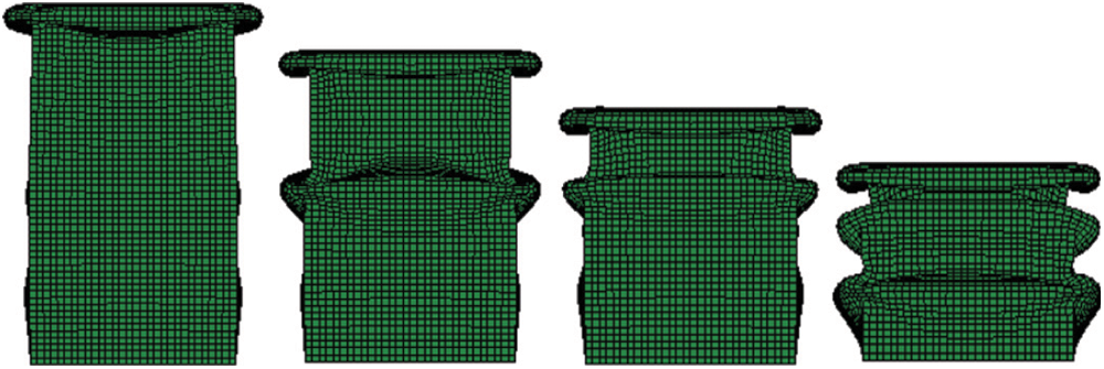
Figure 5: No SSNC deformation process of thin-walled embedded tubes
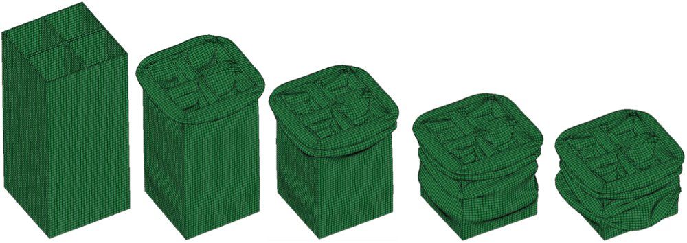
Figure 6: No SSNC of thin-walled embedded four-cell tubes
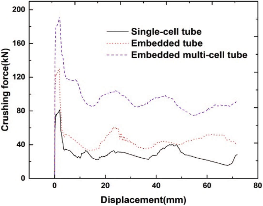
Figure 7: Displacement load curves of three types of tubes
By comparing the area enclosed by the displacement load curves of the three types of tubes in Fig. 7, the maximum impact load of the three types of tubes increases successively. From the numerical simulation results, it is concluded that the energy absorption of embedded four-cell tubes is much higher than that of the single tube and the embedded tube. Therefore, the embedded four-cell tubes is selected for surface nanocrystallization layout optimization in this paper.
4 Optimization Design for EMC Energy Absorption Structures with Local Surface Nanocrystallization
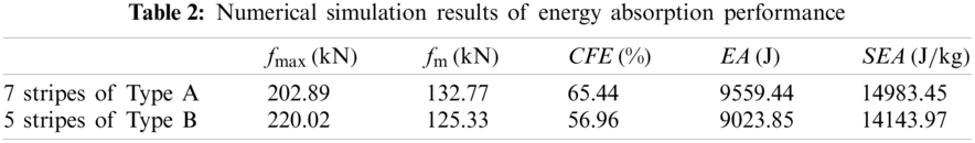
The optimal design of energy absorbing structure is to find the optimal parameters for energy absorbing performance with the aid of computer under the premise of setting constraints. The MMC method is used to optimize the number of nanocrystallized stripes on the surface of thin-walled structures, so as to improve the ability of absorbing impact kinetic energy in the impact process. The number of components (nanocrystallized stripes) affects collapse mode in the buckling process, and then makes an effort on the structural energy absorption. Consistent nanocrystallization components (CNC) are selected as the constraint functions, and the number of components is limited between 2 and 10. According to the nanocrystallization distributions of Type A and Type B, optimization results for the two different types are obtained and the displacement-load curves of models with different stripe numbers are displayed in Fig. 8 shows. Table 1 shows the energy absorption of the multi-cell tubes with two nanocrystallization distribution types, in which Type A has the highest energy absorption of 9559.44 J and Type B has the highest energy absorption of 9023.85 J.
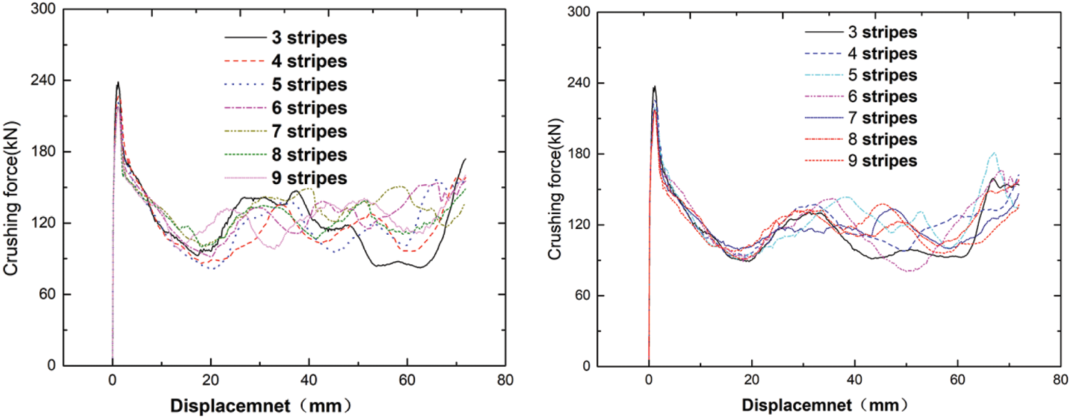
Figure 8: Displacement-load curves of two nanocrystallization distribution types
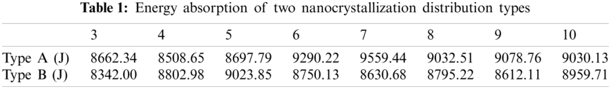
Fig. 9 shows the deformation modes of two different types of embedded nanocrystallized thin-walled structures in the whole crushing process, it is concluded that for the B type nanocrystallization distribution, the optimal design corresponds to the structure with five stripes. In the crushing process, the initial deformation occurs in the untreated part in the middle of the tube, while with the compression going on, buckling folds appear in the untreated upper part and compaction is observed subsequently. The folds are generated outwards in the upper and lower adjacent nanocrystallized areas and inward sunken deformation occurs in the untreated parts. For structures with Type A design, the optimal nanocrystallizaiton components for energy absorption structures corresponds to the equally distributed 7 stripes, with the increasing of stripe number, the upper part of the multi-cell structure buckles first and the nanocrystallized parts collapse, the energy absorption in the crushing process is increased. Through the analysis of the data in Table 2, the CFE of Type A design is enhanced by 8.48% compared with the 5 stripes design of Type B. The total energy absorption is 535.59 J higher than the 5 stripes design of Type B and 45.47% than that of the untreated embedded structure, which indicates that the energy absorption is dramatically improves for thin-walled embedded structure after SSNC.
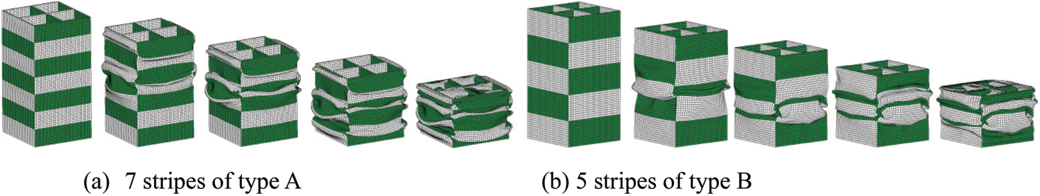
Figure 9: Deformation process of two nanocrystallization distribution types (a) 7 stripes of Type A (b) 5 stripes of Type B
As long as the component width is consistent, the optimal number of components (nanocrystallization stripe number) and the proportion of nanocrystallization areas with two different design types are determined. Release the component width constraint and select the disordered nanocrystallization components (DNC) as the optimization component, the above mentioned embedded four-cell structures with 7 equally distributed nanocrystallization layouts is further optimized, the local optimal solution is obtained in the geometric parameter design, and the energy absorption performance is further improved. By comparing the results with that of the CNC design, the accuracy of the design is further verified. In order to clearly observe the buckling path and evolution process of the structure, the buckling characteristics of the internal variation of the structure is shown in Fig. 10. Through analyzing the external and internal deformation characteristics of the thin-walled embedded structures, it is found that the deformation of the outer tube is symmetric and consistent with the inner tube, that is the untreated part deforms inwards. As the impact process proceeds, the symmetricity of inner and outer tube is more obvious. The plastic hinge appears in the untreated part area of the inner tube, which enlarges the plastic zone and improves the absorption of impact kinetic energy by the inner tubes. The plastic hinge of the embedded inner tube appears at the edges of the nanocrystallization component and the non nanocrystallization component, which is conducive to the gradual stability of the concave convex overlapping buckling modes and the improvement of the energy absorption performance.
From the Fig. 11, it is observed that the displacement-load curve has basically the same vibration trend before 20 mm for the two designs. While in the later stage of the impact process, the difference between the ordinates of the two curves increases, the area enclosed by the DNC curve and the coordinate axis is enlarged, which indicating that the energy absorption is further improved. From the results of local optimal solution in Table 3, it is observed that the energy absorption is increased by 50.78% compared to the untreated counterpart with the same geometric dimensions, and the CFE is much higher than that the untreated single tube and untreated embedded tube, which reflects better stability in the crushing process.
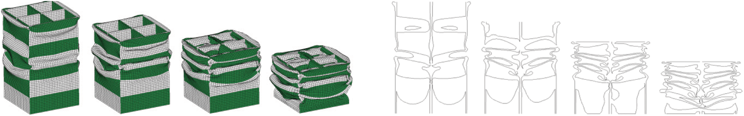
Figure 10: DNC deformation of embedded four-cell tubes
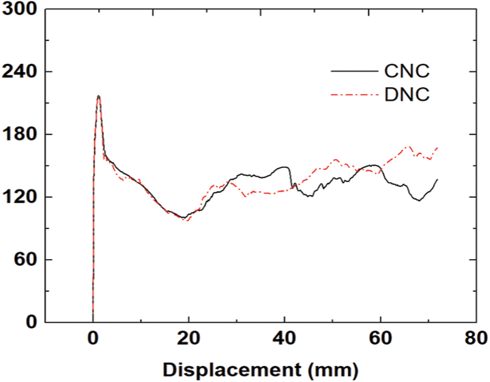
Figure 11: Optimized displacement load curves under different component types
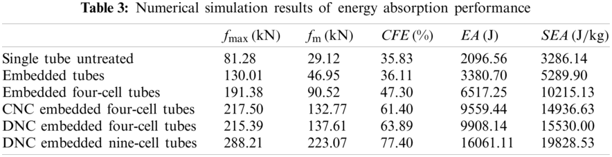
Based on the optimization results of nanocrystallization area ratio and nanocrystallization components of the thin-walled EMC energy absorption structures, the DNC embedded 9-cell structure is further investigated numerically. For the embedded 9-cell tube, there is a distribution state that provides more energy absorption than that of 7 stripe DNC distribution. When the 5 stripe DNC is distributed, when the nanocrystallization area at the top of the impacted end accounts for a large proportion, the specific energy absorption is 385.66 J/kg higher than that of the 7 stripe, but it is unstable in the process of impact and the impact load efficiency decreases. When the nanocrystallization components are inconsistent, the energy absorption changes with the number of iterations, as shown in Fig. 12. To clearly observe the deformation stages for the embedded 9-cell structure, the buckling deformation is exhibited in Fig. 13. For this structure, the deformation first occurs in the top and middle of the structure and the inner tubes show symmetric deformation mode. As the impact continues, the untreated part buckles inwards and the nanocrystallized part moves outwards. Finally, four folds with concave and convex phases are generated to control the buckling ripple of the structure to a certain extent. Compare its energy absorption properties with the embedded 4-cell thin-walled structure, the fmax of the 9-cell structure is increased and the impact process is stable, besides, the SEA is also increased by 27.68%. From the results, it is concluded that the SEA is significantly enhanced by optimizing the structural and nanocrystallization design.

Figure 12: Optimization iteration process curve
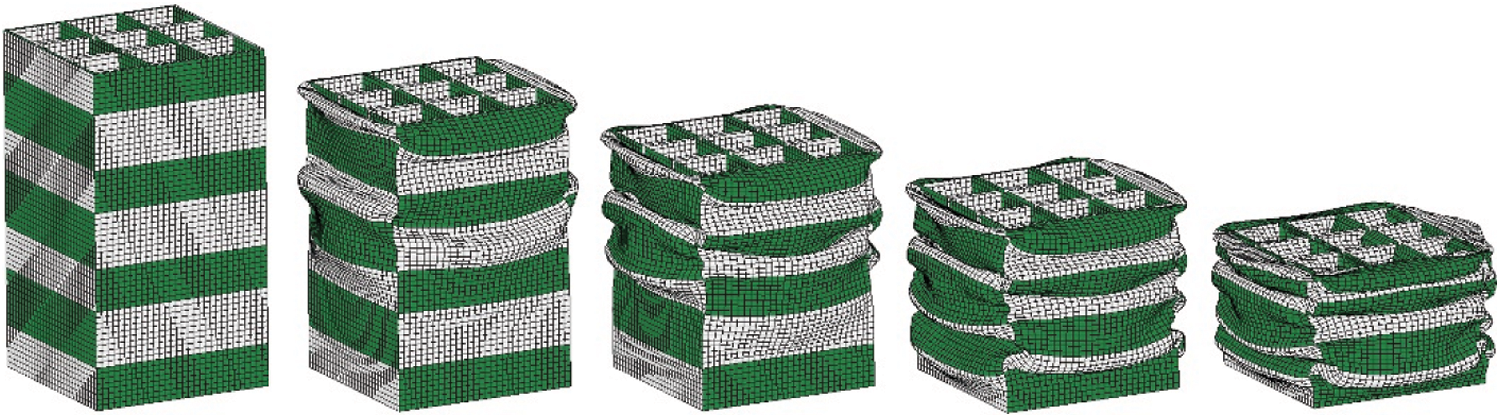
Figure 13: Deformation process of embedded nine-cell tubes
Due to the multi-layer problem in the multi-cell structures, a novel DNC clapboard type energy absorbing structure is proposed by selecting the DNC nanocrystallization layout and optimizing the number of nanocrystallization components. Fig. 14 shows the deformation process of the new DNC clapboard energy absorption structure. Compared with DNC type nine-cell tubes, the outside tube buckles first at the exit of the clapboard, under the action of the clapboard, the deformation of the inner tube in the first stage mainly occurs at the upper part of the clapboard, and the nanocrystallization region is symmetrical. Under the impact load, the outside tube and the inner embedded tubes in the upper part of the clapboard are gradually compacted. With the impact process, the inner tubes in the lower part of the clapboard deforms symmetrically and evenly. The nanocrystallization region of the outer tube bulges outward and the nanocrystallization region sinks inward. The specific energy absorption of this novel configuration is 3.61% higher than that of DNC embedded nine cell tubes.
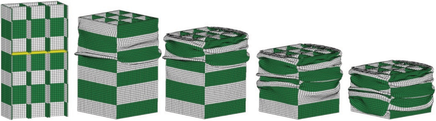
Figure 14: Deformation process of embedded clapboard type nine-cell tubes
In virtue of local surface nanocrystallization, the distribution of material properties and load-carrying capacity of the structure are changed, and the buckling deformation of the structure can be induced. Compared with the multi-cell thin-walled structure, the EMC thin-walled structure is more suitable for local surface nanocrystallization treatment and the processing is simple. Thus, method of MMC is used directly to optimize and design the nanocrystallization layouts on the local surface. In the design of EMC thin-walled structure, the local surface nanocrystallization distributions of the outer tube and the embedded inner tube can be diversified. The results show that the design scheme of the nanocrystallized area for the inner tube corresponding to the untreated part for the outer tube can coordinate the overall deformation, and this layout can be used as the basic design mode. The optimized numerical results proved that the SEA and CFE of the embedded 4-cell thin-walled structure with local surface nanocrystallization are 50.78% and 35.07% higher than those of the same structure without nanocrystallization. Moreover, compared with the optimized 4-cell structure, the SEA of the nanocrystallized embedded 9-cell tube structure under the same distribution is further increased by 27.68% and the CFE is enhanced by 21.15%. On account of the multi-layer problem in the multi-cell structure, a novel DNC clapboard type energy absorption structure is proposed. The specific energy absorption of this structure is 3.61% higher than that of DNC embedded 9-cell tube. The design method of EMC thin-walled structure with local surface nanocrystallization provides a guidance for the design of new energy absorption devices.
Funding Statement: In this research work, Dalian Innovation Foundation of Science and Technology (2018J11CY005) and State Key Laboratory of Structural Analysis for Industrial Equipment (S18313) are gratefully acknowledged.
Conflicts of Interest: The authors declare that they have no conflicts of interest of report regarding the present study.
1. Chouw, N., Jayaraman, K., Yan, L. B. (2014). Lateral crushing of empty and polyurethane-foam filled natural flax fabric reinforced epoxy composite tubes. Composites Part B: Engineering, 63(4), 15–26. DOI 10.1016/j.compositesb.2014.03.013. [Google Scholar] [CrossRef]
2. Sun, G. Y., Li, S. F., Li, G., Li, G. Y., Li, Q. (2016). Experimental study on crashworthiness of empty/aluminum foam/honeycomb-filled CFRP tubes. Composite Structures, 152(11), 969–993. DOI 10.1016/j.compstruct.2016.06.019. [Google Scholar] [CrossRef]
3. Zhu, G. H., Wang, Z., Huo, X. T., Cheng, A. G., Li, G. Y. et al. (2017). Experimental and numerical investigation into axial compressive behaviour of thin-walled structures filled with foams and composite skeleton-Science Direct. International Journal of Mechanical Sciences, 122(1), 104–119. DOI 10.1016/j.ijmecsci.2016.12.019. [Google Scholar] [CrossRef]
4. Yamashita, M., Gotoh, M., Sawairi, Y. (2003). Axial crush of hollow cylindrical structures with various polygonal cross-sections: Numerical simulation and experiment. Journal of Materials Processing Technology, 140(1), 59–64. DOI 10.1016/S0924-0136(03)00821-5. [Google Scholar] [CrossRef]
5. Tang, Z., Liu, S. T., Zhang, Z. H. (2012). Energy absorption properties of non-convex multi-corner thin-walled columns. Thin-Walled Structures, 51(1), 112–120. DOI 10.1016/j.tws.2011.10.005. [Google Scholar] [CrossRef]
6. Fan, Z., Lu, G., Liu, K. (2013). Quasi-static axial compression of thin-walled tubes with different cross-sectional shapes. Engineering Structures, 55(4), 80–89. DOI 10.1016/j.engstruct.2011.09.020. [Google Scholar] [CrossRef]
7. Xu, X. S., Zhao, Z., Wang, W., Tong, Z. Z., Zhou, Z. H. et al. (2021). A novel design of thin-walled energy absorption structures with local surface nanocrystallization. Thin-Walled Structures, 160(2), 107337. DOI 10.1016/j.tws.2020.107337. [Google Scholar] [CrossRef]
8. Daneshi, G. H., Hosseinipour, S. J. (2002). Grooves effect on crashworthiness characteristics of thin-walled tubes under axial compression. Materials & Design, 23(7), 611–617. DOI 10.1016/S0261-3069(02)00052-3. [Google Scholar] [CrossRef]
9. Li, G. Y., Xu, F. X., Sun, G. Y., Li, Q. (2015). A comparative study on thin-walled structures with functionally graded thickness (FGT) and tapered tubes withstanding oblique impact loading. International Journal of Impact Engineering, 77(3), 68–83. DOI 10.1016/j.ijimpeng.2014.11.003. [Google Scholar] [CrossRef]
10. Zhang, X., Zhang, H. (2013). Energy absorption of multi-cell stub columns under axial compression. Thin-Walled Structures, 68, 156–163. DOI 10.1016/j.tws.2013.03.014. [Google Scholar] [CrossRef]
11. Zhou, C. H., Jiang, L. L., Bai, X. J., Tian, K. (2017). Origami crash boxes subjected to dynamic oblique loading. Journal of Applied Mechanics, 84(9), 10. DOI 10.1115/1.4037160. [Google Scholar] [CrossRef]
12. Zhang, X., Leng, K., Zhang, H. (2017). Axial crushing of EMC tubes. International Journal of Mechanical Sciences, 131–132, 459–470. DOI 10.1016/j.ijmecsci.2017.07.019. [Google Scholar] [CrossRef]
13. Sharifi, S., Shakeri, M., Fakheri, H., Bodaghi, M. (2015). Experimental investigation of bitubal circular energy absorbers under quasi-static axial load. Thin-Walled Structures, 89, 42–53. DOI 10.1016/j.tws.2014.12.008. [Google Scholar] [CrossRef]
14. Gong, C., Bai, Z. H., Lv, J. Y., Zhang, L. W. (2020). Crashworthiness analysis of bionic thin-walled tubes inspired by the evolution laws of plant stems. Thin-Walled Structures, 157(5), 107081. DOI 10.1016/j.tws.2020.107081. [Google Scholar] [CrossRef]
15. Liu, Y. (2008). Crashworthiness design of multi-corner thin-walled columns. Thin-Walled Structures, 46(12), 1329–1337. DOI 10.1016/j.tws.2008.04.003. [Google Scholar] [CrossRef]
16. Zhang, X., Wen, Z. Z., Zhang, H. (2014). Axial crushing and optimal design of square tubes with graded thickness. Thin-Walled Structures, 84, 263–274. DOI 10.1016/j.tws.2014.07.004. [Google Scholar] [CrossRef]
17. Yin, H. F., Wen, G. L., Liu, Z. B., Qing, Q. X. (2014). Crashworthiness optimization design for foam-filled multi-cell thin-walled structures. Thin-Walled Structures, 75, 8–17. DOI 10.1016/j.tws.2013.10.022. [Google Scholar] [CrossRef]
18. Wang, H., Ma, Z., Kikuchi, N., Pierre, C., Raju, B. (2004). Multi-domain multi-step topology optimization for vehicle structure crashworthiness design. Sae World Congress & Exhibition, pp. 12. Detroit, Michigan. [Google Scholar]
19. Chen, A., Liu, J. B., Wang, H. T., Lu, J., Wang, Y. M. (2016). Gradient twinned 304 stainless steels for high strength and high ductility. Materials Science and Engineering, 667, 179–188. DOI 10.1016/j.msea.2016.04.070. [Google Scholar] [CrossRef]
20. Wu, G., Chan, K. C., Zhu, L. L., Sun, L. G., Lu, J. (2017). Dual-phase nanostructuring as a route to high-strength magnesium alloys. Nature, 545(7652), 80–83. DOI 10.1038/nature21691. [Google Scholar] [CrossRef]
21. Tao, N. R., Wang, Z. B., Tong, W. P., Sui, M. L., Lu, J. et al. (2002). An investigation of surface nanocrystallization mechanism in Fe induced by surface mechanical attrition treatment. Acta Materialia, 50(18), 4603–4616. DOI 10.1016/S1359-6454(02)00310-5. [Google Scholar] [CrossRef]
22. Chen, A. Y., Ruan, H. H., Wang, J., Chan, H. L., Wang, Q. et al. (2011). The influence of strain rate on the microstructure transition of 304 stainless steel. Acta Materialia, 59(9), 3697–3709. DOI 10.1016/j.actamat.2011.03.005. [Google Scholar] [CrossRef]
23. Roland, T., Retraint, D., Lu, K., Lu, J. (2007). Enhanced mechanical behavior of a nanocrystallised stainless steel and its thermal stability. Materials Science & Engineering A, 445(6), 281–288. DOI 10.1016/j.msea.2006.09.041. [Google Scholar] [CrossRef]
24. Yang, X. J., Wang, X. Y., Ling, X., Wang, D. (2017). Enhanced mechanical behaviors of gradient nano-grained austenite stainless steel by means of ultrasonic impact treatment. Results in Physics, 7, 1412–1421. DOI 10.1016/j.rinp.2017.04.002. [Google Scholar] [CrossRef]
25. Tang, T., Gao, Y., Lu, Y., Li, Y., Lu, J. (2018). Development of high-performance energy absorption component based on the structural design and nanocrystallization. Materials & Design, 137, 214–225. DOI 10.1016/j.matdes.2017.10.002. [Google Scholar] [CrossRef]
26. Guo, X., Zhang, W. S., Zhong, W. L. (2014). Doing topology optimization explicitly and geometrically—A new moving morphable components based framework. Journal of Applied Mechanics, 81009(8), 197. DOI 10.1115/1.4027609. [Google Scholar] [CrossRef]
27. Zhang, W. S., Yuan, J., Zhang, J., Guo, X. (2016). A new topology optimization approach based on moving morphable components (MMC) and the ersatz material model. Structural & Multidisciplinary Optimization, 53(6), 1243–1260. DOI 10.1007/s00158-015-1372-3. [Google Scholar] [CrossRef]
28. Zhang, W. S., Jiang, S., Liu, C., Li, D., Kang, P. et al. (2020). Stress-related topology optimization of shell structures using IGA/TSA-based moving morphable void (MMV) approach. Computer Methods in Applied Mechanics and Engineering, 366, 113036. DOI 10.1016/j.cma.2020.113036. [Google Scholar] [CrossRef]
 | This work is licensed under a Creative Commons Attribution 4.0 International License, which permits unrestricted use, distribution, and reproduction in any medium, provided the original work is properly cited. |