| Computer Modeling in Engineering & Sciences |
DOI: 10.32604/cmes.2022.018004
ARTICLE
Localization of Mobile Robot Aided for Large-Scale Construction Based on Optimized Artificial Landmark Map in Ongoing Scene
1Shanghai Key Laboratory of Intelligent Manufacturing and Robotics, School of Mechatronic Engineering and Automation, Shanghai University, Shanghai, 200444, China
2National Demonstration Center for Experimental Engineering Training Education, Shanghai University, Shanghai, 200444, China
*Corresponding Author: Shuai Guo. Email: guoshuai@i.shu.edu.cn
Received: 22 June 2021; Accepted: 28 September 2021
Abstract: The effectiveness of mobile robot aided for architectural construction depends strongly on its accurate localization ability. Localization of mobile robot is increasingly important for the printing of buildings in the construction scene. Although many available studies on the localization have been conducted, only a few studies have addressed the more challenging problem of localization for mobile robot in large-scale ongoing and featureless scenes. To realize the accurate localization of mobile robot in designated stations, we build an artificial landmark map and propose a novel nonlinear optimization algorithm based on graphs to reduce the uncertainty of the whole map. Then, the performances of localization for mobile robot based on the original and optimized map are compared and evaluated. Finally, experimental results show that the average absolute localization errors that adopted the proposed algorithm is reduced by about 21% compared to that of the original map.
Keywords: Large-scale construction; artificial landmark map; localization; mobile robot; non-linear optimization
Faced with the large-scale construction for complex structures, the localization of mobile robot plays a key role in the quality of buildings. Especially in structured/unstructured environments of the construction industry, new capabilities that combining technologies of Additive Manufacturing (AM, also known as 3D printing) and mobile robotics are explored to improve the production efficiency and level of automation. Generally, 3D printing processes can be mainly classified into three kinds, including the Contour Crafting [1], Concrete printing [2] and D-shape [3]. The Contour Crafting and Concrete printing are based on the extruded form with different nozzles to complete the printing of the buildings, while D-shape is a process where the power materials are deposited as objects by the binder. As a result, the large-scale 3D printing process for buildings was investigated [4], and the corresponding robotic system are developed, including mainly the cable-driven parallel robot [5–8], vehicle-mounted robot [9] and mobile robotics [10–14]. The structure installations of cable-driven parallel robot and vehicle-mounted robot are time-consuming and laborious, and their structural sizes are always the restrictions to the accuracy of large-scale printings. So, the mobile robotics that integrated the manipulator and mobile platform is gradually developed to complete the large-scale printing instead of the formers. It can easily print structures with any shapes and sizes, and effectively avoids the trouble of installation. However, the mobility of mobile robotics also results in a huge uncertainty of localization in large-scale construction scenes. Ignoring the error of the manipulator, the printing quality and efficiency of buildings are indirectly determined by the localization accuracy of the mobile robot. In addition, due to the architectural scene is unstructured and featureless, which poses a huge challenge to an accurate localization of mobile robot.
On related works, the relevant localization techniques of mobile robot were reviewed in detail. Generally speaking, the localization approach was mainly classified into two ways, nature features [15,16] and artificial landmarks [17,18]. However, the heavy computational burden and uncertainty of the nature features could perform a poor localization of the mobile robot. So, an artificial landmark was well suitable to handle the probabilistic uncertainty and the landmark-based representation could be well-adapted to the large-scale environment [19,20]. Also, a multi angle intersection algorithm was established to achieve an accurate measurement in the position and orientation of mobile robot for large-scale scenes [21], and the factors that affecting the uncertainty of landmarks were critically analyzed. Firstly, the uncertainty of landmarks was represented by Gaussian distribution to present the localization error of mobile robot [22]. Then, the uncertainty of localization parameters was minimized by a cost function, and the landmark selection problem was translated into a Semi-Definite Programming representation [23]. The localization error was relevant to the configuration of the visible landmarks, and a suitable landmark could reduce it [24]. Similarly, the sensitivity of absolute positioning techniques to the landmark configuration and noisy data were analyzed to improve the accuracy of the vehicle’s navigation [25]. A landmark placement method was also proposed to calculate indistinguishable landmark configurations to reduce the ambiguity of the whole environment [26]. Furthermore, the optimization technologies were also proposed by scholars to reduce the uncertainty errors of landmarks. Firstly, a simulated annealing technique was adopted to find the landmark configuration that maximizes the number of the regions [27]. Then, the environment was decomposed into a number of sized regions, and a novel graph theoretic formulation was introduced to select the optimal number of landmarks [28]. A landmark was designed and the candidate area was also detected by a double-layer recognition algorithm to achieve the accurate localization [29]. Besides, a Markov probabilistic positioning method was simulated by the maximum statistical power provided by the concept of artificial landmarks [30], and the Markov localization method that equipped with a discrete Bayesian filter was adopted to calculate of the probability distribution of the entire state space [31]. In addition, multi-sensor fusion that fused the Inertial Measurement Unit (IMU) sensor, odometry and Lidar module is another way to improve robot localization and navigation [32]. Then, the artificial neural network and three-layer neural network are further adopted based on it [33,34]. Due to the uncertainty of the data sampling period of the sensor, the extended unbiased finite-impulse response (EFIR) filter was presented to complete an accurate localization by about 10.2% [35]. Lastly, for the issue of insufficient localization safety with landmarks, a landmark augmentation method was introduced to identify the minimum place where landmarks could be added [36].
Contrary to the above approaches, simultaneous localization and mapping (SLAM) technology has becoming widely used in autonomous robotics [37,38]. To improve the accuracy and efficiency of mapping and localization for mobile robot, a Monte Carlo reinforcement learning was proposed to obtain the optimal strategy [39]. Then, the recognizable artificial landmarks were selected to establish data associations and improve the accuracy of mapping. Similarly, an Unscented Kalman Filter (UKF) was also applied into SLAM and the Monte-Carto reinforcement learning was used to obtain a landmark selection policy [40]. Besides, an entropy-based feature selection strategy was developed to minimize the entropy to estimate the location errors of the mapping and robot [41]. However, the above approaches brough the computational burden and memory constraints for real time SLAM, and they had limitations to the large-scale and dynamic construction environment. In addition, a perfect match approach was proposed to realize the robot self-localization, and it can perform a high accuracy, robustness and computational efficiency [42,43]. However, it was tested based on natural landmarks, and it was not used to optimize the accuracy of the artificial landmark map to improve the robot’s self-localization. Also, a localization approach RLmPFL (Reinforcement-learning based mapping in a Particle-filter based localization) was regarded as a complementary module for SLAM to realize a more reliable update for indoor long-term localization [44].
For further improving the localization accuracy of mobile robot, a localization solution that based on the building plan was also studied. Firstly, architectural floor plans were easily understood by non-expert users and they typically represented the non-rearrangeable parts of buildings. When the globally consistent map was aligned to the computer-aided design (CAD) drawing, the robot localization could be estimated by the global reference frame of the floor plan in indoor industrial scenarios [45]. Similarly, A pose-graph with Lidar measurements that represented by a SLAM and the floor plan was proposed, and the robot localization system that assisted by architectural CAD drawings could achieve a sub-centimeter accuracy [46]. Moreover, a novel method for high-accuracy localization based on the state of the known building structure was presented [47], and the synchronization of building information with the robot’s map accelerated to the process of mobile construction [48]. In our previous work, an adaptive robust localization method based on artificial landmarks and generated buildings was also studied [49].
As mentioned above, the approaches of accurate localization for mobile robot were discussed, and the localization of mobile robot based on a set of reflectors and SLAM was also applied into the construction of on-site or off-site [12,13]. However, the impact of an artificial landmark map on the localization of mobile robot for large-scale construction has not been fully studied. Meanwhile, the accuracy of environmental map in large-scale ongoing scenes was not easy to be measured directly. Therefore, the paper would study the localization performance of mobile robot by optimizing uncertainties of the large-scale artificial landmark map, and the built map was evaluated by the motion trajectory of mobile robot [50–53].
Motivated by the uncertainty problems for large-scale mapping and localization in an unstructured and featureless construction environment, an artificial landmark map that constrained by a two-dimensional building plan is built. Assuming that the artificial landmark map does not exist symmetrical ambiguity, and the building plan is mapped to the construction site 1:1 vertically. Then, the whole environmental map is optimized by a method of non-linear optimization based on graphs, and the localization accuracy of mobile robot is further analyzed and evaluated.
The main contribution of the paper is to solve the localization accuracy problem of mobile robot for large-scale construction by considering the uncertainty of the artificial landmark map with a non-linear optimization algorithm based on graphs. According to our knowledge, we have not found the present literatures to study this issue in a large-scale construction scene by creating an artificial landmark map. So, a mobile 3D printing construction robot model that integrated the robotics technology and 3D printing technology is developed to achieve a large-scale construction by us. Due to the large-scale and featureless in construction scene, a large-scale environmental model that combining the artificial landmarks with the building plan is built. Then, each artificial landmark is regarded as a node of graphs, and all artificial landmarks are connected to form an artificial landmark map. In addition, considering the uncertainty of the artificial landmark map, a novel non-linear optimization algorithm based on graphs is further proposed to improve the accuracy of global map. Lastly, the optimized result of the artificial landmark map is compared to the original, and the localization errors of mobile robot that based on the optimized map are evaluated by high-precision sensors.
The remainder of this paper is organized as follows. We first briefly introduce the pipeline of large-scale construction and the mobile robot model (Section 2). Then, we build an environmental model integrated the artificial landmarks with the building plan, and propose a novel non-linear optimization algorithm based on graphs to reduce the uncertainty of constructed map. Next, we introduce the map matching for artificial landmarks and the global localization of mobile robot (Section 3). Furthermore, the experiments for localization of mobile robot in designated station are compared (Section 4) and the experimental results that obtained from the tests are evaluated (Section 5). Finally, the paper concludes with an outlook to future research in ongoing scene (Section 6).
2 Problem Formulation and Mobile Robot System
In this section, the localization accuracy problem of mobile robot aided for large-scale construction is proposed, and the pipeline of large-scale construction based on the mobile robot is also introduced. Lastly, it is presented the mobile robot system that including the hardware platform and software architecture used as this experimental platform.
A large-scale building that constructed itself has the attribute of “additive” generally. Originally, the built environment is relatively empty, and the environmental information will increase with the process of construction. In our previous work, the construction scene is defined as an “ongoing scene” and the mobile robot can achieve the ongoing construction according to the sequence of planned missions [47]. However, the extracted features in the ongoing scene are almost non-existent, which fails to realize the localization of mobile robot. So, the artificial landmark map is necessary to be built in the large-scale construction in advance. In addition, due to the uncertainty of measurement, it is more difficult to create an accurate map in a large-scale ongoing scene. As a result, an accurate map is vital to the localization performance of mobile robot, and it also indirectly affects the construction quality of the building.
2.2 Pipeline of Large-Scale Construction Based on Mobile Robot
As shown in Fig. 1, the system mainly includes two parts, including the building of artificial landmark map and real-time localization based on the planned route of tasks. Firstly, the artificial landmarks are constrained by a two-dimensional (2D) architectural plan, and the composition of them is called as a prior map of the construction scene. Then, each artificial landmark is regarded as a node of the probability graph model, and the uncertainty representation of the landmark was reduced by the non-linear optimization based on graphs. Furthermore, the local features of the artificial landmark map are extracted and matched with the global map, and the localization of mobile robot is realized by a triangular measurement algorithm based on least squares. Lastly, the localization results in designated stations are evaluated by three-dimensional (3D) motion capture system, which demonstrates the effectiveness of the optimized map.
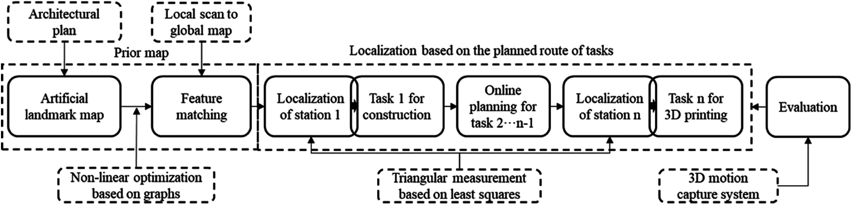
Figure 1: Pipeline of an artificial landmark map and localization of mobile robot for large-scale construction
2.3 Mobile Robot System for Large-Scale Construction
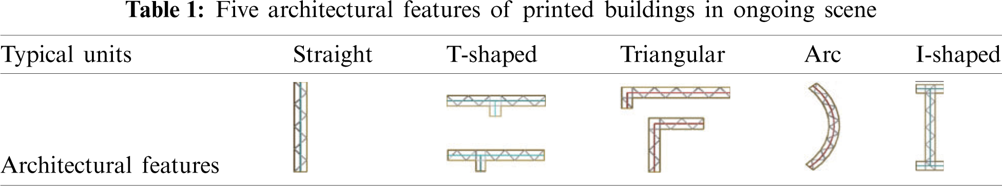
Due to the large-scale of the construction scene, the whole printed building is divided into five types of architectural units. As shown in Table 1, they mainly include the straight, T-shaped, I-shaped, triangular and arc unit. Then, the different typical units make up a complete model of the building.
For achieving the large-scale 3D printing of buildings, a mobile construction robot system is designed in detail. As shown in Fig. 2, the system mainly includes the following hardware parts, such as mobile construction robot, pouring device and some distance and angle sensors. Among them, the mobile robot system is composed of a 6-dof KUKA manipulator, an omnidirectional mobile platform with two Pepperl + Fuchs R2000 2D laser scanners and the operation control system (such as KR C4 controller and Beckhoff module). The workspace of KUKA manipulator can be up to 3095 mm, and the maximum load of it is 90 kg. Also, the two P + F R2000 laser scanners that equipped with an inertial measurement unit (IMU) are set on the diagonal edge of the omnidirectional mobile platform to realize the autonomous localization and navigation for the construction robot. They can rotate anticlockwise with 360 degrees in the resolution of 0.1 degrees. The fourteen ultrasonic sensors and an inclination sensor are also equipped with the mobile robot to achieve the obstacle avoidance and overturning detection. Similarly, a monocular camera and four supporting legs are installed to monitor the 3D printing process and ensure the stability of the robot during printing, respectively. Lastly, the laptop that acts as a main controller comprises an Intel Core (TM) i5-8300H CPU@2.30 GHz, 8 GB RAM, and all the sensors that mentioned above are connected to it.
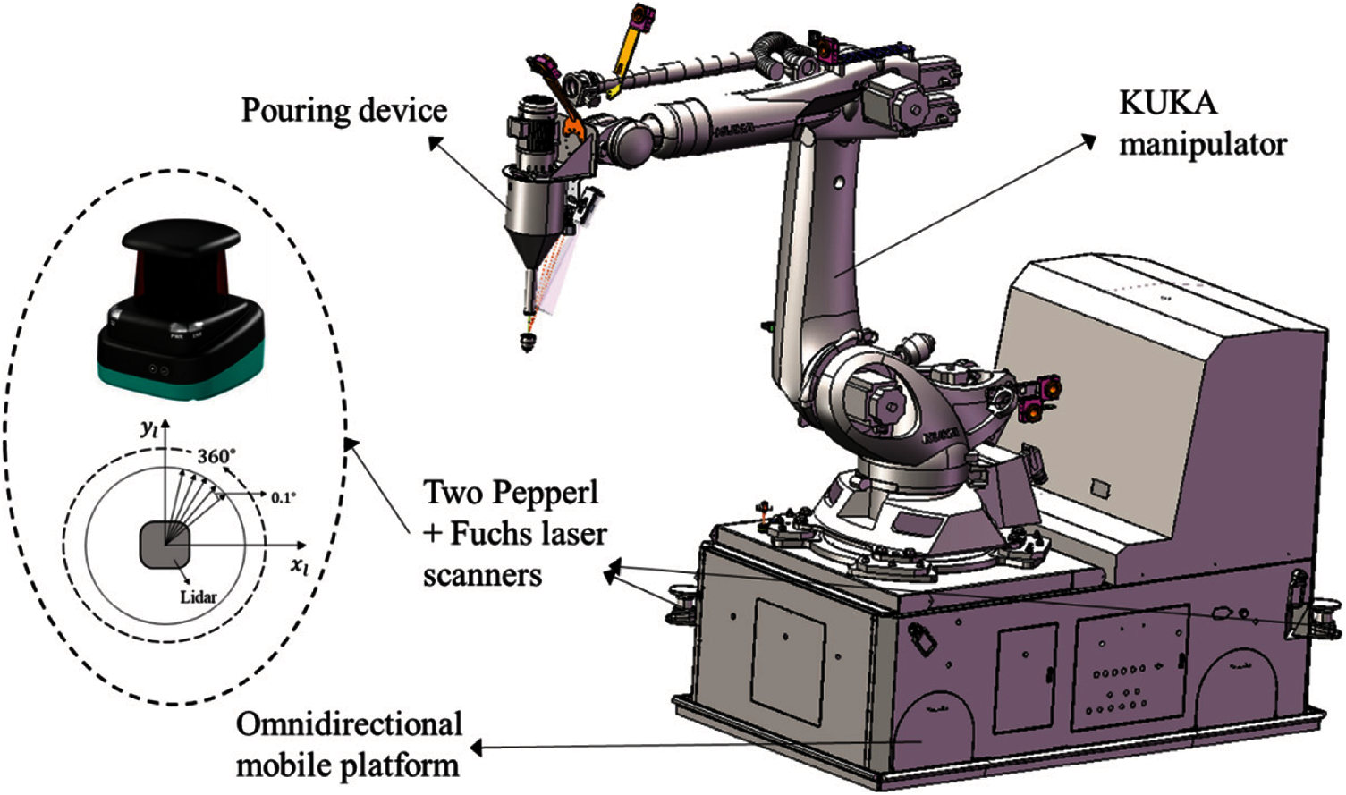
Figure 2: The structure of mobile construction robot and its main components
After the sensors are equipped with the mobile construction robot system, the software parts of the mobile construction robot system are built relatively. As shown in Fig. 3, the software mainly includes the upper computer, central computer and lower computer. The upper computer is developed in a laptop, and it can via the Transmission Control Protocol (TCP) to send task instructions. Then, the central computer acts as a server, parses the request command sent by the upper computer and gives a response. The central computer mainly includes four modules, such as the communication module between upper computer and central computer, mapping and localization module, autonomous navigation module and control module of mobile robot. The communication module between upper computer and central computer mainly includes some Application Programming Interfaces (APIs), such as control API, navigation API, status API and other APIs, and it can communicate with the upper computer through the windows socket. The mapping and localization module is to realize the localization of mobile robot by perceiving the information of the external environment through laser sensors. The function of the autonomous navigation module is to find the shortest or optimal path, and moves to the designated station without collision. The control module of mobile robot is to complete data interaction, and responds to the request task of the upper computer and updates the periodic data of the lower computer in real time. If the request command is the status information, the central computer can directly feedback, while the request command is the motion control information, it needs to be processed by the central computer and then sent to the lower computer for execution. Lastly, the lower computer software is developed by the Beckhoff module. When the Beckhoff controller receives the command, it transmits the odometry and IMU data to the central computer software by the Advanced Design System (ADS) communication and then feedbacks it to the upper computer software.
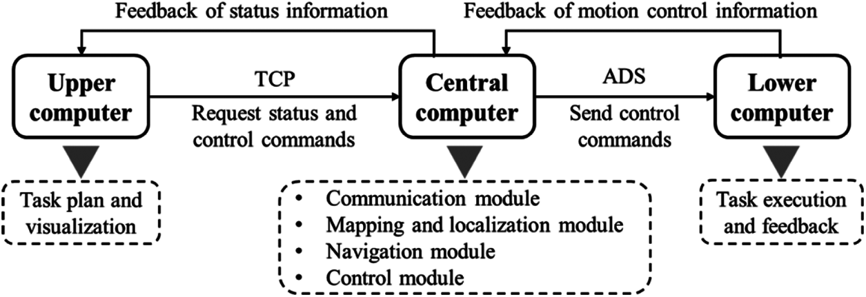
Figure 3: Software architecture of mobile robot system for large-scale construction
3 Methods of Mapping and Localization
In order to achieve the construction of buildings based on mobile construction robot, an artificial landmark map and localization method are proposed and illustrated in Fig. 4.
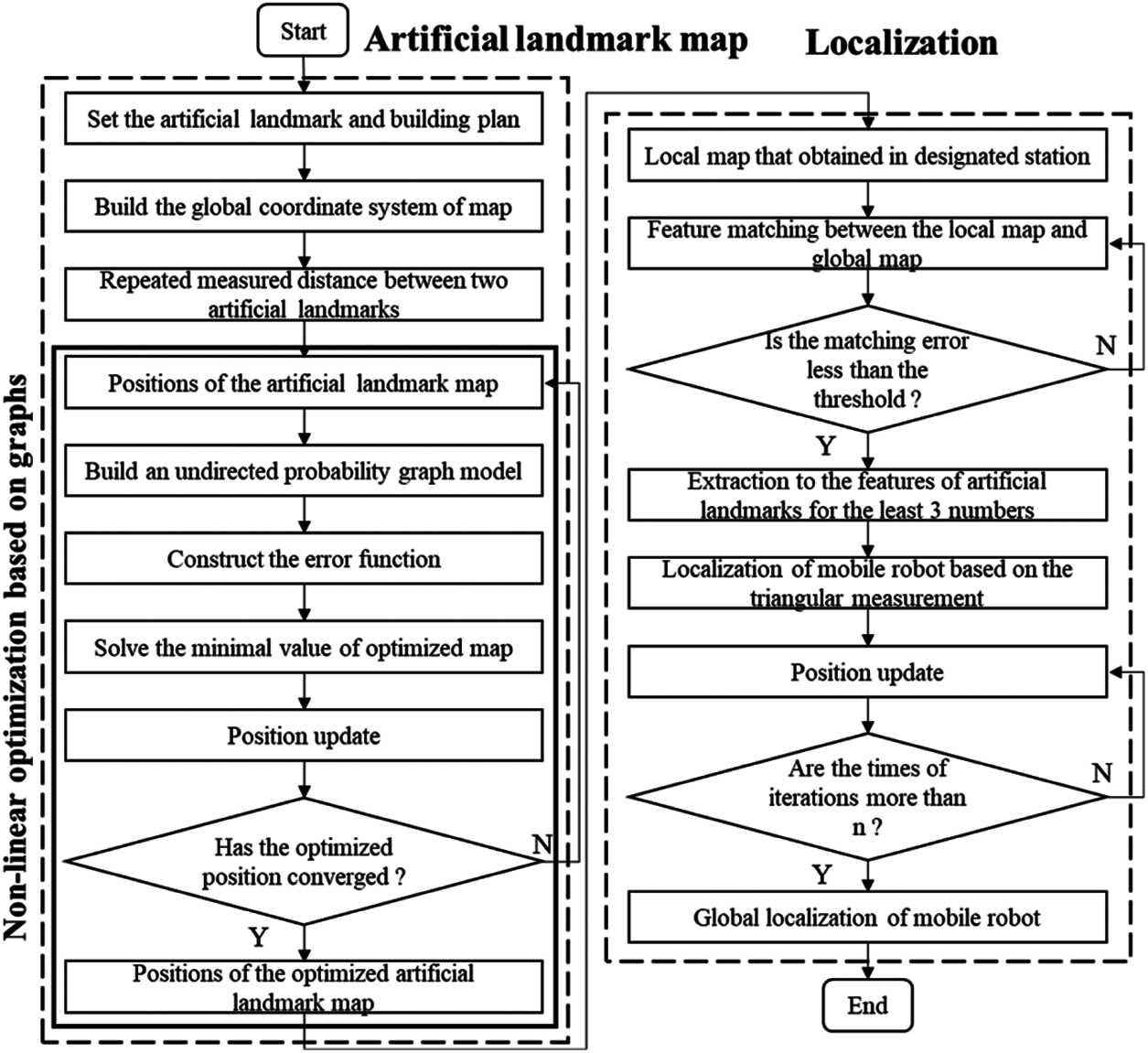
Figure 4: Flow diagram of an artificial landmark map and localization method
From above Fig. 4, it mainly includes: (1) Set the artificial landmark around the building plan, and build the global coordinate system; (2) Initialize the position of artificial landmarks in the global coordinate system; (3) Do the following steps for building the precise artificial landmark map. Firstly, build a probability graph model by connecting each artificial landmark, then, construct the objective function to obtain the optimal position of the map, lastly, calculate the position error and algorithm terminates if the optimized value converges to the threshold; otherwise, return to Step; (2). (4) Scan the local features of artificial landmarks and match to global map; (5) The matching succeeds if the matching error is less than the thresholds; otherwise, return to Step (4); (6) Extract the features of artificial landmarks with numbers of at least 3, and calculate the global localization of the mobile robot; (7) Position update; (8) Calculate the global localization result, and the algorithm terminates if the times of iterations are more than n; otherwise, return to Step (7).
The artificial landmark map is consisted of cylindrical reflectors, and each reflector is attached with the high reflective film. As shown in Fig. 5, the reflectors are denoted by
where the parameters
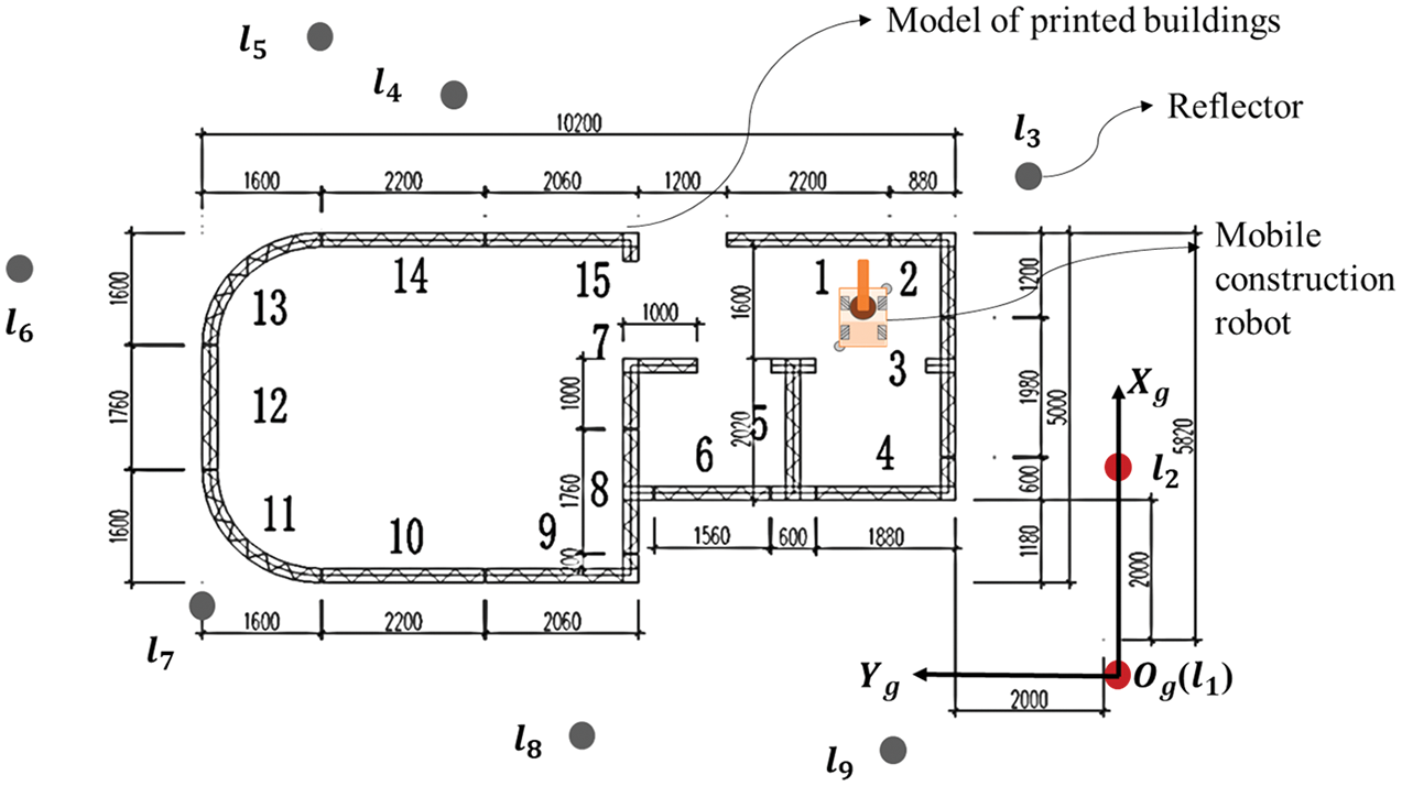
Figure 5: Building of the artificial landmark map in a large-scale ongoing scene
3.1.1 Position Estimations of Artificial Landmarks
Faced with the large-scale printing of buildings, the primary task is to construct an accurate map. As shown in Fig. 6, assuming the coordinate value of red reflectors
where
Finally, the positions of the unknown artificial landmarks are estimated from the above constraint Eqs. (2) and (3).
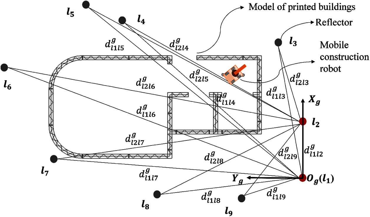
Figure 6: Initial position estimations of unknown reflectors
3.1.2 Building of Artificial Landmark Map Based on the Nonlinear Graph Optimization
Firstly, the coordinate values
From above Fig. 7, the nine reflectors are set in the ongoing scene, and the side of any two nodes is also measured. Then, the nonlinear equations between them can be described as
where
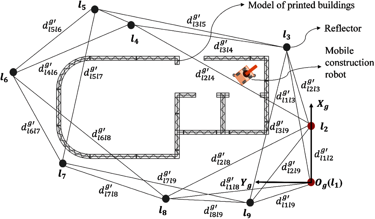
Figure 7: Optimization to the positions of reflectors based on a graph model
To improve the accuracy of artificial landmark map, the fourteen functions are built to calculate the coordinate values
where
In order to eliminate the uncertainty error of artificial landmark map, the optimal accurate value
where the objective function
Then, the optimal coordinate values of remaining reflectors
where the minimal value of
Furthermore, the decline factor
where the parameter
As a result, the optimized variable value
where the parameter variable
3.2 Localization of Mobile Robot Based on the Optimized Map
Localization is a fundamental requirement for mobile robot, especially for printing the architectural units from different stations. In addition, the odometry cannot provide the accurate pose due to the long-term cumulative error. Therefore, the artificial landmark and the Lidar are set in the scene, and the localization of designated station can be compensated by matched features with the global map. As a result, the accurate localization of mobile robot can be improved, which greatly reduces the calibration time of the manipulator for printing buildings later.
3.2.1 Map Matching for Artificial Landmarks
Firstly, the artificial landmarks are attached with the high-reflective film, and the scanned intensity values of them can be extracted by Lidars. Then, the local map is matched with the global map, and the current localization of mobile robot can be obtained. When the scanned reflectors are not less than three numbers, the robot can successfully achieve its localization by the trilateral measurement algorithm. Therefore, when the number of scanned reflectors is three, the features of identified reflectors are extracted to match with the global map. Also, when the number of reflectors is more than 3, the four reflectors that observed by the Lidars are selected to match with the global map.
As shown in Fig. 8a, the number of
where the parameters
where the parameter
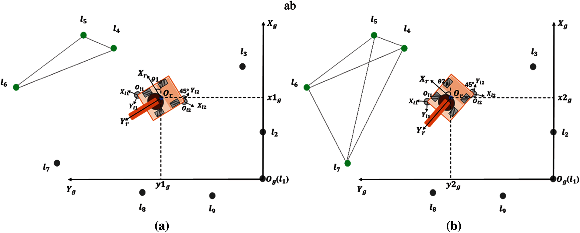
Figure 8: The global map and the local scanned map of the robot. (a) The number of scanned reflectors is 3 (b) The number of scanned reflectors is more than 3
In order to achieve the localization
When the number of scanned reflectors is more than 3, the features of any four reflectors are extracted to match with the global map. As shown in Fig. 8b, the reflectors
where the variables
As a result, the local scanned matching parameters are compared with the matching parameters that exist in global map. When the minimum value of the differences between them meets the following function (18), it is successful to match.
where the thresholds of angle errors and distance errors are denoted as
3.2.2 Localization of Mobile Robot Based on the Triangular Measurement
After the artificial landmarks are successfully matched with the global map, the localization of the mobile robot will be estimated accurately. However, due to the measurement errors of Lidar sensors, the paper adopts the repeated measurement value to obtain the accurate pose of mobile robot. Then, the triangular measurement method based on the least square is also adopted [55,56].
As shown in Fig. 9, the features of three reflectors
where the global coordinate of the robot and reflectors are represented as
Then, the localization
Among them, the parameter matrix
and the direction angle
where the parameter
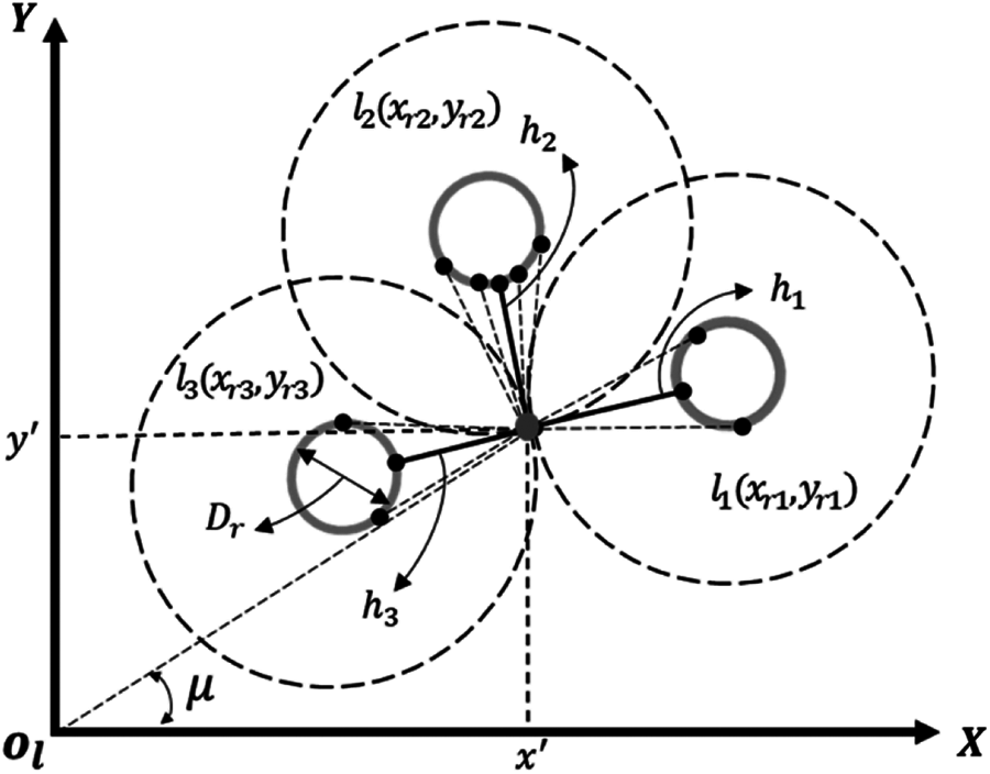
Figure 9: Trilateral positioning method based on the repeated measurements
Due to the large area of the ongoing scene, the truth of the artificial landmark map was difficult to be measured directly. To validate the effectiveness of the optimized map, the localization of mobile robot in designated station was evaluated. So, the experimental preparation and the designed route were introduced in detail, and the real-time localization for mobile 3D printing construction robot from 15 stations were also tested.
4.1 Overall Route and Experimental Preparation
The length and width of mobile platform were 2.4 m and 1.4 m. Specifically, multiple types of sensors were equipped with the mobile construction robot to achieve the localization and navigation, including two Pepperl + Fuchs laser scanners, wheel encoders, an IMU, an inclinometer and sixteen ultrasounds. As shown in Fig. 10, the nine reflectors
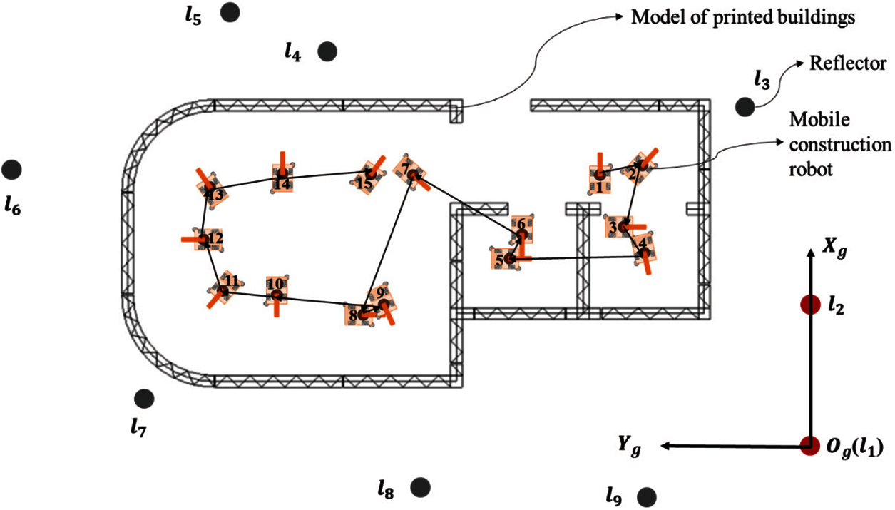
Figure 10: The route of 15 stations for large-scale construction based on the mobile robot
In order to verify the localization accuracy of mobile robot, a building plan with the length and width of 10.2 and 4.96 m was mapped in the scene by 1:1 ratio. Then, the 9 reflectors were placed in the scene to realize the localization of mobile robot. The center of the reflector
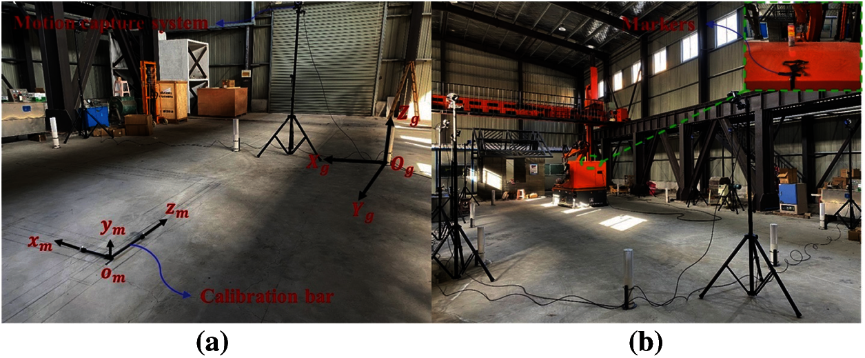
Figure 11: Preparation for the experimental test. (a) Calibration test (b) Experimental evaluation
4.2 Localization of Mobile 3D Printing Construction Robot in Different Stations
To complete the construction of the entire building in large-scale ongoing scene, the localization of mobile construction robot from 15 stations were tested. According to the process of Station 1 to Station 15 that shown in Fig. 12(Upper), a real mobile construction robot aided for 3D printing that integrated with functions of mapping, localization and planning for mobile robot was developed. Then, every station was designed to the corresponding architectural unit, and it was shown in the Fig. 12(Lower) by a real-time control software. In addition, to validate the effectiveness of optimized map, all artificial landmarks were set around the printed buildings and the mobile robot can move to the designated station without collision.
In addition, the printing-on-arrival strategy for printing large-scale buildings was adopted, which is to move to the designated station, and print the building in the designated station later. Assuming the ground of tested scene is flat, the planned route of mobile robot that from the Station S1 to Station S15 was conducted in Fig. 12(Lower). Correspondingly, the real-time localization results were displayed in our software. Finally, the localization results that based on optimized map were validated from Stations S1 to S15 for the mobile construction robot.
In order to verify the effectiveness of the optimized map to the localization of mobile 3D printing construction robot in 15 stations, the measured errors of the original and optimized artificial landmark map were compared. Also, the localization performances for mobile 3D printing construction robot that based on the original and optimized artificial landmark map were analyzed in detail.
5.1 Comparation Errors of the Original and Optimized Artificial Landmark Map
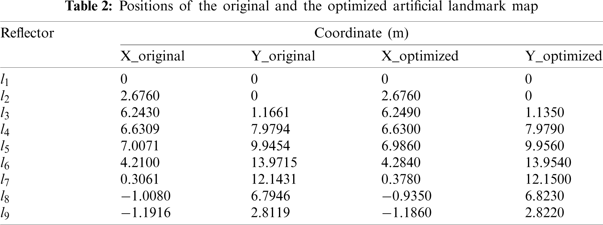
To reduce the uncertainty of the artificial landmark map, the nonlinear graph optimization method that proposed was adopted to the real robot. As a result, the coordinate values of artificial landmarks
As shown in Table 2, the differences of positions between the original and the optimized artificial landmark map were calculated by function (24), and the comparative results of errors are shown in Fig. 13.
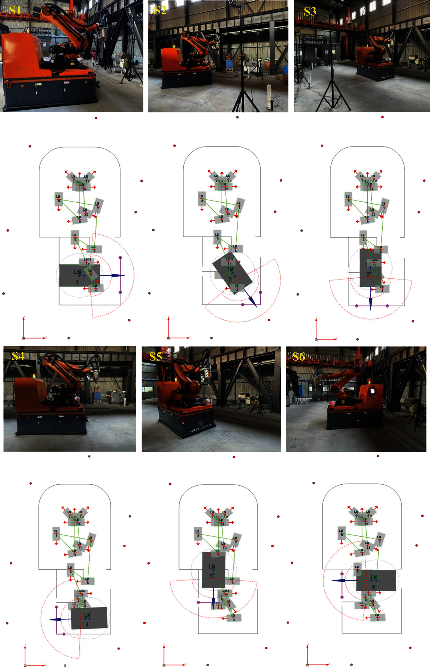
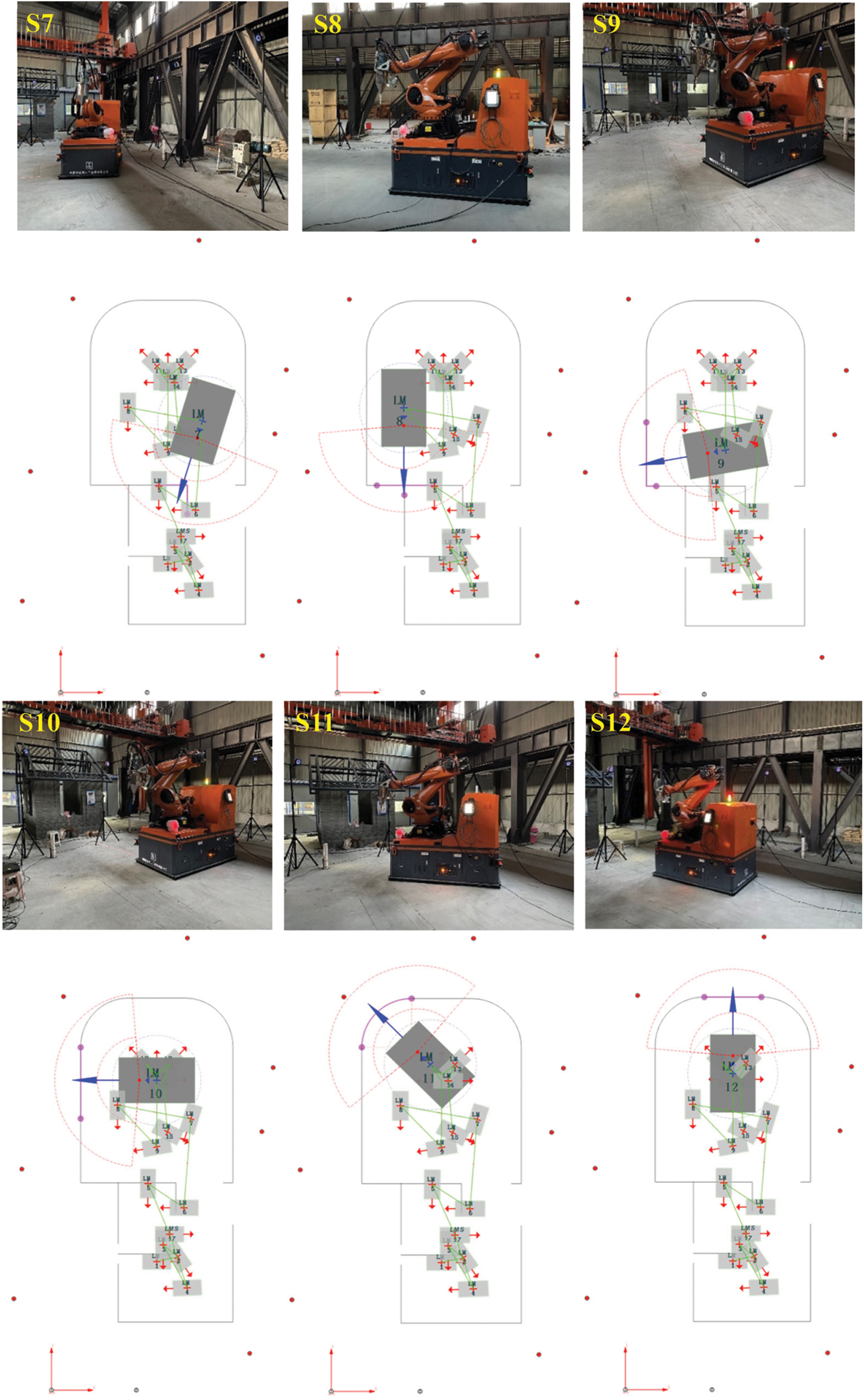
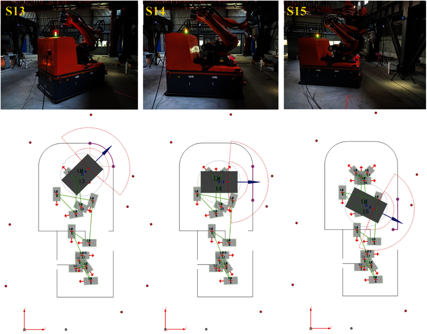
Figure 12: Flowchart of real-time localization for mobile 3D printing construction robot from S1 to S15. (Upper) Localization for robot body in indoor scene; (Lower) Visualization of software for localization based on robot model
According to the Fig. 13, the artificial landmarks were measured repeatedly, and the average errors of them were calculated. In Fig. 13a, the maximum average error on the x-axis was the reflector
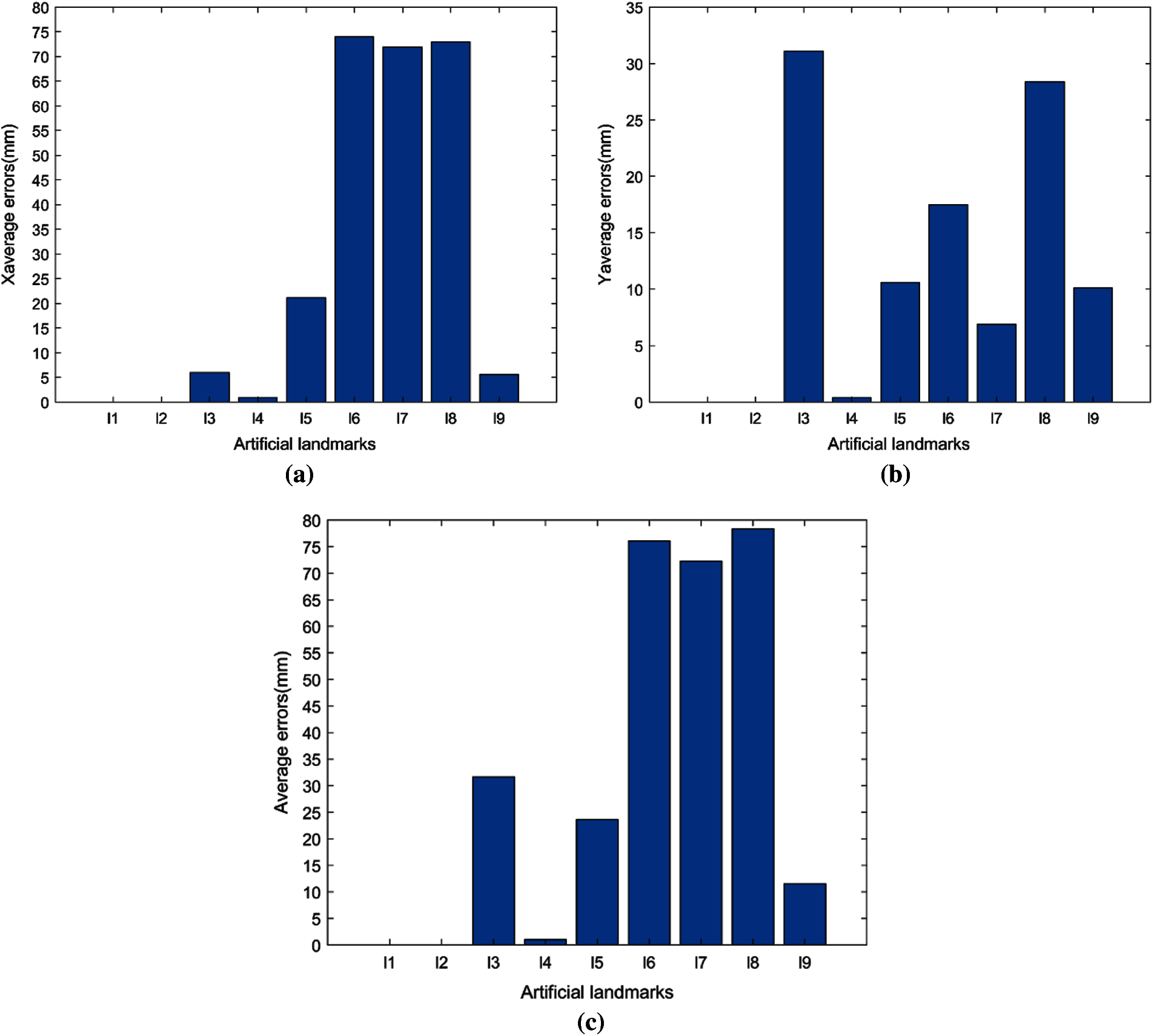
Figure 13: Average errors of the measured artificial landmarks. (a) Average errors in x-axis (b) Average errors in y-axis (c) Average errors in total
In addition, the coordinate values of all artificial landmark map were calculated, and the results of the original and optimized map were compared. The overall and partial enlarged map were visually displayed from the top view in Figs. 14a and 14b, which showed the differences between original centres and optimized centres.
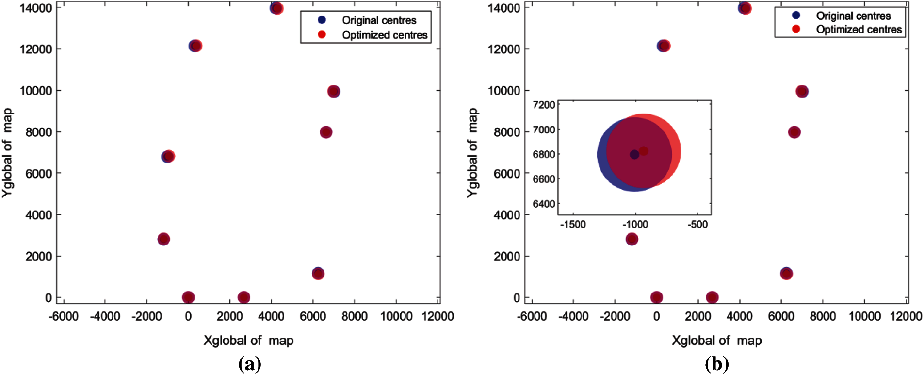
Figure 14: Visualization of the artificial landmark map between the original and optimized. (a) Top view of overall map (b) Top view of partial enlarged map
5.2 Localization Results of Mobile Robot in 15 Stations
For achieving the printing of large-scale buildings, the buildings are classified to 15 parts, and each part was printed in the designated station. Then, the poses of the markers that set upon the mobile robot were obtained by 3D motion capture system, and they were regarded as the ground truths of localization for mobile robot. Lastly, the localization results of mobile robot in 15 stations were measured.
In addition, to compare the localization errors between the measured values and the ground truths, the coordinate transformation of mobile robot in global coordinate system was established. It was represented as
where the coordinate parameter
According to the Table 3, the localization results of the mobile robot that based the original and optimized map from the 15 stations were analyzed. In addition, the measured results were compared and shown in the Fig. 15. The coordinate values in x-axis and y-axis that based on the optimized map (red) were closer to the truths (green) than the original (blue) as a whole in Figs. 15a and 15b.
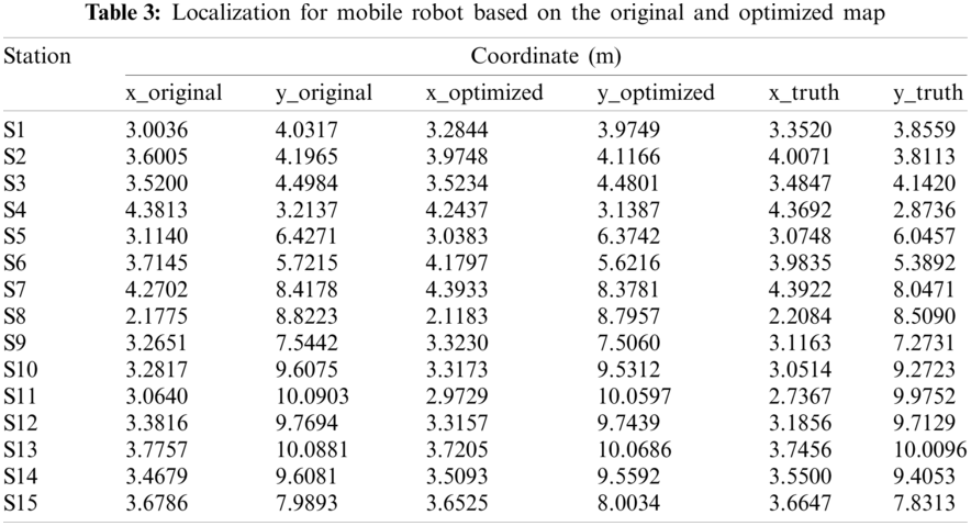
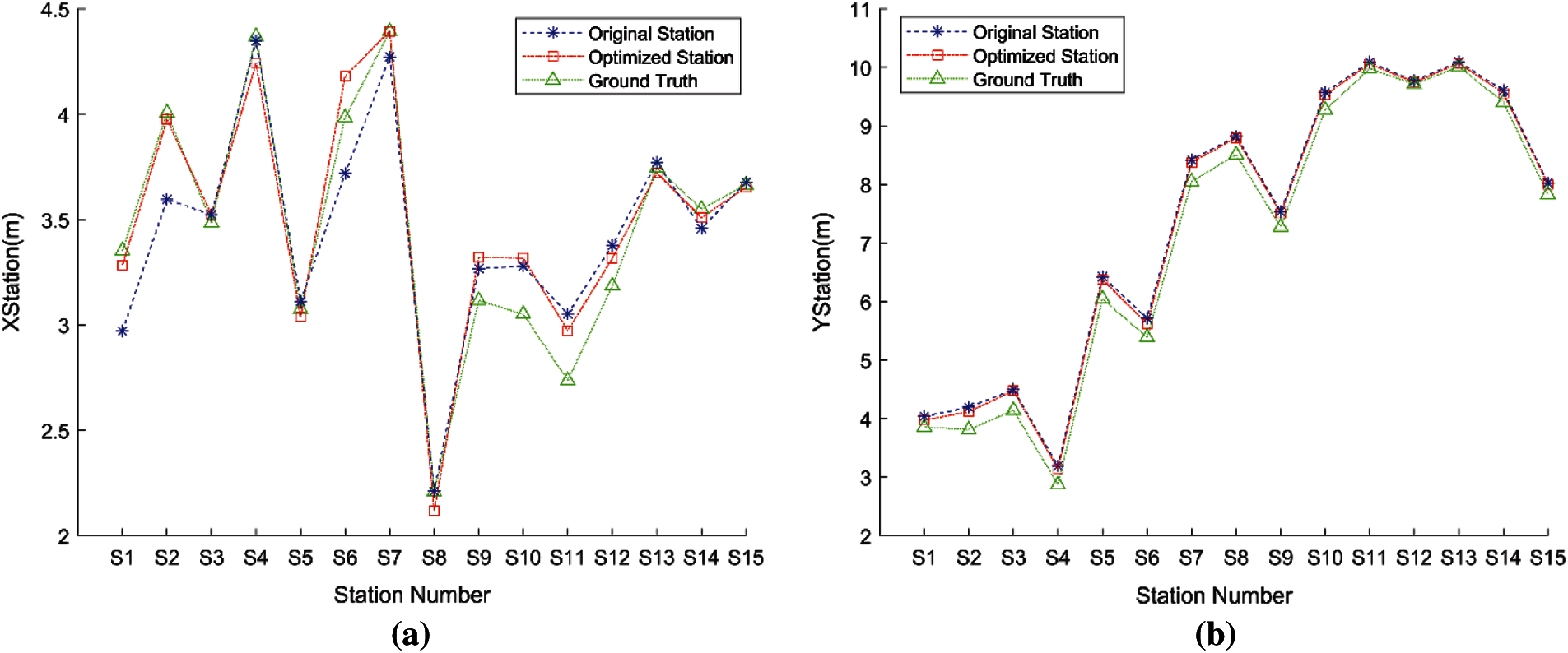
Figure 15: Localization comparation of mobile robot from 15 stations. (a) Coordinate results of x-axis (b) Coordinate results of y-axis
Meanwhile, the relative distance of two adjacent stations for mobile 3D printing construction robot were analyzed. As shown in Figs. 16a and 16b, the measured results that based on the original and optimized artificial landmark map were compared to the truth, and the relative errors of them were denoted as Original-Truth and Optimization-Truth. Through the comparative analysis from Figs. 16c and 16d, the relative errors of localization that based on the optimized map between two adjacent stations were reduced, which showed a better stability to a certain extent.
Figure 16: Comparations to relative localization for mobile robot from the adjacent stations. (a) Relative distances of Stations S1 to S8 (b) Relative distances of Stations S8 to S15 (c) Relative errors between two adjacent stations from S1 to S8 (d) Relative errors between two adjacent stations from S8 to S15
Further analysis of absolute localization errors for mobile robot were introduced in Fig. 17. On the whole, the localization accuracies of mobile robot were improved by the optimized map. Fig. 17a has shown the absolute localization errors of the x-axis based on the original and optimized artificial landmark map from Station S1 to Station S15. As a result, the minimum error denoted by red* were up to 1.1 mm in Station S7. However, the localization accuracies in Stations S4, S8, S9, S10 that based on the optimized map were not better than that of the original map. Meanwhile, Fig. 17b has shown that the localization results in y-axis based on the optimized artificial landmark map were better than that of the original map. The minimum absolute localization error that from the Station S12 was 31 mm. Fig. 17c has revealed that the total absolute localization errors from Station S1 to Station S15, and the localization accuracies of total for mobile robot were improved. Finally, the average localization errors based on the optimized map were reduced by about 21% compared to the original from all stations, which demonstrated a higher performance.
Figure 17: Comparison of absolute localization errors based on the original and optimized map. (a) Errors in x-axis (b) Errors in y-axis (c) Errors in total
In addition, the simulation of 3D printing buildings based on the mobile robot is depicted by the Unity software, and the construction process of the building is also visualized in Fig. 18. As shown in Fig. 18, the straight building unit that printed in a certain station by the robot is demonstrated. Fig. 18a represents the ConRob 3D simulation for 3D printing buildings, while Fig. 18b displays the virtual printing of the straight building unit by the manipulator. When the ConRob 3D simulation is over, the real mobile robot that on site for printing the building unit will work. The advantages of the designed workflow can be summarized as the following aspects: (1) The ConRob 3D simulation can effectively avoid the collision of the robot and printed buildings, the collision of robot’s joints and the printing head. (2) It can also mirror the process of printing buildings for a real robot, which provides a more intuitive demo in advance. (3) It greatly enhances the efficiency of printing buildings in a real robot, and extends the life of the robot.
Figure 18: Demonstration diagram of the robotics aided for printing the straight building unit in a certain station. (a) ConRob 3D simulation for printing buildings of the software (b) Virtual printing of the straight building unit by the mobile robot
To overcome the insufficient localization of mobile robot in featureless scene, an artificial landmark map is built in advance. Then, affected by the uncertainty of mapping, an accurate map is further constructed by a novel non-linear graph optimization method based on graphs. As a result, the localization performance of the mobile robot is improved, which effectively promotes the automation of architecture construction. This notion allowed us to improve the localization accuracy of the mobile robot by incorporating the reflectors attached with the high-reflective film for a large-scale ongoing scene. Experiments were performed in the large-scale indoor environment that surrounded by the building plan, which demonstrated a better localization of the mobile robot based on the optimized artificial landmark map. In addition, the main advantage of the proposed method was practical and efficient to the feature map and localization, which laid a better performance for the work of navigation and planning. In our future work, two aspects will be conducted gradually. The first work is to complete the real concrete printing based on the mobile robot on site. The mixer and pump equipment are integrated with the mobile robot, and the concrete architectural unit will be printed in sequence with collision-free. Another work is to develop the SLAM technology that is suitable for the artificial landmark map in large-scale ongoing scene, which is used to further improve the autonomous mobility of robotics and the degree of automated construction.
Acknowledgement: The authors would like to acknowledge National Natural Science Foundation of China (Nos. U1913603, 61803251, 51775322), National Key Research and Development Program of China (No. 2019YFB1310003) and Shanghai Robot Functional Platform for funding and support to this research.
Funding Statement: This research was supported by National Natural Science Foundation of China (Nos. U1913603, 61803251, 51775322), and National Key Research and Development Program of China (No. 2019YFB1310003).
Conflicts of Interest: The authors declare that they have no conflicts of interest to report regarding the present study.
1. Khoshnevis, B. (2004). Automated construction by contour crafting-related robotics and information technologies. Automation in Construction, 13(1), 5–19. DOI 10.1016/j.autcon.2003.08.012. [Google Scholar] [CrossRef]
2. Lim, S., Le, T., Webster, J., Buswell, R., Thorpe, T. (2009). Fabricating construction components using layer manufacturing technology. Global Innovation in Construction Conference, pp. 512–520. Loughborough, UK. [Google Scholar]
3. Le, T. T., Austin, S. A., Lim, S., Buswell, R. A., Law, R. et al. (2012). Hardened properties of high-performance printing concrete. Cement and Concrete Research, 42(3), 558–566. DOI 10.1016/j.cemconres.2011.12.003. [Google Scholar] [CrossRef]
4. Lim, S., Buswell, R. A., Le, T. T., Austin, S. A., Gibb, A. G. et al. (2012). Developments in construction-scale additive manufacturing processes. Automation in Construction, 21(1), 262–268. DOI 10.1016/j.autcon.2011.06.010. [Google Scholar] [CrossRef]
5. Barnett, E., Gosselin, C. (2015). Large-scale 3D printing with a cable-suspended robot. Additive Manufacturing, 7(10), 27–44. DOI 10.1016/j.addma.2015.05.001. [Google Scholar] [CrossRef]
6. Izard, J. B., Dubor, A., Hervé, P. E., Cabay, E., Culla, D. et al. (2017). Large-scale 3D printing with cable-driven parallel robots. Construction Robotics, 1(1), 1–8. DOI 10.1007/s41693-017-0008-0. [Google Scholar] [CrossRef]
7. Tho, T. P., Thinh, N. T. (2021). Using a cable-driven parallel robot with applications in 3D concrete printing. Applied Sciences, 11(2), 563. DOI 10.3390/app11020563. [Google Scholar] [CrossRef]
8. Carabin, G., Scalera, L., Wongratanaphisan, T., Vidonia, R. (2021). An energy-efficient approach for 3D printing with a linear delta robot equipped with optimal springs. Robotics and Computer-Integrated Manufacturing, 67(2), 102045. DOI 10.1016/j.rcim.2020.102045. [Google Scholar] [CrossRef]
9. Mechtcherine, V., Nerella, V. N., Will, F., Näther, M., Otto, J. et al. (2019). Large-scale digital concrete construction-CONPrint3D concept for on-site, monolithic 3D-printing. Automation in Construction, 107(11), 1–16. DOI 10.1016/j.autcon.2019.102933. [Google Scholar] [CrossRef]
10. Sustarevas, J., Butters, D., Hammid, M., Dwyer, G., Stuart-Smith, R. et al. (2018). MAP-A mobile agile printer robot for on-site construction. IEEE/RSJ International Conference on Intelligent Robots and Systems, pp. 2441–2448. Madrid, Spain. [Google Scholar]
11. Sustarevas, J., Benjamin Tan, K. X., Gerber, D., Stuart-Smith, R., Pawar, V. M. (2019). YouWasps: Towards autonomous multi-robot mobile deposition for construction. IEEE/RSJ International Conference on Intelligent Robots and Systems, pp. 2320–2327. Macau, China. DOI 10.1109/IROS40897.2019.8967766. [Google Scholar] [CrossRef]
12. Subrin, K., Bressac, T., Garnier, S., Ambiehl, A., Paquet, E. et al. (2018). Improvement of the mobile robot location dedicated for habitable house construction by 3D printing. IFAC-PapersOnLine, 51(11), 716–721. DOI 10.1016/j.ifacol.2018.08.403. [Google Scholar] [CrossRef]
13. Zhang, X., Li, M., Lim, J. H., Weng, Y., Tay, Y. W. D. et al. (2018). Large-scale 3D printing by a team of mobile robots. Automation in Construction, 95(3), 98–106. DOI 10.1016/j.autcon.2018.08.004. [Google Scholar] [CrossRef]
14. Tiryaki, M. E., Zhang, X., Pham, Q. C. (2019). Printing-while-moving: A new paradigm for large-scale robotic 3D Printing. IEEE/RSJ International Conference on Intelligent Robots and Systems, pp. 2286–2291. Macau, China. DOI 10.1109/IROS40897.2019. [Google Scholar] [CrossRef]
15. Leonard, J. J., Durrant-Whyte, H. F. (1991). Mobile robot localization by tracking geometric beacons. IEEE Transactions on Robotics and Automation, 7(3), 376–382. DOI 10.1109/70.88147. [Google Scholar] [CrossRef]
16. Burgard, W., Fox, D., Hennig, D., Schmidt, T. (1996). Estimating the absolute position of a mobile robot using position probability grids. Proceedings of the National Conference on Artificial Intelligence, pp. 896–901. Portland, Oregon. [Google Scholar]
17. Howard, A., Mataric, M. J., Sukhatme, G. (2001). Relaxation on a mesh: A formalism for generalized localization. Proceedings 2001 IEEE/RSJ International Conference on Intelligent Robots and Systems, vol. 2, pp. 1055–1060. Maui, HI, USA. [Google Scholar]
18. Rafflin, C., Fournier, A. (1995). Trajectory learning for a friendly interactive robot for service tasks. IEEE International Conference on Systems, pp. 3706–3711. Vancouver BC, Canada. [Google Scholar]
19. Wallgrün, IJO (2010). Robot mapping. Berlin, Heidelberg: Springer. [Google Scholar]
20. Simmons, R., Koenig, S. (1995). Probabilistic robot navigation in partially observable environments. 1995 Proceedings of the 14th International Joint Conference on Artificial Intelligence, pp. 1080–1087. San Francisco, CA, USA. [Google Scholar]
21. Huang, Z., Zhu, J., Yang, L., Xue, B., Wu, J. et al. (2015). Accurate 3-D position and orientation method for indoor mobile robot navigation based on photoelectric scanning. IEEE Transactions on Instrumentation and Measurement, 64(9), 2518–2529. DOI 10.1109/TIM.2015.2415031. [Google Scholar] [CrossRef]
22. Easton, A., Cameron, S. (2006). A gaussian error model for triangulation-based pose estimation using noisy landmarks. IEEE Conference on Robotics, Automation and Mechatronics, pp. 1–6. Bangkok, Thailand. DOI 10.1109/RAMECH.2006.252663. [Google Scholar] [CrossRef]
23. Lerner, R., Rivlin, E., Shimshoni, I. (2007). Landmark Selection for task-oriented navigation. IEEE Transactions on Robotics, 23(3), 494–505. DOI 10.1109/TRO.2007.895070. [Google Scholar] [CrossRef]
24. Sutherland, K. T., Thompson, W. B. (1993). Inexact navigation. IEEE International Conference on Robotics and Automation, pp. 1–7. Atlanta, GA, USA. [Google Scholar]
25. Shoval, S., Sinriech, D. (2001). Analysis of landmark configuration for absolute positioning of autonomous vehicles. Journal of Manufacturing Systems, 20(1), 44–54. DOI 10.1016/S0278-6125(01)80019-4. [Google Scholar] [CrossRef]
26. Meyerdelius, D., Beinhofer, M., Kleiner, A. Burgard, W. (2011). Using artificial landmarks to reduce the ambiguity in the environment of a mobile robot. IEEE International Conference on Robotics and Automation, pp. 5173–5178. Shanghai, China. [Google Scholar]
27. Salas, J., Gordillo, J. L. (1998). Placing artificial visual landmarks in a mobile robot workspace. In: 1998 progress in artificial intelligence. Berlin, Heidelberg: Springer. [Google Scholar]
28. Sala, P. L., Sim, R., Shokoufandeh, A., Dickinson, S. J. (2006). Landmark selection for vision-based navigation. IEEE Transactions on Robotics, 22(2), 334–349. DOI 10.1109/TRO.2005.861480. [Google Scholar] [CrossRef]
29. Xu, Z., Yu, Z., Liu, H. (2017). Design and recognition of artificial landmarks for reliable indoor self-localization of mobile robots. International Journal of Advanced Robotic Systems, 14(1), 1–13. DOI 10.1177/1729881417693489. [Google Scholar] [CrossRef]
30. Shamsfakhr, F., Bigham, B. S., Mohammadi, A. (2019). Indoor mobile robot localization in dynamic and cluttered environments using artificial landmarks. Engineering Computations, 36(2), 400–419. DOI 10.1108/EC-03-2018-0151. [Google Scholar] [CrossRef]
31. Naseer, T., Suger, B., Ruhnke, M. Burgard, W. (2016). Vision-based Markov localization for long-term autonomy. Robotics and Autonomous Systems, 89(9), 147–157. DOI 10.1016/j.robot.2016.11.008. [Google Scholar] [CrossRef]
32. Phang, D. R., Lee, W., Matsuhira, N., Michail, P. (2020). Enhanced mobile robot localization with lidar and IMU sensor. IEEE International Meeting for Future of Electron Devices, Kansai (IMFEDK), pp. 71–72. San Francisco, CA, USA. [Google Scholar]
33. Thrun, S. (1998). Finding landmarks for mobile robot navigation. 1998 IEEE International Conference on Robotics and Automation, pp. 958–963. Leuven, Belgium. [Google Scholar]
34. Li, H., Mao, Y., You, W., Ye, B., Zhou, X. (2020). A neural network approach to indoor mobile robot localization. 19th International Symposium on Distributed Computing and Applications for Business Engineering and Science, pp. 66–69. Xuzhou, China. [Google Scholar]
35. Xu, Y., Shmaliy, Y. S., Ma, W., Jiang, X., Shen, T. et al. (2021). Improving tightly LiDAR/compass/encoder-integrated mobile robot localization with uncertain sampling period utilizing EFIR filter. Mobile Networks and Applications, 26(5), 1–9. DOI 10.1007/s11036-020-01680-7 [Google Scholar] [CrossRef]
36. Chen, Y., Hafez, O. A., Pervan, B., Spenko, M. (2021). Landmark augmentation for mobile robot localization safety. IEEE Robotics and Automation Letters, 6(1), 119–126. DOI 10.1109/LRA.2020.3032067. [Google Scholar] [CrossRef]
37. Cadena, C., Carlone, L., Carrillo, H., Latif, Y., Scaramuzza, D. et al. (2016). Past, present, and future of simultaneous localization and mapping: Toward the robust-perception age. IEEE Transactions on Robotics, 32(6), 1309–1332. DOI 10.1109/TRO.2016.2624754. [Google Scholar] [CrossRef]
38. Jia, Y., Yan, X., Xu, Y. (2019). A survey of simultaneous localization and mapping for robot. IEEE 4th Advanced Information Technology, Electronic and Automation Control Conference, pp. 857–861. DOI 10.1109/IAEAC47372.2019.8997820. [Google Scholar] [CrossRef]
39. Beinhofer, M., Kretzschmar, H., Burgard, W. (2013). Deploying artificial landmarks to foster data association in simultaneous localization and mapping. IEEE International Conference on Robotics and Automation, pp. 5235–5240. Karlsruhe, Germany. [Google Scholar]
40. Strasdat, H., Stachniss, C., Burgard, W. (2009). Which landmark is useful? Learning selection policies for navigation in unknown environments. IEEE International Conference on Robotics and Automation, pp. 1410–1415. Kobe, Japan. [Google Scholar]
41. Zheng, S., Xie, L. H., Adams, M. D. (2005). Entropy based feature selection scheme for real time simultaneous localization and map building. IEEE/RSJ International Conference on Intelligent Robots and Systems, pp. 1175–1180. Edmonton, AB, Canada. DOI 10.1109/IROS.2005.1545054. [Google Scholar] [CrossRef]
42. Lauer, M., Lange, S., Riedmiller, M. (2006). Calculating the perfect match: An efficient and accurate approach for robot self-localization. In: RoboCup 2005, Robot soccer world cup IX lecture notes in computer science. Springer, Berlin, Heidelberg. DOI 10.1007/11780519_13. [Google Scholar] [CrossRef]
43. Sobreira, H., Costa, C. M., Sousa, I., Rocha, L., Lima, J. et al. (2019). Map-matching algorithms for robot self-localization: A comparison between perfect match, iterative closest point and normal distributions transform. Journal of Intelligent & Robotic Systems, 93(3–4), 533–546. DOI 10.1007/s10846-017-0765-5. [Google Scholar] [CrossRef]
44. Garrote, L., Torres, M., Barros, T., Perdiz, J., Premebida, C. et al. (2019). Mobile robot localization with reinforcement learning map update decision aided by an absolute indoor positioning system. IEEE/RSJ International Conference on Intelligent Robots and Systems, pp. 1620–1626. Macau. [Google Scholar]
45. Boniardi, F., Caselitz, T., Kümmerle, R., Burgard, W. (2019). A pose graph-based localization system for long-term navigation in CAD floor plans. Robotics and Autonomous Systems, 112(3), 84–97. DOI 10.1016/j.robot.2018.11.003. [Google Scholar] [CrossRef]
46. Boniardi, F., Caselitz, T., Kümmerle, R., Burgard, W. (2017). Robust LiDAR-based localization in architectural floor plans. IEEE/RSJ International Conference on Intelligent Robots and Systems, pp. 3318–3324.Vancouver, BC, Canada. [Google Scholar]
47. Gawel, A., Blum, H., Pankert, J., Krämer, K., Bartolomei, L. et al. (2019). A fully-integrated sensing and control system for high-accuracy mobile robotic building construction. IEEE/RSJ International Conference on Intelligent Robots and Systems, pp. 2300–2307. Macau. [Google Scholar]
48. Jenny, S. E., Blum, H., Gawel, A., Siegwart, R., Gramazio, F. et al. (2020). Online synchronization of building model for on-site mobile robotic construction. 37th International Symposium on Automation and Robotics in Construction, pp. 1508–1514. Aarhus, Denmark. [Google Scholar]
49. Xu, Z., Guo, S., Song, T., Zeng, L. (2020). Robust localization of the mobile robot driven by lidar measurement and matching for ongoing scene. Applied Sciences, 10(18), 6152. DOI 10.3390/app10186152. [Google Scholar] [CrossRef]
50. Schwertfeger, S., Jacoff, A., Scrapper, C., Pellenz, J., Kleiner, A. (2010). Evaluation of maps using fixed shapes: The fiducial map metric. Proceedings of the 10th Performance Metrics for Intelligent Systems Workshop, pp. 339–346. New York, USA. [Google Scholar]
51. Li, H., Zhang, Q., Zhao, D. (2017). Comparison of methods to efficient graph slam under general optimization framework. 32nd Youth Academic Annual Conference of Chinese Association of Automation, pp. 321–326. Hefei, China. [Google Scholar]
52. Wulf, O., Nuchter, A., Hertzberg, J., Wagner, B. (2007). Ground truth evaluation of large urban 6D SLAM. IEEE/RSJ International Conference on Intelligent Robots and Systems, pp. 650–657. San Diego, CA, USA. [Google Scholar]
53. Kümmerle, R., Steder, B., Dornhege, C., Ruhnk, M., Grisetti, G. et al. (2009). On measuring the accuracy of SLAM algorithms. Autonomous Robots, 27(4), 387–407. DOI 10.1007/s10514-009-9155-6. [Google Scholar] [CrossRef]
54. Madsen, K., Nielsen, H. B., Tingleff, O. (2004). Methods for non-linear least squares problems, 2nd edition. Denmark: Informatic and Mathematical Modelling Technical University of Denmark. [Google Scholar]
55. Mao, J., Hu, X., Milford, M. (2018). An adaptive localization system for image storage and localization latency requirements. Robotics and Autonomous Systems, 107, 246–261. DOI 10.1016/j.robot.2018.06.007. [Google Scholar] [CrossRef]
56. Guo, S., Yan, Z. X., Song, T., Xu, Z., Zeng, L. D. (2019). Improvement of localization with artificial landmark for mobile manipulator. International Journal of Advanced Robotic Systems, 16(4), 172988141986298. DOI 10.1177/1729881419862985. [Google Scholar] [CrossRef]
 | This work is licensed under a Creative Commons Attribution 4.0 International License, which permits unrestricted use, distribution, and reproduction in any medium, provided the original work is properly cited. |