DOI:10.32604/csse.2021.015528
| Computer Systems Science & Engineering DOI:10.32604/csse.2021.015528 | |
| Article |
Comparative Design and Study of A 60 GHz Antenna for Body-Centric Wireless Communications
1Department of Electrical and Computer Engineering, North South University, Bashundhara, Dhaka-1229, Bangladesh
2Department of Computer Science, College of Computers and Information Technology, Taif University, P. O. Box 11099, Taif 21944, Saudi Arabia
*Corresponding Author: Mohammad Monirujjaman Khan. Email: monirujjaman.khan@northsouth.edu
Received: 25 November 2020; Accepted: 24 December 2020
Abstract: In this paper performance of three different designs of a 60 GHz high gain antenna for body-centric communication has been evaluated. The basic structure of the antenna is a slotted patch consisting of a rectangular ring radiator with passive radiators inside. The variation of the design was done by changing the shape of these passive radiators. For free space performance, two types of excitations were used—waveguide port and a coaxial probe. The coaxial probe significantly improved both the bandwidth and radiation efficiency. The center frequency of all the designs was close to 60 GHz with a bandwidth of more than 5 GHz. These designs achieved a maximum gain of 8.47 dB, 10 dB, and 9.73 dB while the radiation efficiency was around 94%. For body-centric applications, these antennas were simulated at two different distances from a human torso phantom using a coaxial probe. The torso phantom was modeled by taking three layers of the human body—skin, fat, and muscle. Millimeter waves have low penetration depth in the human body as a result antenna performance is less affected. A negligible shift of return loss curves was observed. Radiation efficiencies dropped at the closest distance to the phantom and at the furthest distance, the efficiencies increased to free space values. On the three layers human body phantom, all three different antenna designs show directive radiation patterns towards off the body. All three designs exhibited similar results in terms of center frequency and efficiency but varied slightly by either having better bandwidth or maximum gain.
Keywords: Body-centric communication; coaxial probe; high gain; millimeter-wave; 60 GHz; on-body; patch; compact antenna; antenna performance
Millimeter-Wave (mm-wave) spectrum ranges from 30 to 300 GHz having a wavelength range of 10 mm to 1 mm. The 60 GHz band from 57 to 66 GHz is unlicensed and relatively less congested around the world. In 2001, the Federal Communications Commission (FCC) allocated 57–64 GHz for unlicensed use and so gathered lots of interest of many researchers [1]. Due to very short wavelength and high bandwidth, communication at 60 GHz band is suitable for high data rate (Gbps) short-range applications like file transfer between multiple devices, high definition video streaming, and many more. Millimeter waves have high atmospheric absorption and high propagation attenuation and are also vulnerable to blockage by everyday obstacles like a brick wall, human bodies, etc. As a result, 60 GHz communication will work best in confined obstacle-free areas like medical wards, libraries, conference rooms, etc. [1,2].
Antennas designed for mm-wave are very small in size and are very directional [1]. These antennas can be used for body-centric devices like medical sensors which may consist of a heart-rate monitor, blood pressure, Electrocardiogram (ECG), and many more [3]. Body-centric wireless communications (BCWC) is an emerging technology which has great potential for applications in healthcare for patient monitoring. The concept of BCWC includes Wireless Body Area Networks (WBANs), Wireless Personal Area Networks (WPANs) and Wireless Body Sensor Networks (WBSNs). Body Area Network (BAN) is a small scale network around a human body. Wireless body area networks (WBANs) are communication networks of sensor nodes placed on, inside, or around the human body. There are many sensors uniformly distributed around the body to monitor the patient’s health, and each sensor gathers data and sends it to the Master Node (MN). The MN then directs the data to the monitor node, which either analyses it, or forwards it over the internet to, the hospital or doctors. Wireless body sensor network (WBSN) technologies are one of the most powerful technologies which consist of a group of low-power and lightweight devices with a transceiver which are used to monitor the vital signs of the human body [4–8]. BAN contains three modes of communication: off- body, on-body and in-body. When an off-body device communicates with a device placed on-body, it is known as off-body communication. Communication between sensors within close proximity of the body is on-body communication and communication between an implant with an outside sensor network is called in-body communication [9].
Antennas are the important component for wearable devices in body-centric wireless communications and they play a vital role in optimizing the radio system performance. Human body is an unfriendly environment for on-body communications. The performance of antennas for BCWC can be degraded by the presence of the lossy human body tissues. Due to the capacitive property of the human body, antenna radiation efficiency, input impedance, radiation pattern, and the resonant frequency are greatly affected [9,10]. So while designing an antenna for BAN, it is very important to study the antenna’s performance for body-centric scenarios using an appropriate approximation of the human body for power efficient and reliable on-body communications [9]. A human body can be modeled by three layers consisting of skin, fat, and muscle. At 60 GHz penetration depth of the mm-wave is very low. The skin has a loss tangent of 1.37 with an average penetration depth of 0.48 mm, fat has a loss tangent of 0.27 with an average penetration of depth of 3.37 mm and lastly, the muscle has an average penetration depth of 0.41 mm with a loss tangent of 0.0012 [11].
In [12], Al-Alem and A. Kishk designed a very low profile via-less planar Microstrip monopole antenna based on a very thin layer of a substrate. The main antenna structure is placed in between two copper reflectors and is fed by a 50 Ω Microstrip line. The antenna achieved a boresight gain of 11 dB and a bandwidth of 7 GHz (57–64 GHz). Chen et al. designed three 60 GHz antennas based on a PCB substrate to keep the fabrication cost low [13]. In this paper, the authors first proposed an antipodal slot based antenna on a very thin layer PCB substrate. For the frequency range of 57–67 GHz, the antenna achieved a very high gain of 15.6–17.2 dBi. In the same paper, the authors also presented a fan-like antenna consisting of blade-like arms on opposite sides of the PCB substrate to form two antipodal tapered radiators. Over a frequency of 57–64 GHz, this design achieved a gain of 1.6–6.4 dBi. Finally, the authors proposed a substrate integrated waveguide cavity-backed wide slot array antenna which resulted in 10–12 dBi gain over an operating bandwidth of 11.6% [13]. To achieve high gain, Vettikalladi et al. proposed two antenna designs based on dielectric superstrate having a relative permittivity of 7.5 [14]. In this paper, the authors first designed an aperture coupled patch antenna where the superstrate layer is added above 0.5  height from the ground. The antenna is fed with a 50 Ω microstrip line and achieved a simulated result of 14.9 dBi from 58.7 to 62.7 GHz with an efficiency of 76%. In the same paper, the authors proposed a Microstrip fed stacked superstrate which contains a parasitic patch placed above 0.35 mm from the main patch. This design also has a high gain of 13.6 dBi with 84% efficiency [14]. Li and Luk proposed a magneto-electric dipole antenna in their paper. The antenna consists of two planar dipoles and a shorted patch which gained a wide bandwidth of about 50% with a stable gain of 8 dBi [15]. Al-Alem and Kishk designed an antenna which utilizes open-end Microstrip line fringing fields in another of their papers. The antenna has a realized gain of 11.5 dBi and a bandwidth of 2.2 GHz [16]. To achieve a very high gain a spherical dielectric lens has been implemented in [17]. The spherical dielectric lens of the proposed Microstrip antenna is fed by a slot-fed circular patch. A cavity is created around a thick substrate to hold the lens in place. Dielectric lenses increase gain by focusing radiation energy and this design achieved a very high normalized gain of 21.7 dB.
There are quite a few 60 GHz antennas that have been designed for on-body wearable devices. One such design was presented in [18] where the antenna is designed for wearable smart glasses. The basic structure contains a patch antenna array with feed lines, parasitic elements, and a ground. For the wearable scenario, the antenna was simulated on a head phantom. The antenna showed wide radiation coverage for both simulated and fabricated designs with a return loss bandwidth of around 1 GHz. In [19] Puskely et al. designed a disc-like circular antenna from a substrate integrated waveguide horn antenna. For on-body simulation, a skin phantom of 2 mm thickness was created. The reflection coefficient observed for both free space and on-body was almost identical with a bandwidth of 8%. The antenna produced an omnidirectional radiation pattern in both free space and on-body setup. In free space maximum gain achieved by the antenna is 4.8 dBi while for on-body the gain varied from 1.1 to 8.8 dBi depending on the placement of the antenna from the phantom. Antenna arrays with three different feeding techniques have been presented in [20]. Depending on feeding techniques in free space and on phantom the antenna gain varied from 9.4 dBi to 10 dBi. In [21] a very low profile slotted patch antenna has achieved a gain of 10.6 dBi in free space, while in body phantom the gain was 12.1 dBi. In [22] 60-GHz textile antenna array for body-centric communications is presented. Millimeter-wave liquid crystal polymer based conformal antenna array for 5G applications has been demonstrated in [23]. In [24] planar millimeter-wave antenna on low-cost flexible PET substrate for 5G applications is presented.
From the literature review, it is evident that an mm-wave antenna has to be high gain, a low cost, and an uncomplicated structure. For the on-body scenario, the antenna should show a good radiation pattern without much degradation of antenna performance. For body-centric communications different authors have presented different design approaches for mm wave antennas. However, there is still not any breakthrough for the suitable antenna design for reliable mm wave body-centric communications. In this paper, low profile and novel 60 GHz high gain antenna design for body-centric wireless communications is proposed. The main objective of this paper is to compare and analyze the performance of a 60 GHz antenna with three different designs. The performance parameters of these three different antenna designs are analyzed both in free space and on the three layers human body model. In this paper three different designs of a 60 GHz antenna have been chosen to investigate and compare the performance parameters of the antenna in terms of center frequency, bandwidth, efficiency, gain and radiation pattern.
This paper is divided into five sections—Introduction, design, free space simulation, on-body simulation, and conclusion. In section 1 the concepts of mm-wave and body-centric communication have been introduced. We also discussed some available 60 GHz antennas for both free space and on-body application. Section 2 is a description of all three design forms of the proposed antenna. Section 3 contains free space performance evaluation of all three designs for both waveguide port excitation and coaxial probe feed. Section 4 is dedicated to on-body simulated results at two different positions from a torso phantom using only the coaxial probe. In the last section, a conclusion is drawn in terms of the radiation pattern, return loss, and efficiency.
Designing and simulation of the antenna are done using Computer Simulation Technology (CST). The basic structure of the three antenna designs consists of a ground plane, an air gap sandwiched in between two very thin layers of Flexible Printed Circuit Board (FPCB) substrate. FPCB is a flexible material with a dielectric constant of 2.7 and a loss tangent of 0.005 at 60 GHz [5,16]. The main radiator consists of a rectangular ring of 1 mm width inside which three more passive radiators are placed evenly at 0.15 mm apart. The ground at the bottom part of the antenna will help direct the radiation in upward direction. The ground and the radiators are of thickness 0.035 mm. The overall dimension of the antenna is 14 mm × 10.5 mm × 1.22 mm. The wavelength of the antenna at 60 GHz is 5 mm. The electrical sizes of the proposed antenna are 2.8 λ for width and 2.1 λ for length, respectively. This size has been considered for the antenna overall ground plane size. By varying the shape of the passive radiators while keeping the size of the ring the same, we have created three designs and named them as Design 1, Design 2, and Design 3. A Microstrip feed line of width 1.5 mm with a feed gap of 1 mm is created.
Design 1 consists of three rectangular passive blocks. Each block is of size 2.8 mm × 4.6 mm (Fig. 1a). In Design 2 and Design 3 the blocks are cut to form letter-shaped radiators. The shape of these passive radiators in Design 2 is “n S U” while in Design 3 it is “N S U” [Fig. 1b, 1c].
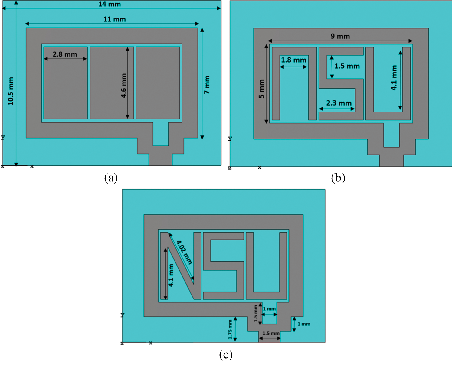
Figure 1: Top view of (a) Design 1 (b) Design 2 (c) Design 3
To form the letters “n”& “U” in Design 2 a rectangular portion of 1.8 mm × 4.1 mm was cut off from the left and the right passive blocks of Design 1. To form the “N” two identical triangles of sides 4.1 mm, 4.02 mm and 3.6 mm are cut from the left block of design 1. The letter “S” is formed by cutting two identical rectangles of 1.5 mm × 2.3 mm from the center block of design 1. Figs. 2a–2c show the top (left) and bottom (right) view of Design 1 with coaxial feed, Design 1 with waveguide excitation and coaxial feed, respectively.

Figure 2: (a) Top and bottom view of Design 1, (b) Design 1 with waveguide excitation and (c) Design with coaxial feed
A waveguide port and a coaxial probe were used as a source of excitation to find the optimum feed. A waveguide port of size 9.09 mm × 5.36 mm is placed as a source of excitation. The coaxial probe was placed over the feedline replacing the waveguide port as a source of excitation. The coaxial probe has an inner conductor of size 0.448 mm to match a 50 Ω line. The optimum position for placing the probe is 10.635 mm from the origin for Design 2 and 3. For Design 1 the optimum position is 10.56 mm from the origin.
3.1 Result Using Waveguide Port
Fig. 3 shows the return loss curve for all three designs with waveguide port excitation. For Design 1, the return loss at −10 dB ranges from 56.78 GHz to 61.76 GHz, which gives a bandwidth of 4.96 GHz. The center frequency is 59.58 GHz at a return loss of −14.56 dB. Design 2 at −10 dB return loss, frequency ranges from 57.21 GHz to 61.62 GHz, which is a bandwidth of 4.41 GHz. The center frequency is 59.48 GHz at a return loss of −28.29 dB. Design 3 has a center frequency of 59.50 GHz at a return loss of −32.66 dB. At −10 dB the bandwidth is 4.26 GHz, ranging from 57.37 GHz to 61.63 GHz. Tab. 1 shows the free space performance summary of waveguide port antennas for 3 different designs.

Figure 3: The return loss curves for all three designs with waveguide port excitation
Table 1: Free space performance summary of waveguide port antennas for 3 different designs
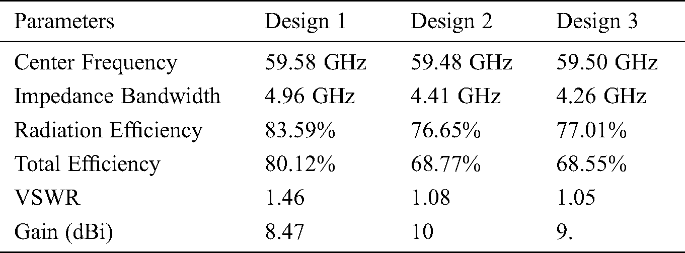
At their respective center frequencies Design 2 and 3 achieved similar linear radiation and total efficiency while Design 1 achieved better efficiency. Radiation efficiency for Design 1 is 83.59% while the total efficiency is 80.12%. Design 2 and 3 have achieved a radiation efficiency of 76.65%, 77.01%, and a total efficiency of 68.77%, 68.55% respectively.
Voltage Standing Wave Ratio (VSWR) for Design 1, 2, and 3 is 1.46, 1.08, and 1.05 respectively at their center frequencies. This shows that Design 2 and 3 are very well matched when compared to Design 1. Electromagnetic coupling causes current to flow along the passive radiators. The maximum surface current at 60 GHz is around 202 A/m, 213 A/m, and 215 A/m for Design 1, 2, and 3, respectively.
Design 1 achieved a maximum gain of 8.47 dB at 60 GHz. Figs. 4a and 4b show the radiation patterns in XZ, and YZ planes of the waveguide port antennas at 60 GHz for three different designs. The radiation pattern of the YZ plane has a main lobe of magnitude 7.94 dB at direction of 15 degrees. XZ plane has a main lobe magnitude of 3.96 dB at 326 degrees. At 60 GHz Design 2 has a maximum gain of 10 dB. The magnitude of the main lobe in YZ and XZ planes is 4.55 dB at 343 degrees and 9.78 dB at 321 degrees, respectively. For the same frequency, the magnitude of the main lobe of Design 3 in the YZ plane is 4.96 dB at 15 degrees while in the XZ plane the main lobe magnitude is 9.52 dB at 320 degrees. Design 3 achieved a maximum gain of 9.73 dB. From these values, it can be concluded that these antenna designs are very directional and they only radiate in certain directions.

Figure 4: Radiation patterns of waveguide port antennas at 60 GHz in (a) XZ, and (b) YZ plane
3.2 Results Using Coaxial Probe
The return loss curve indicates that the center frequencies of the three designs with coaxial feed have shifted to the right when compared to the waveguide port. An increase in bandwidth is also observed in all three designs. At −10 dB return loss of Design 1, frequency ranges from 57.38 GHz to 63.20 GHz with a center frequency of 60.02 GHz at −20.16 dB. Design 2 has a center frequency of 60.14 GHz at −22.72 dB. At −10 dB return loss, frequency ranges from 57.95 GHz to 63 GHz. For the same return loss of −10 dB, Design 3 has a bandwidth of 5.05 GHz (from 58.04 GHz to 63.09 GHz), with a center frequency of 60.08 GHz at −24.24 dB.
Use of the coaxial probe increased both radiation efficiency and total efficiency significantly for all the designs. Radiation efficiency increased to 94.48%, 94.25% and 94.70% while total efficiency increased to 93.50%, 93.19% and 94.03% for Design 1, 2 and 3 respectively (see Fig. 5). VSWR for Design 1 decreased to 1.22 but for Design 2 and 3 VSWR increased to 1.16 and 1.13 at their respective center frequencies. Surface current at 60 GHz increased to a maximum value of 305, 311, and 315 A/m for the three designs; see Figs. 6a–6c.

Figure 5: Radiation and total efficiency of coaxial feed Design 1, 2 & 3 in free space
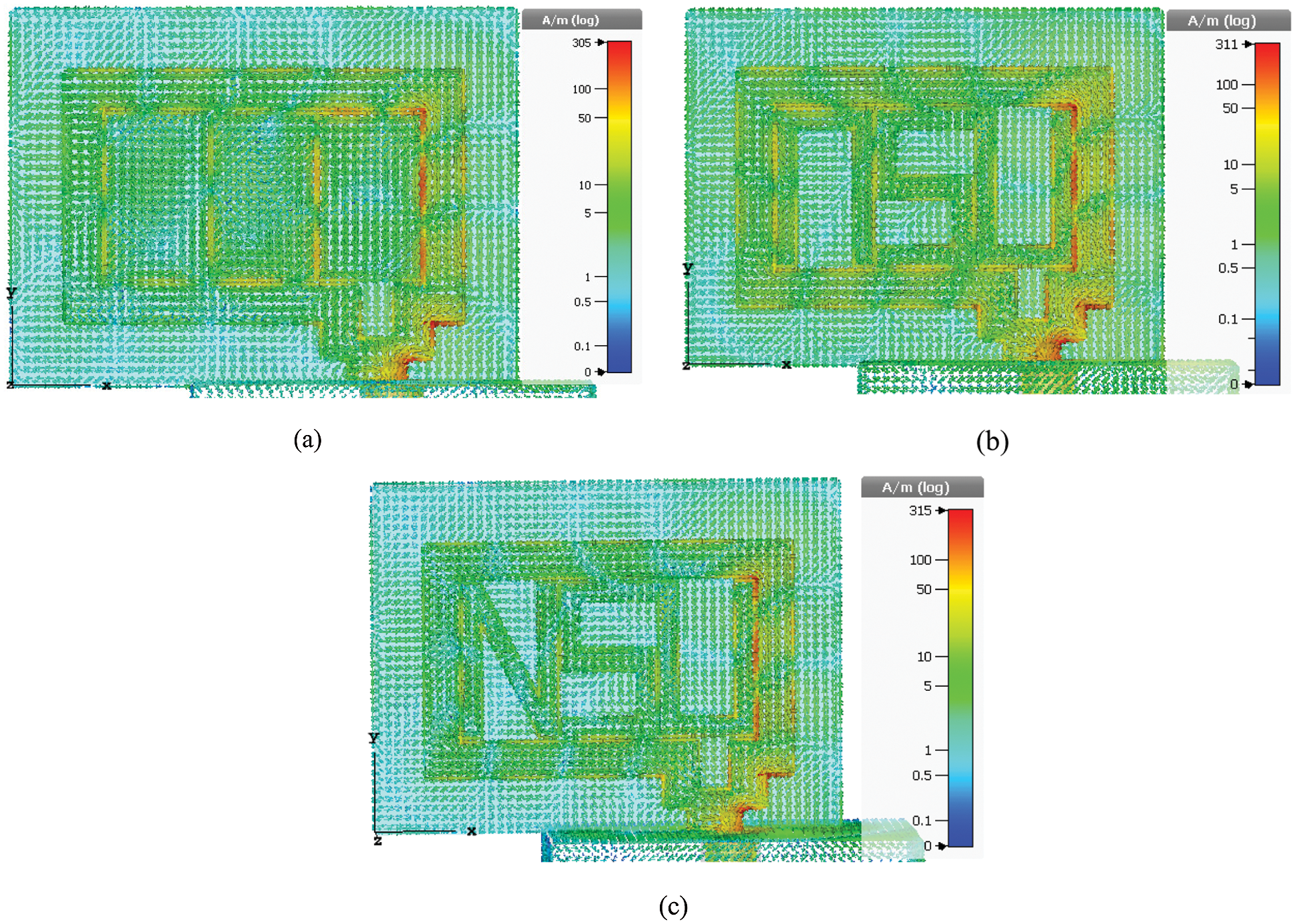
Figure 6: Coaxial feed surface current distribution at 60 GHz of (a) Design 1 (b) Design 2 (c) Design 3
In the YZ plane the magnitude of the main lobe is 8.58 dB at 19 degrees, 6.83 dB at 20°, and 7.12 dB at 20° for Design 1, 2, and 3 respectively. In the XZ plane the magnitude of the main lobe is 3.05 dB at 301°, 4.18 dB at 307°, and 4.19 dB at 330°. The maximum gain achieved by these designs with the coaxial probe is 8.64, 9.28, and 9.36 dB (Fig. 9).
3.3 On-body Simulation Results of Coaxial Feed Antennas
For on-body performance evaluation, a torso phantom is created. This phantom mimics the first three layers of a human body, which is skin, fat, and muscle (Fig. 7). The dielectric properties of the three layers are 7.98, 3.13, and 12.86. The loss tangent of skin, fat, and muscle is 1.37, 0.27, and 0.0012; see Tab. 2. For simulation purposes the dimension of skin is taken of size 55 mm × 30 mm × 1.3 mm. Fat is taken 55 mm × 30 mm × 3.7 mm and muscle is 55 mm × 30 mm × 3 mm. Therefore the total dimension of the phantom is 55 mm × 30 mm × 8 mm. The three antennas are kept at two different distances, 0 mm and 6 mm, from the phantom.

Figure 7: Antenna placed on top of the torso phantom
Table 2: Dielectric properties and loss tangents of skin, fat and muscle

Figs. 8a–8c show the free space and on-body return loss curves of three different antenna designs with coaxial feed. At 0 mm from the phantom, the center frequency of Design 1 is 60.04 GHz with a −10 dB bandwidth of 5.78 GHz. Design 2 has a center frequency of 60.06 GHz with a bandwidth of 5.05 GHz. Design 3 has a bandwidth of 5.05 GHz with a center frequency of 60.02 GHz. At a distance of 6 mm from the phantom, Design 1 has a center frequency of 59.98 GHz with a bandwidth of 5.85 GHz. Design 2 and 3 has a center frequency of 60.04 GHz and 59.98 GHz. Bandwidth at −10 dB is 5.12 and 5.11 GHz, respectively.

Figure 8: (a) Design 1 free space and on-body return loss (b) Design 2 free space and on-body return loss (c) Design 3 free space and on-body return loss
Tab. 3 shows comparison of performance parameters in free space and on-body with coaxial feed of three different designs. Due to the dielectric losses of the phantom, a drop in radiation and total efficiency is observed for all three designs at 0 mm distance. Radiation efficiency dropped to 91.96%, 92.03%, and 91.89%. Total efficiency decreased to 91.03%, 91.48%, and 91.54% for the three designs respectively. At a distance of 6 mm, the radiation efficiency increased to 94.54%, 94.47%, and 94.32%. The total efficiency increased to 93.62%, 93.96%, and 93.39%.
Table 3: Comparison of performance parameters in free space and on-body of the three antenna deigns with coaxial feed

Figs. 9a–9c and 10a–10c show the free space and on-body Three-Dimensional (3D) radiation patterns of the three different antenna designs with coaxial feed at 60 GHz. Results show that the antennas in free space show nearly directive 3D radiation patterns with siligt distortion at different angles. When the antennas are placed directly on the phantom (0 mm) the 3D radiation patterns look more directive at certian angles. Figs. 11a–11f show the radiation patterns of XZ and YZ planes for both free space and on-body for three different designs with coaxial feed at 60 GHz. At 0 mm distance, the 60 GHz radiation pattern of Design 1 in the YZ plane has a main lobe magnitude of 8.73 dB while the XZ plane has a main lobe of 2.8 dB. At 6 mm, these values are 8.01 dB for the YZ plane and 4.46 dB for the XZ plane. YZ plane of Design 2 has a main lobe magnitude of 7.12 dB at 0 mm and 6.05 dB at 6 mm. XZ plane has a main lobe magnitude of 4.81 dB and 5.26 dB at 0 mm and 6 mm respectively. YZ plane of Design 3 at 0 mm and 6 mm has a main lobe magnitude of 7.38 dB and 6.31 dB. The magnitude of the main lobe of this design’s XZ plane is 4.96 dB and 5.11 dB. Maximum gain at 0 mm is 9.4 dB, 9.77 dB and 10 dB. At 6 mm maximum gain is 8.85 dB, 10.2 dB, and 10.3 dB for the three designs.

Figure 9: Free space 3D radiation patterns of the three different antenna designs at 60 GHz (a) Design 1 (Left), (b) Design 2 (Center), Design 3 (c) (Right)

Figure 10: 3D radiation patterns of the three different antenna designs at 60 GHz when placed 0 mm away from the phantom (a) Design 1 (Left), (b) Design 2 (Center), Design 3 (c) (Right) on-body

Figure 11: Free space and on body (0 mm and 6 mm away from phantom) XZ & YZ planes radiation patterns of the antennas for three different designs with coaxial feed at 60 GHz. (a) Design 1 XZ Plane (b) Design 2 XZ Plane (c) Design 3 XZ Plane (d) Design 1 YZ Plane (e) Design 2 YZ Plane (f) Design 3 YZ Plane
The antenna design and results presented in the paper is simulation based. As mentioned earlier the antenna was designed and simulated using Computer Simulation Technology which is user friendly and the results obtained using this software is reliable. Due to lack of scope the antenna simulation results were not verified with the measurements. However it is observed that the simulation antenna results of CST software are comparable with the measurement results as reported many articles [15–29].
The main purpose of this paper is to design a 60 GHz patch antenna with three different designs to find the best design in terms of center frequency, bandwidth, efficiency, gain and radiation pattern. Performance parameters in free space and on the three layers human body model of a 60 GHz patch antenna for three different designs have been compared and analyzed. Free space performance shows that using a coaxial probe increases the bandwidth significantly and shifts the return loss curves to the right. Even though the coaxial feed introduced more gratings to the radiation pattern but it made the antennas more efficient. The 3D radiation pattern of all three designs shows that radiation is directed towards the upper region of the antenna.
If one has to choose a design for its bandwidth capacity and a more uniform radiation pattern then Design 1 is a clear choice, although the maximum gain is slightly lower than the other designs. For the on-body application, the return loss curve showed insignificant change for all the designs. Gain increased when the antennas were kept closer to the phantom. Design 2 and Design 3 have shown a similar radiation pattern with Design 1 having the maximum gain. The results are consistent with other research works.
Low interference, short-range, and high bandwidth of mm-waves makes developing devices for the medical and military fields very promising. All three antennas show very good on-body performance. Antennas presented in this work will be perfectly suitable for body-centric wireless communications.
Acknowledgement: Authors also would like to thank the Department of Electrical and Computer Engineering of North South University and Taif University Researchers Supporting Project number (TURSP-2020/36), Taif University, Taif, Saudi Arabia.
Funding Statement: Taif University Researchers Supporting Project number (TURSP-2020/36), Taif University, Taif, Saudi Arabia.
Conflicts of Interest: “The authors declare that they have no conflicts of interest to report regarding the present study.”
1. N. Guo, R. C. Qiu, S. S. Mo and K. Takahashi. (2007). “60-GHz millimeter-wave radio: Principle, technology, and new results,” EURASIP Journal on Wireless Communications and Networking, vol. 2007, no. 1, pp. 190. [Google Scholar]
2. A. M. Al-samman, M. H. Azmi and T. A. Rahman. (2018). “A survey of millimeter wave (mm-wave) communications for 5G: Channel measurement below and above 6 GHz,” in Proc. Int. Conf. of Reliable Information and Communication Technology, IRICT, Kuala Lumpur, Malaysia, pp. 451–463. [Google Scholar]
3. H. Li, K. Takizawa, B. Zhen and R. Kohno. (2007). “Body area network and its standardization at IEEE 802.15 MBAN,” in Proc. 16th IST Mobile and Wireless Communications Summit, Budapest, Hungary, pp. 1–5. [Google Scholar]
4. A. A. Thabit, M. S. Mahmoud, A. Alkhayyat and Q. H. Abbasi. (2019). “Energy harvesting Internet of things health-based paradigm: Towards outage probability reduction through inter-wireless body area network cooperation,” International Journal of Distributed Sensor Networks, vol. 15, no. 10, pp. 1–12. [Google Scholar]
5. D. A. Hammood, H. A. Rahim, A. Alkhayyat and R. B. Ahmed. (2019). “Body-to-body cooperation in internet of medical things: Toward energy efficiency improvement,” Future Internet, vol. 11, no. 239, pp. 1–13. [Google Scholar]
6. H. A. Mishmish, A. Alkhayyat, H. A. Rahim, D. A. Hammood, R. B. Ahmed et al. (2018). , “Critical data-based incremental cooperative communication for wireless body area network,” Sensors, vol. 18, no. 3661, pp. 1–19. [Google Scholar]
7. D. A. Hammood, H. A. Rahim, A. Alkhayyat, R. B. Ahmed and Q. H. Abbasi. (2018). “Reliable emergency data transmission using transmission mode selection in wireless body area network,” Cogent Engineering, vol. 5, no. 1, pp. 198–206. [Google Scholar]
8. M. M. Khan, Q. H. Abbasi, A. Alomainy and Y. Hao. (2012). “Performance of ultra wideband wireless tags for on-body radio channel characterization,” International Journal of Antennas and Propagation, vol. 2012, no. 232465, pp. 1–10. [Google Scholar]
9. P. S. Hall and Y. Hao. (2006). “Antennas and propagation for body centric communications,” in Proc. First European Conf. on Antennas and Propagation, Nice, France, pp. 1–7. [Google Scholar]
10. T. Koo, Y. Hong, G. Park, K. Shin and J. Yook. (2015). “Extremely low-profile antenna for attachable bio-sensors,” IEEE Transactions on Antennas and Propagation, vol. 63, no. 4, pp. 1537–1545. [Google Scholar]
11. A. Christ, A. Klingenbock, T. Samaras, C. Goiceanu and N. Kuster. (2006). “The dependence of electromagnetic far-field absorption on body tissue composition in the frequency range from 300 MHz to 6 GHz,” IEEE Transactions on Microwave Theory and Techniques, vol. 54, no. 5, pp. 2188–2195. [Google Scholar]
12. Y. Al-Alem and A. A. Kishk. (2018). “Simple high gain 60 GHz antenna,” in Proc. IEEE Int. Sym. on Antennas and Propagation & USNC/URSI National Radio Science Meeting, Boston, MA, USA, pp. 1693–1694. [Google Scholar]
13. Z. N. Chen, X. Qing, M. Sun, K. Gong and W. Hong. (2014). “60-GHz antennas on PCB,” in Proc. the 8th European Conf. on Antennas and Propagation (EuCAPThe Hague, Netherlands, pp. 533–536. [Google Scholar]
14. H. Vettikalladi, O. Lafond and M. Himdi. (2009). “High-efficient and high-gain superstrate antenna for 60-GHz indoor communication,” IEEE Antennas and Wireless Propagation Letters, vol. 8, pp. 1422–1425. [Google Scholar]
15. M. Li and K. Luk. (2015). “Wideband magneto-electric dipole antenna for 60-GHz millimeter-wave communications,” IEEE Transactions on Antennas and Propagation, vol. 63, no. 7, pp. 3276–3279. [Google Scholar]
16. Y. Al-Alem and A. A. Kishk. (2018). “Efficient 60 GHz antenna based on open-end Microstrip line fringing fields,” in Proc. IEEE Int. Sym. on Antennas and Propagation & USNC/URSI National Radio Science Meeting, Boston, MA, USA, pp. 1703–1704. [Google Scholar]
17. Z. Briqech and A. Sebak. (2012). “60 GHz Microstrip-fed high gain dielectric lens antenna,” in Proc. 25th IEEE Canadian Conf. on Electrical and Computer Engineering (CCECEMontreal, QC, Canada, pp. 1–4. [Google Scholar]
18. Y. Hong and J. Choi. (2018). “60 GHz patch antenna array with parasitic elements for smart glasses,” IEEE Antennas and Wireless Propagation Letters, vol. 17, no. 7, pp. 1252–1256. [Google Scholar]
19. J. Puskely, M. Pokorny, J. Lacik and Z. Raida. (2014). “Antenna implementable into button for on-body communications at 61 GHz,” in Proc. the 8th European Conf. on Antennas and Propagation (EuCAPThe Hague, Netherlands, pp. 1551–1555. [Google Scholar]
20. C. Leduc and M. Zhadobov. (2017). “Impact of antenna topology and feeding technique on coupling with human body: Application to 60-GHz antenna arrays,” IEEE Transactions on Antennas and Propagation, vol. 65, no. 12, pp. 6779–6787. [Google Scholar]
21. M. Ur-Rehman, N. A. Malik, X. Yang, Q. H. Abbasi, Z. Zhang et al. (2017). , “A low profile antenna for millimeter-wave body-centric applications,” IEEE Transactions on Antennas and Propagation, vol. 65, no. 12, pp. 6329–6337. [Google Scholar]
22. N. Chahat, M. Zhadobov, S. A. Muhammad, L. Le Coq and R. Sauleau. (2013). “60-GHz textile antenna array for body-centric communications,” IEEE Transactions on Antennas and Propagation, vol. 61, no. 4, pp. 1816–1824. [Google Scholar]
23. S. F. Jilani, M. Munoz, Q. H. Abbasi and A. Alomainy. (2019). “Millimeter-wave liquid crystal polymer based conformal antenna array for 5G applications,” IEEE Antennas and Wireless Propagation Letters, vol. 18, no. 1, pp. 84–88. [Google Scholar]
24. S. F. Jilani and A. Alomainy. (2016). “Planar millimeter-wave antenna on low-cost flexible PET substrate for 5G applications,” in Proc. 10th European Conf. Antennas Propag. (EuCAPDavos, Switzerland, pp. 1–3. [Google Scholar]
25. A. Alomainy, Y. Hao and F. Pasveer. (2007). “Numerical and experimental evaluation of a compact sensor antenna for healthcare devices,” IEEE Transactions on Biomedical Circuits and Systems, vol. 1, no. 4, pp. 242–249.
26. A. Alomainy, Y. Hao and D. M. Davenport. (2007). “Parametric study of wearable antennas varying distances from the body and different on-body positions,” in IET Seminar on Antennas and Propagation for Body-centric Wireless Communications. London, UK, 84–89.
27. Q. H. Abbasi, M. M. Khan, S. Liaqat, M. Kamran, A. Alomainy et al. (2013). , “Experimental investigation of ultra wideband diversity techniques for on-body radio communications,” Progress in Electromagnetics Research C (PIERC), vol. 34, pp. 165–181.
28. M. M. Khan, Q. H. Abbasi, A. Alomainy, C. Parini and Y. Hao. (2011). “Dual band and dual mode antenna for power efficient body-centric wireless communications,” in Proc. IEEE Int. Sym. on Antennas and Propagation (APSURSISpokane, WA, USA, pp. 396–399.
29. B. Yeboah-Akowuah, P. Kosmas and Y. Chen. (2017). “A Q-slot monopole for UWB body-centric wireless communications,” IEEE Transactions on Antennas and Propagation, vol. 65, no. 10, pp. 5069–5075. [Google Scholar]
 | This work is licensed under a Creative Commons Attribution 4.0 International License, which permits unrestricted use, distribution, and reproduction in any medium, provided the original work is properly cited. |