DOI:10.32604/csse.2021.013898
| Computer Systems Science & Engineering DOI:10.32604/csse.2021.013898 | |
| Article |
An Error-Correcting Code-Based Robust Watermarking Scheme for Stereolithographic Files
1School of Criminal Investigation, People’s Public Security University of China, Beijing, 100038, China
2School of National Security, People’s Public Security University of China, Beijing, 100038, China
3School of Electronic Information Engineering, Taiyuan University of Science and Technology, Taiyuan, 030024, China
*Corresponding Author: Huawei Tian. Email: hwtian@live.cn
Received: 30 August 2020; Accepted: 21 November 2020
Abstract: Stereolithographic (STL) files have been extensively used in rapid prototyping industries as well as many other fields as watermarking algorithms to secure intellectual property and protect three-dimensional models from theft. However, to the best of our knowledge, few studies have looked at how watermarking can resist attacks that involve vertex-reordering. Here, we present a lossless and robust watermarking scheme for STL files to protect against vertex-reordering attacks. Specifically, we designed a novel error-correcting code (ECC) that can correct the error of any one-bit in a bitstream by inserting several check digits. In addition, ECC is designed to make use of redundant information according to the characteristics of STL files, which introduces further robustness for defense against attacks. No modifications are made to the geometric information of the three-dimensional model, which respects the requirements of a high-precision model. The experimental results show that the proposed watermarking scheme can survive numerous kinds of attack, including rotation, scaling and translation (RST), facet reordering, and vertex-reordering attacks.
Keywords: Three-dimensional watermarking; stereolithographic file; robust watermarking; error-correcting code
In recent years, three-dimensional (3D) printing technology [1] has become an area of intense research and development, which has resulted in the widespread application of 3D models among others. Increasingly, sensitive information related to 3D models is transmitted over both wired and wireless networks, which raises pressing information security issues such as illegal copying, tampering and dissemination [2–4]. As such, the copyright protection of 3D models has attracted great attention.
The question of how to prevent criminals from maliciously tampering and copying unauthorized 3D digital multimedia while safeguarding the legitimate interests of producers and consumers is a difficult to answer problem for both academics and industry professionals [5,6]. Digital watermarking technology, which was introduced to prevent this type of infringement, embeds the copyright information into digital multimedia [7]. Embedded information can only be extracted by specific methods and can therefore be applied to intellectual property protection.
The first 3D model digital watermarking technology was proposed by Ohbuchi et al. [8]. Several watermarking algorithms [9–13] have been proposed based on the concepts of modified vertices and modified topological relationships. Researchers conducted a series of schemes for on-grid watermarking, leading to many 3D model-based digital watermarking algorithms being produced [8–32]. The 3D watermarking algorithm can also be divided into spatial domain watermarking (such as modifying the positions of mesh vertices) [8–24] and spectral domain watermarking (such as spectral decomposition of the mesh) [25–28], in a way similar to the image watermarking algorithm.
The stereolithographic (STL) 3D model lacks topological information compared with the traditional 3D model. Many vertices are repeatedly recorded, which makes it difficult to study it as a watermarking technology. Few studies, to the best of our knowledge, claimed to counteract facets and vertex-reordering attacks. We have designed a novel Error-Correcting Code (ECC) to solve this problem. We embed a bitstream into the 3D model and use an error-correcting code to adjust the order of the vertices in each facet, which means that any one-bit error can be repaired. The original or attacked STL 3D model is also preprocessed to obtain a standard sequence of triangular facets to facilitate extraction. The watermark information is corrected and extracted from the order of vertices according to a novel systematic approach. The watermark not only is easy to embed and extract but also performs well in terms of transparency. The proposed scheme satisfies the requirements of a high-precision 3D model.
The subsequent parts of this paper are organized as follows. In Section 2, related work is presented. Section 3 describes the proposed ECC. The implementation of the proposed watermarking scheme is detailed specifically in Section 4. The experimental results are shown in Section 5, and the directions for future research are described in Section 6.
Watermarking in the spatial domain directly modifies the geometrical attributes or topological structures of the 3D model to embed the watermark information. The earliest spatial domain watermarking algorithms include the triangle similarity quadruple (TSQ) [8,9,11,13] algorithm and the tetrahedral volume ratio (TVR) [8,11,13] algorithms, which was proposed by Ohbuchi et al. [8]. These algorithms provide a way to further study the digital watermarking of 3D models. However, they are not robust enough, and can only resist some attacks such as affine transformation.
Benendens et al. [14] proposed a 3D watermarking algorithm for adjusting the vector distribution of the mesh facet of normal vectors. Such a scheme is stable under mesh simplification attack because these normal vectors can roughly describe the trend of the meshes, this scheme is stable under mesh simplification attack. Later, Benedens et al. also proposed the affine invariant embedding (AIE) algorithm and the normal bin encoding (NBE) algorithm [15], while a priori data information needs to be given before the watermark is extracted. Benendens [16] developed the GEOPARK system based on the above algorithm for embedding watermarking in a 3D model and a virtual scene. In the same year, Wanger [17] proposed a robust watermarking of polygonal meshes. The algorithm applies to the robust watermarking algorithm of 3D polygon mesh models with arbitrary topologies, but it is insufficient for a re-meshing operation.
A solution that is a 3D model watermarking algorithm for modifying the distance from the geometric center of a model to vertices proposed by Yu et al. [18]. The algorithm can resist common attacks, but the embedded strength of the algorithm should not be too large; otherwise, it will change the models. Yu et al. provided a new embedding primitive for the research into 3D watermarking algorithms, which is a global geometric feature of the distance from the geometric center of a model to the apex.
Subsequently, Zhang et al. [19] proposed a 3D watermarking algorithm based on geometric features. This method embedded a watermark on the Discrete Cosine Transform (DCT) coefficients of distances from the vertices to the geometric center. Liu et al. [20] embedded a watermark on the DFT coefficient of the distance from vertices to the geometric center. This type of algorithm converts the distance from the geometric center of a model to the vertices to the transform domain, and embeds the watermark on the transform domain coefficients. The robustness of these algorithms has been relatively enhanced. However, these algorithms still have no power for geometric attacks such as scaling and rotation, and need to be relocated before extracting the watermark.
Peng et al. [21] proposed a watermarking algorithm based on singular value decomposition for triangular facet models. The main idea of this algorithm is to embed the watermark into a place where the singular value is zero. This algorithm successfully resisted the explain attack. Bors et al. [22] proposed a 3D model watermarking algorithm with minimal facet distortion. This watermarked 3D model has good transparency. Zhan et al. [23] proposed a blind watermarking algorithm based on vertex curvature of the model. This scheme uses the local feature vertex curvature of the 3D model as the embedding primitive, which ensures good transparency and makes the model robust to commonly used attacks. Molaei et al. [24] proposed a blind watermarking algorithm based on facet classification and sorting. This algorithm is robust enough to noise, smoothing, quantization, and clipping attacks and is resistant to geometric transformations, vertex-reordering, and facet reordering. However, the embedding process is complicated, and despite the alternations of geometric information is as slight as possible, it still has problems meeting the requirements of high-precision research fields despite the slight alterations to geometric information.
Several studies have been reported in the field of spectral domain watermarking, also, several works have been done. Ohbuchi et al. [10] proposed a non-blind method (inserted modulation of the low and medium frequency coefficients), while Cayre et al. [25] described a semi-blind method (quantization of the low and medium frequency coefficients). The research had to divide the original mesh into several patches possessing fewer vertices to reduce rapidly increasing computation time. They proposed a pre-processing step of resampling at the extraction to recover completely the same connectivity as the cover mesh, which helped to gain better resistance to changes in connectivity. Wu and Kobbelt [26] reported an algorithm that is based on radial basis functions. The construction of these basic functions corresponds to the geometric information. It significantly saves calculation time and is still stable under various attacks. With a similar objective to solve the computation performance issue, Murotani and Sugihara [27] proposed a method to watermark the mesh singular spectral coefficients with a similar objective to solve the computation performance issue. In this work, the matrix to be diagonalized has a much lower dimension. The current 3D mesh spectral analysis tools are not efficient enough, but they provide an opportunity to directly transplant the existing mature spectral watermarking techniques of images [28].
An STL file is a 3D data format for representing geometric models with triangular facets. The STL file describes a raw, unstructured triangulated facet as the unit containing normal and vertices about the triangles via the 3D Cartesian coordinates. The geometric information of a triangular facet includes the outer normal vector and the coordinates of three vertices arranged by the right-hand rule. The coordinate information of vertices is repeatedly recorded in multiple triangle facets since the STL file is composed of a series of triangular facets arranged in a disordered manner. Data redundancy is considerable, which results in inefficiency searches, queries, and modification [29].
The STL file has become one of the standard formats of data interfaces in the manufacturing field since it has a simple data structure, high computational efficiency, and good and adaptable topology, and compatibility, it has become one of the standard formats of data interfaces in the manufacturing field [30]. At the same time, however, the STL file loses its original topological relationships, and the repeated recording of vertices causes significant data redundancy. Lack of topological relationships and redundancy of data pose significant challenges to the embedding of the watermark. Moreover, it is difficult to make the traditional 3D watermarking robust on the STL file. In particular, it is challenging to resist facet- and vertex-reordering attacks. Therefore, it is difficult to embed watermarking based on geometric information to ensure robustness without distortion. Currently, there is little research into the watermarking of STL files, whereas grid models have received significantly more attention.
Cui et al. [29] proposed a watermarking algorithm based on pyramid technology for STL 3D model. The transparency of the algorithm is higher, and its robustness is much higher under blind detection. However, the embedded process needs to re-establish topological relationships. Also, relocation and resampling are required when extracted. Li et al. [32] designed two high-capacity and lossless watermarking algorithms based on an STL file, but the watermark was vulnerable to attack. The reordering attacks on the facets and vertices of the model will result in incorrect extraction of the watermarking information.
The ECC encoding scheme includes encoding part and decoding part, wherein the encoding part consists of three steps, and the decoding part is a two-step process. The encoding part first encodes the binary sequence using two-digit encoding for subsequent operations. It then inserts the check digits for the first time in order to construct “units” with the error correction function. Finally, the encoding part inserts the check digits for the second time in order to correct the random error in all cases. The decoding part first corrects the sequence and subsequently removes all redundant information. In this way, any one-bit error can be found and corrected.
Several concepts must be clarified to provide better knowledge of the coding scheme. The set of digital elements between each check digit is called a “unit,”, and the check digit is not included in the unit at any time. A unit here includes the set of digital elements between check digits. An attack here refers to any one-bit error in the binary watermark information that can change a coded bit into a check digit, and vice versa.
Our scheme locates and corrects errors of watermark information by looking at two aspects, i.e., the value of digital elements and the number of check digits. At the same time, the error correction function is completed by noting the consistency between the units and the non-repetition in the units. Redundant information, such as numbers and check digits, is inserted to locate and correct the attacked unit. A watermarked sequence that represents copyright information with length  can be represented as
  , where
  , in particular. If
  is an odd number, a “0” will be added at the end of the array.
We first encode the binary facet sequence by two-digit encoding to better implement ECC encoding. The adjacent two bits constitute a group. The watermarked sequence  is encoded as follows, where “00” is coded as “1”, “01” is coded as “2”, “10” is coded as “3”, and “11” is coded as “4”. Thus, we obtain the watermarked sequence
  , where
  .
.
The illustration of a binary watermark information  is shown in Fig. 1. The original watermark information sequence
  is obtained by two-digit coding.

Figure 1: Original sequence from binary encoding
We define two kinds of repetition, namely adjacent repetition (the current digit is exactly equal to the previous digit) and neighbor repetition (the current digit is repeated with a certain number in the previous unit) to better set the rule. The details are shown in Fig. 2.

Figure 2: Display for adjacent repetition and neighbor repetition
3.1.2 Insert the Check Digits for the First Time
The check digits are inserted between adjacently repeated digits or neighbors in the watermarked sequence to equip the units with the error-correction function.
A check digit is first inserted in the middle of the two duplicated numbers in the case of adjacent repetition. Next, the latter duplicated number is changed into its paired number (Since the vertices of any one triangular facet are rearranged, the numbers “1” and “4”, “2” and “3” in the random watermark sequence cannot be changed and replaced with each other, and they are treated as paired numbers. “1” and “4” are paired numbers; likewise “2” and “3” are paired numbers likewise). A check digit is inserted before the repetition number in the case of neighbor repetition. Next, the end number of the upper unit is added to obtain the checked watermarked sequence  .
.
The symbol “*” is used as a descriptor of the check digit. The way to code “*” is shown in Section 4.1.2. If we consider the original sequence “1 2 3 4 1 1 3 2 4”, there is no repetition in the first four bits “1 2 3 4,” and they are directly encoded (Fig. 3). The fifth “1” and the first “1” create a situation of neighbor repetition. The check digit is inserted, and the “4” at the end of the upper unit is repeated. At this time, the “1” of the sixth bit to be encoded in the original sequence and the “1” of the seventh bit in the encoding sequence lead to an adjacent repetition. The check digit is inserted, and the “1,” which is to be inserted becomes its paired number “4.” In this way, we get the first encoding sequence  .
.

Figure 3: Inserting the check digit for the first time
3.1.3 Insert the Check Digits for the Second Time
We insert the check digits for the second time to retain the error-correction function in some special cases and to make it more robust. The continuous watermarked sequence  is separated by check digits after the first check digit insertion. The value of elements of a unit is smaller than 5 and the length of the elements in a unit is less than 4.
① In the watermarked sequence  , when there might be two, three or four elements might be present in one single unit. Therefore, different numbers of check digits are respectively inserted in according to different situations. If there are two elements in a unit, the number of inserted check digits corresponds to the value of an element that is at the end of the unit; if there are three elements in a unit, the number of inserted check digits corresponds to the sum of the second and third elements of the unit; when there are four elements in a unit, if the middle two digits are in an order of increasing magnitude, for example, “1, 2,” “1, 3,” “1, 4,” “2, 3,” “2, 4,” “3, 4,” a check digit will be inserted again. Otherwise, two check digits are inserted.
② Only if the digits before and after the check digit(s) are paired numbers, will the ending element in the upper unit will be inserted again before the first check digit. A watermarked sequence  with a second check is obtained. In this case, there are one or more check digits between each unit. Moreover, the unit is still only a set of digital elements between each check digit.
As shown in Fig. 4, the first unit has 4 digits, and the third bit “3” is bigger than the second bit “2.” Therefore, so we insert just one check digit. The second unit has two digits, and the end number is “1”, in this case, a check digit is also inserted. The third unit has three numbers, and the number of check digits inserted is equal to the sum of the second bit “3” and the third bit “2”. In this way, we get the third encoding sequence  .
.

Figure 4: Inserting the check digit for the second and third times
Finally, we restore the encoded watermark sequence to binary. This yields a binary sequence  of the watermark information.
The additional check digits are help to estimate the watermark information. In this case, we can verify the information sequence that contains the watermark from both the number itself and the number of check digits. Next, we can locate the modified unit and correct it. The correction comprises three main steps. First, the binary sequence  that may contain the watermarked information is encoded by a two-bit; and the coding mode is the same as that described in Section 3.1.1. In this way, we get the watermark sequence
  .
.
Sub-step 1: If the attacked bit is by coincidence to be a check digit, there will be an odd number of binary codes in a unit and the encoding of the unit fails (Fig. 5). In this case, two situations are possible. All the modifications made in this case are performed in the binary sequence of the unit that fails in coding. If the verification is passed, then the number of check digits matches the digital value. This situation is not discussed further. The two other situations are discussed in detail as follows.
1) The attacked unit includes only one bit.

Figure 5: The example of the attacked unit
Two states contribute to this situation (Fig. 6). The first state is that the extra original odd digit originally is a check digit. This digit becomes a coded bit after it is attacked. The second state is that the first or the last digit in the unit is attacked and subsequently becomes the check digit. The following judgment is necessary to locate the attack.

Figure 6: Two states of the first situation
First, the extra bit is changed into the check digit, and a judgement is made as to whether the verification is passed. The modification is correct if the verification step is passed. Otherwise, the extra bit should be modified according to the last digit of the upper unit or the first digit of the next unit.
The two digits before and after the check digits can only be the same or paired. When one of these digits has an error, it can be modified according to another digit.
The modification process is altered as described in 2) III if this verification does not allow the verification to pass.
2) The attacked unit includes more than one bit.
Two states may result in this type of error (Fig. 7). The first is that the last check digit of the upper unit is attacked and tampered into a coded bit. The second state is that the first check digit of the unit is attacked and tampered into a coded bit. We judge the location of the attack as described for the following three situations.

Figure 7: Three states of the second situation
① If the number of check digits of this unit or the upper unit is only one, the check digit is restored to “0” or “1” (the digit is changed to “0” first to try if it can pass the verification, if it fails to pass the verification, it is changed to “1”). It is checked as to whether the unit can pass the verification after the restoration. If not, the modification fails and enters the situation described in ②.
② In this situation, if the number of check digits in the unit and the upper unit is more than one, and the upper unit fails the verification, then the attack must happen in the upper unit. In this way, according to the digital value of this unit, the number of check digits that the unit should have is compared with the number of existing check digits to see if the check digit is missing. This determines the specific location of the attack. If the check digit is missing, it is attacked by the last check digit of the upper unit, and the check digit is changed to the coded bit, which results in the lack of a check digit. The correction simply changes the first bit of this unit to a check digit. If the check digit is not missing, the first bit of the unit is attacked, and the coded bit is changed to the check digit, which results in the check digit being redundant. The correction is required based on the last digit of the upper unit.
③ In this situation, the number of check digits of the unit and the upper unit is more than one, while only the upper unit can pass the verification, and it is can be determined that the attack has happened in this unit. This situation can arise when the last bit of the unit is changed to a check digit, or the first bit of the unit is changed to a coded bit. First, the last bit of the code in this unit is changed to the check digit. The modification is correct if it can pass the verification, the modification is correct. Otherwise, the correction is made according to the first digit of the next unit.
Sub-step 2: The number itself. The last digit of the unit must be consistent with the first digit of the next unit (this situation consists of two cases in which the connected numbers are the same and the paired), and the number in the unit cannot be repeated. However, the last two digits of the upper unit must be repeated when the last digit of the adjacent unit and the first digit of the next unit are paired with each other.
Sub-step 3: Check digits. In this situation, the number of check digits matches the value of certain digital elements in each unit (the number of check digits of this unit always refers to the number of check digits followed by the unit). In particular, the repeated number is not counted in the unit length when the last two digits of the upper unit are adjacent repetitions. The number of check digits matches the last element when there are one or two elements in a unit. The number of check digits corresponds to the sum of the second and third digits when there are three elements in a unit. When there are four elements in a unit and the second digit is bigger than the third digit, there should be just two check digits; otherwise, there should be three check digits.
The corrected watermark sequence is finally obtained by judging and correcting the non- conforming figures according to the three criteria and subsequently removing check digits and redundant information.
All check digits and the first digit of each unit in addition to the first unit are redundant due to the rules we set. All redundant information can be removed directly from the extracted sequence when decoding. The decoding scheme is simple and fast (Fig. 8) as shown for the decoding process of a corrected watermark sequence  . After the final binary step, we get the original watermark sequence
  is obtained.

Figure 8: The decoding process
4 The Proposed Watermarking Scheme for the STL File
The framework of the proposed scheme is shown in Fig. 9. It is divided into two parts: watermark embedding and extraction. The embedding part specifically includes the following three main steps: Step 1, obtain the watermarked sequence based on ECC; Step 2, sort the triangle facets of the STL model; Step 3, embed the encoded the watermark sequence. The extraction part includes the following three steps: Step 1, sort the triangle facets of the STL model; Step 2, extract the digital watermarking sequence; Step 3, verify and correct the digital watermarking sequence.

Figure 9: The framework of the proposed scheme
STL files describe only the surface geometry of a three-dimensional object without any representation of color, texture or other common computer-aided design (CAD) attributes of the model. This file format is supported by many other software packages. It is also widely used for rapid prototyping, three-dimensional printing and computer-aided manufacturing [31].
A STL file describes a raw, unstructured triangulated surface by the unit normal and vertices (ordered by the right-hand rule) of the triangles using a three-dimensional Cartesian coordinate system. The STL format specifies both ASCII and binary representations. As shown in Fig. 10, an STL file begins with the line “solid name” and the file continues with any number of triangles, each of which is represented as follows:

Figure 10: An STL file
The STL file is composed of a plurality of unordered triangular facet information units. Each of these units contains an external normal vector of the triangular facet starting with “facet normal” and the coordinate values of the three vertices of a triangle beginning with “vertex.” The STL file contains no scale information, and the units are arbitrary. The whole STL file concludes with “endsolid name.”
In the case of keeping the direction of the normal vector “n” of the triangular facet unchanged, the order of the vertices needs to conform to the right-hand rule (a counter-clockwise arrangement along the normal vector). Therefore, the triangles have only three arrangements.
The values of the three vertices are compared, and the vertex with the largest value is named A (first, the x coordinate is compared; next, the y coordinate is compared with the x coordinate to see if it is the same, compare the z coordinate when the y coordinate is the same [32]).
In addition, in a counterclockwise direction, the other two vertices are named B and C in turn. Hence, the A, B, and C points of the triangular facets are determined. In the counterclockwise direction of the normal vector, the vertices of the triangular facet have three sorting orders, and each sorting order is coded. The encoding criterion is shown in the following section, and the triangular facet is encoded by adjusting the order of vertices.
A description of step 1 is not repeated here since the entire encoding scheme has been described. We will start directly from step 2.
4.1 The Watermark Embedding Based on ECC
STL files may be attacked by facet reordering. This type of attack does not change the geometric structure of three-dimensional models nor affect the use of them. Therefore, it is necessary to sort triangular facets according to their attributes to eliminate the influence of facet-reordering attack on the watermarking system. The reordering here guarantees the consistency of triangular facets irrespective of the type of reordering attack on the STL file. In this case, we applied principal component analysis (PCA) to obtain the standard sequence of the triangular facets.
4.1.1 PCA Pretreatment of the Triangular Facet of the STL File
The coordinate values of each triangular facet in the PCA coordinate system are calculated. The corresponding triangular facets are sorted according to their values from the largest to the smallest to obtain the standardized triangular facet sequence  . This includes the following four sub-steps:
Sub-step 1: In Cartesian coordinates, the model is shifted so that the gravity center of the model coincides with the origin of the coordinate system.
Sub-step 2: Three feature vectors are obtained by PCA processing the coordinate values of the triangular facets in the model.
Sub-step 3: The model is mapped from the Cartesian coordinate system to the PCA coordinate system with three feature vectors as the coordinate axes of the PCA space.
Sub-step 4: A known triangular facet sequence  is obtained by comparing the coordinate values of the triangular facets in the model. The mean of comparison is used to compare the coordinates of the center of the triangular facet. The x coordinates are compared if the central coordinate values are the same. The y coordinates are compared if the x coordinates are the same. The z coordinates are compared if the y coordinates are the same.
4.1.2 Embedding the Watermark to the STL File by ECC
Vertices A, B and C of the triangular facet are determined by comparing the coordinate values of the triangular facets. The vertex with the largest coordinate value is named A. The vertices can only be ordered counterclockwise along the external normal vector due to the characteristics of the STL file. The other two vertices are named B and C in turn (Fig. 11).

Figure 11: An example of a triangular facet
When the A, B, and C vertices of the triangular facet are determined, there are only three sorting schemes for the vertices. Each sorting scheme is encoded. In particular, the triangular facets can be encoded by adjusting the ordering of the vertices ordering as shown in Tab. 1 in such a way that a triangular facet can accommodate 1 bit of information.
Table 1: The representation information of a triangular facet

We embedded the binary sequence  of the watermarked information by modifying the vertices of each triangular facet in the triangular facet sequence
  , we embedded the binary sequence
  of the watermarked information to obtain the covered STL 3D model. For example, if the first bit of the binary sequence
  is “0”, the first triangular facet of the triangular facet sequence
  is sequentially adjusted to “A, B, C”, so that the STL 3D model with watermarking information
  can be obtained.
4.2 The Watermark Extraction Based on ECC
First, PCA pretreatment of the triangular facets is executed as same as described in Section 4.1.1. Next, vertices A, B and C of the triangular facet are determined by comparing the coordinate values of the triangular facets. The vertex with the largest coordinate value is named A; the other two vertices are named B and C in counterclockwise order
The binary sequence  that may contain watermark information is extracted according to the order of the vertices. If the order of the first triangular facet vertices in the triangular facet sequence
  is “A, B, C,” the embedded binary watermark information is “0.” The binary sequence information
  is encoded in a group of two adjacent bits. Group “00” is coded as “1,” “01” is coded as “2,” “10” is coded as “3,” and “11” is coded as “4,” which yields the sequence
  watermark information.
An error-corrected watermark sequence  is obtained using the previously described ECC decoding rule.
  is then restored to a binary sequence to obtain the final original watermark sequence
  .
.
5 Experimental Results and Discussion
We carried out experiments on 100 STL 3D models to prove the feasibility of our watermarking algorithm. The experiments mainly included assessments of transparency, capacity and robustness. Few studies, to the best of our knowledge, describe watermarking algorithms for STL files.
In our study, we propose an ECC to resist these two types of attack by making use of the redundant information. Any one-bit error can be found and corrected by applying the ECC to the STL file. Moreover, we make no changes to the STL 3D model itself, and our watermark is therefore fully transparent. Our method is 100% resistant to conventional RST attacks as well as facet-reordering attacks. The method we use can resist a reordering attack at any one vertex.
5.1 Watermark Imperceptibility
Our scheme simply reorders the vertices within the facets. It does not modify the values of the vertices and the normal of the facets. Our scheme also does not affect the geometric information of the STL 3D model. Therefore, the watermark is completely transparent. A comparison of the original model and the covered model is shown in Fig. 12.

Figure 12: Comparison of original models and watermarked models (a) Original model. (b) The watermarked model of (a). (c) Original model. (d) The watermarked model of (c)
The number of embedded check digits is different based on the coding rules of ECC. This is due to the encoded watermark information and its length. In this case, the number of check digits depends on the code length of different states, which in turn has a large impact on the code rate. We use discrete-time Markov chains to calculate the probability of occurrence of different cases of code length and calculate the theoretical code rate.
Our rule setting results in the states of adjacent repetition (a.r.) and neighbor repetition (n.r.). The probability of the occurrence of different code lengths is shown in Tab. 2. There are seven different cases of code length as shown in Tab. 3.
Table 2: The probability of occurrence of different code lengths

Table 3: Code rate of different code lengths

We multiply the probability of occurrence of different code lengths with the corresponding code rate and divide by the eigenvector weight to obtain a theoretical code rate of 38.31%.
We used a statistical method to test the capacity of the watermark. In our experiments, we tested 100 models for 1000 times. Each model embedded a random watermark information, which had a random length between 1 and 10000 The average value of “the number of bits/the number of facets” is the capacity of the watermark. The result shows that the capacity of the watermark is 38.82% of a facet.
In this experiment, the code rate is related to both the length of the watermark information and the content of the watermark itself. The theoretical capacity is consistent with the experimental capacity within the error tolerance.
It is difficult to study the watermarking algorithm for the STL 3D model. The STL 3D model lacks information about topological structures, and has a large number of repeatedly recorded vertices. Few studies have focused on the STL 3D model, and reports about how lossless watermarking of the STL 3D model can resist facet- and vertex-reordering attacks are lacking. Our work for the STL file is, to the best of our knowledge, original and unique in this area of research, and our method can resist RST attacks as well as facet- and vertex-reordering attacks. Our proposed method has achieved very good results in resisting these types of attack, but it has not been compared with other algorithms.
Our scheme no use of the geometric information of the STL 3D model since it is only performed on the STL file. Consequently, if user of the model still wants to make the model available, the attacks like quantization, cropping, and simplifying could not be made on the STL file. In these cases, that the destruction of the structure of the model may cause the loss of its value.
The robustness of the watermark system to protect the copyright is always a concern for watermark techniques. The goal is to ensure the availability of the STL 3D model. Therefore, the damage to the models should be slight, and the weak noise and smoothness should in general not change the relative positions of the three vertices in the facets. By these criteria, our scheme is robust enough. Namely, the attacks toward STL files could only be reordering of facets and vertices. Hence, we only considered geometric attack in our experiments.
5.3.1 Rotation, Scaling and Translation Attacks
We preprocessed the STL 3D model with PCA and mapped it to PCA space to obtain the original sequence of facets. This preprocessing method enables the watermarking to resist three conventional attacks: translation, rotation and scaling. We wanted to verify the robustness of the algorithm to RST attacks, we carried the experiment on 10 STL 3D models, and calculated the correlation coefficient to show the performance, as shown in (Tab. 4). The proposed algorithm is completely robust to RST attacks.
Table 4: The result about correlation coefficient of facet-reordering simulation experiment

5.3.2 Facet-Reordering Attacks
The facet sequence is reordered before the watermark is embedded. Thus an attack that modifies the original sequence will not have any effect on the scheme in this paper.
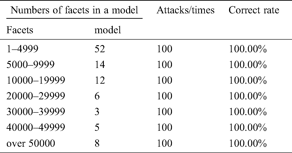
We carried out a random facet-reordering attack on 100 STL 3D models. The results showed that the attacks of facet-reordering did not have any effect on our scheme. The proposed scheme is completely robust to facet-reordering attacks. We divided the experimental models into different intervals according to the number of facets. The result is shown in Tab. 5.
Table 5: Facet-reordering simulation experiment
5.3.3 Vertex-Reordering Attacks
Any one-bit error in the order of vertices can be detected and corrected after encoding and embedding the watermark according to the scheme described in this paper.
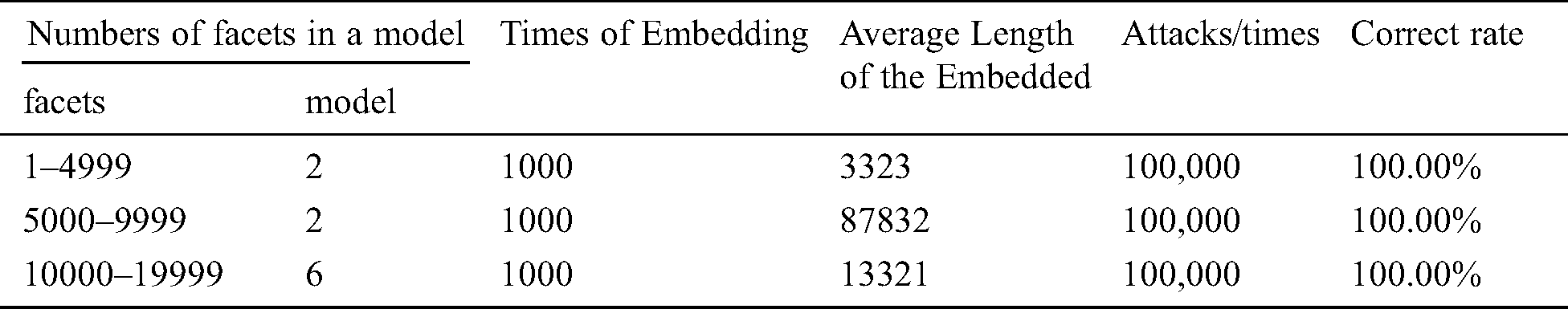
Ten different STL 3D models were used to evaluate the robustness of the proposed watermarking scheme. We embedded different watermark information for 1000 times for each STL file, and 10 random vertex-reordering attacks were applied on each embedded information. The watermark information we embedded had a random length between 1 and 20,000. In all of the aforementioned 100,000 random attacks, all of them can correctly extract the watermark and correct the information carried by the attack facets. The correct extraction rate is 100%. More details are shown in Tab. 6. The proposed watermarking scheme can resist against vertex-reordering attacks successfully.
Table 6: Vertex-reordering simulation experiment
We proposed a robust watermarking for STL files based on our ECC that counters facet- and vertex-reordering attacks. The scheme differs from conventional watermark embedding by altering the geometric information of models. We make use of redundant information in the STL file to embed the watermark for copyright protection of STL into 3D models. This is to the best of our knowledge the first time this type of approach has been used STL files. The proposed method is fully resistant to conventional RST attacks as well as facet and single-vertex attacks. Moreover, the scheme achieves an appropriate trade-off between the robustness and transparency of the watermark. Although the embedded watermark has modified the order of triangular facet vertices, the geometric information of the 3D model has not been modified, and the data of facets can be precisely analyzed and detected. The new method meets the requirements necessary for content integrity and precision military, medical, legal and other precision fields.
Acknowledgement: We thank LetPub (www.letpub.com) for its linguistic assistance during the preparation of this manuscript. Special thanks to the Zhaojun Lan from Capital Normal University, who may not be able to successfully complete the mathematical statistics calculation without her help. We are also grateful to Zhiyin Xu from PPSUC for his contribution to article, as well as the help and encouragement given during the completion.
Funding Statement: This work was supported in part by the National Science Foundation of China (No. 61772539, 6187212, 61972405), STITSX (No. 201705D131025), 1331KITSX, and CiCi3D.
Conflicts of Interest: The authors declare that they have no conflicts of interest to report regarding the present study.
1. X. L. Li, J. X. Ma, P. Li, Q. Chen and W. M. Zhou. (2014). “3D printing technology and its application trend,” Process Automation Instrumentation, vol. 35, no. 1, pp. 1–5. [Google Scholar]
2. H. W. Tian, Y. H. Xiao and G. Cao. (2016). “Robust watermarking of mobile video resistant against barrel distortion,” China Communications, vol. 13, no. 9, pp. 131–138. [Google Scholar]
3. F. Han. (2016). “Research on adaptive 3D color image watermarking algorithm based on improved visual model. M.S. thesis, Dept. C.S., Shandong Normal University, Shandong, China. [Google Scholar]
4. H. W. Tian, Y. Zhao, R. R. Ni, L. M. Qin and X. L. Li. (2013). “LDFT-based watermarking resilient to local desynchronization attacks,” IEEE Transactions on Cybernetics, vol. 43, no. 6, pp. 2190–2201. [Google Scholar]
5. X. Y. Wang. (2017). “Research on digital watermarking techniques for copyright protection of three-dimensional mesh models,” Ph.D. dissertation. Dept. Computer. Application. Technology, Jiangsu University, Jiangsu, China. [Google Scholar]
6. Y. Q. Bai, G. Y. Jiang, H. Jiang, M. Yu, F. Chen et al. (2018). , “Novel robust high dynamic range image watermarking algorithm against tone mapping,” KSII Transactions on Internet & Information Systems, vol. 12, no. 9, pp. 4389–4441. [Google Scholar]
7. J. H. Liu and Y. B. Rao. (2019). “Optimization-based image watermarking algorithm using a maximum-likelihood decoding scheme in the complex wavelet domain,” KSII Transactions on Internet & Information Systems, vol. 13, no. 1, pp. 452–472. [Google Scholar]
8. R. Ohbuchi, H. Masuda and M. Aono. (1997). “Watermarking three-dimensional polygonal models,” ACM Multimedia, vol. 97, pp. 261–272. [Google Scholar]
9. R. Ohbuchi, H. Masuda and M. Aono, “Watermarking multiple object types in three-dimensional models,” in Multimedia and Security Workshop at ACM Multimedia, vol. 98, pp. 12–13, 1998. [Google Scholar]
10. R. Ohbuchi, A. Mukaiyama and S. Takahashi. (2003). “A frequency-domain approach to watermarking 3D shapes,” in Proceedings of Computer Graphics Forum, Oxford, UK: Blackwell Publishing, vol. 21, no. 3. [Google Scholar]
11. R. Ohbuchi, H. Masuda and M. Aono. (1998). “Data embedding algorithms for geometrical and non-geometrical targets in three-dimensional polygonal models,” Computer Communications, vol. 21, no. 15, pp. 1344–1354. [Google Scholar]
12. R. Ohbuchi, H. Masuda and M. Aono. (1997). “Embedding data in 3D models,” in Proc. of International Workshop on Interactive Distributed Multimedia Systems and Telecommunication Services, Berlin, Heidelberg: Springer, pp. 1–10. [Google Scholar]
13. R. Ohbuchi, H. Masuda and M. Aono. (1998). “Watermarking three-dimensional polygonal models through geometric and topological modifications,” IEEE Journal on Selected Areas in Communications, vol. 16, no. 4, pp. 551–560. [Google Scholar]
14. O. Benedens. (1999). “Geometry-based watermarking of 3D models,” Fraunhofer Inst for Computer Graphics Darmstadt Virtual Reality Demonstration Centre, Germany. [Google Scholar]
15. O. Benedens. (1999). “Two high capacity schemes for embedding public watermarks into 3D polygonal models,” in Proc. of the Multimedia and Security-Workshop at ACM Multimedia, Orlando, Florida, vol. 99. [Google Scholar]
16. O. Benedens. (2001). “GEOMARK-watermarking technology for 3D models and virtual scenes,” Computer Graphik Topics, vol. 13, no. 1, pp. 20–21. [Google Scholar]
17. M. G. Wagner, “Robust watermarking of polygonal meshes,” in Proc. of Geometric Modeling and Proc. of 2000 Theory and Applications, pp. 201–208, Hong Kong, April 10–12, IEEE, 2000. [Google Scholar]
18. Z. Yu, H. H. S. Ip and L. F. Kwok. (2003). “A robust watermarking scheme for 3D triangular mesh models,” Pattern Recognition, vol. 36, no. 11, pp. 2603–2614. [Google Scholar]
19. J. Zhang and G. Q. Zheng. (2005). “A geometry property based watermarking scheme for three dimensional meshes,” Journal of Computer-Aided Design & Computer Graphics, vol. 17, no. 4, pp. 740–747. [Google Scholar]
20. W. Liu and S. H. Sun. (2006). “DFT based robust digital watermarking algorithm for 3d mesh mode,” Computer Engineering and Applications, vol. 42, no. 14, pp. 192–196. [Google Scholar]
21. W. Peng, Q. G. Ji, N. Mou and G. Q. Li. (2009). “Non invertible watermarking scheme for 3d meshes,” Journal of Image and Graphics, vol. 14, no. 7, pp. 1418–1425. [Google Scholar]
22. A. G. Bors and M. Luo. (2013). “Optimized 3D watermarking for minimal surface distortion,” IEEE Transactions on Image Processing, vol. 22, no. 5, pp. 1822–1835. [Google Scholar]
23. Y. Z. Zhan, Y. T. Li, X. Y. Wang and Y. Qian. (2014). “A blind watermarking algorithm for 3D mesh models based on vertex curvature,” Frontiers of Information Technology & Electronic Engineering, vol. 15, no. 5, pp. 351–362. [Google Scholar]
24. Molaei, A. Masoud, H. Ebrahimnezhad and M. H. Sedaaghi. (2016). “Robust and blind 3D mesh watermarking in spatial domain based on faces categorization and sorting,” 3D Research, vol. 7, no. 2, pp. 11. [Google Scholar]
25. F. Cayre, P. Rondao-Alface, F. Schmitt, B. Macq and H. Maî.tre. (2003). “Application of spectral decomposition to compression and watermarking of 3D triangle mesh geometry,” Signal Processing: Image Communication, vol. 18, no. 4, pp. 309–319. [Google Scholar]
26. J. H. Wu and L. Kobbelt. (2005). “Efficient spectral watermarking of large meshes with orthogonal basis functions,” Visual Computer, vol. 21, no. 8–10, pp. 848–857. [Google Scholar]
27. M. Kohei and K. Sugihara. (2003). Watermarking 3D polygonal meshes using the singular spectrum analysis. Mathematics of Surfaces, vol. 2768. Berlin, Heidelberg: Springer, 85–98. [Google Scholar]
28. K. Wang, G. Lavoué, F. Denis and A. Baskurt. (2007). Three-Dimensional meshes watermarking: Review and attack-centric investigation. International Workshop on Information Hiding, vol. 4567. Berlin, Heidelberg: Springer, 50–64. [Google Scholar]
29. H. G. Cui, J. X. Liu and Z. M. Li. (2013). “STL model watermarking algorithm based on pyramid technique,” Acta Automatica Sinica, vol. 39, no. 6, pp. 852–860. [Google Scholar]
30. S. Gao, Z. Wang, T. Y. Wang, Z. Q. Yu and C. L. Liu. (2018). “Calculating normal vector of measurement point for stl model in on-machine measurement system,” Mechanical Science and Technology for Aerospace Engineering, vol. 8, pp. 1231–1238. [Google Scholar]
31. C. K. Chua and K. F. Leong. (2014). “3D Printing and additive manufacturing: Principles and applications (with companion media pack) of rapid prototyping,”Fourth Edition,World Scientific Publishing Company,Singapore, pp. 303–308. [Google Scholar]
32. J. Li. (2015). “Research on the lossless watermarking algorithm for STL model.” M.S. thesis, Dept. C.S, Hunan University, Hunan, China. [Google Scholar]
 | This work is licensed under a Creative Commons Attribution 4.0 International License, which permits unrestricted use, distribution, and reproduction in any medium, provided the original work is properly cited. |