DOI:10.32604/csse.2021.014469
| Computer Systems Science & Engineering DOI:10.32604/csse.2021.014469 | |
| Article |
Research on the Novel Honeycomb-Like Cabin Based on Computer Simulation
School of Mechanical and Electrical Engineering, Qingdao University of Science and Technology, Qingdao, 266061, China
*Corresponding Author: Yongyan Wang. Email: wangyongyan168@163.com
Received: 22 September 2020; Accepted: 25 October 2020
Abstract: The antiknock capability and thermal protection performance of rescue capsules mainly depend on the structural design of the cabin. By designing a new type of cabin structure, it can resist the impact of explosion shock waves and thermal shocks. In this paper, a new honeycomb-like cabin is proposed; the model has a novel thermal insulation layer design. Then, the antiknock capabilities and thermal protection analysis are carried out by using computer software. The “Autodyn” analysis module in ANSYS Workbench 17.0 has been used to simulate the explosion of TNT with a certain quality in a single room. The pressure map over time and the pressure variation curve at different locations for a single room are obtained. Through the analysis module “Transient Structural,” the stress and deformation of the honeycomb-like cabin under the blast load are simulated. The “Transient Thermal” analysis module in the finite element software is used to conduct a transient thermal analysis on the cabin structure. The temperature map and the temperature rise curve of each layer of the cabin cases are obtained. The analysis results indicate that the honeycomb-like cabin design has a good antiknock capability and thermal protection performance, and it can meet the usage requirements of the rescue capsule under dangerous conditions.
Keywords: The rescue capsule; computer; the honeycomb-like cabin; the antiknock ability; the thermal protection; the thermal insulation layer
The rescue capsule is a closed cabin with a certain volume, which can protect the lives of escaped persons in the event of a disaster [1]. The rescue capsule must not only have resistance to pressure and shock forces, but also have a good antiknock capability and thermal protection performance [2,3].
For the research on the design, the antiknock capability and the thermal protection performance of the rescue capsule, many strong scientific research organizations invested substantial manpower and funds. Safety policies and corresponding standards for rescue capsules were proposed over the last four decades [4–6]. In the 1980s, Japan developed the first escape device called Suleda 125 to address the fire rescue escape problem of high-rise buildings [7]. The MineARC company in Australia designed and developed a large number of lifesaving cabins and applied them in the mining industry [8]. The Strata company in the United States developed a fully functional lifesaving cabin for mines, which has been successfully used in more than 30 coal mines. This product was equipped with an air cleaning device and a long-term oxygen supply system [9]. Research on the antiknock capability of the rescue capsule included the work by Janovsky et al. These authors used “Auto Rea Gas” to simulate the entire process of a Gas Explosion in a mine where the concentration of TNT was 9.5%. By comparing the simulation and experimental results, it was found that the results were similar [10]. Gantes et al. proposed an elastic–plastic response spectra for exponential blast loading [11]. Zineddin and Jacinto studied the failure law and dynamic response of plates under blast loading through experimental and computational analysis [12,13]. Yu et al. obtained the diffusion law of indoor gas under different influencing factors by numerical simulation; these authors analyzed and calculated the results after the explosion [14]. Go et al. used Fluent to simulate the movement law of the explosion shock wave propagation, and they obtained the distribution law of the pressure field and the temperature field in a coal lane after the TNT explosion [15]. Dou Hongying conducted a study on the blast resistance of a mine-used lifesaving cabin [16]. Research on the thermal protection performance of the rescue capsule included Zhai et al. in which the thermomechanical coupling effect on a certain structure subjected to gas explosion was analyzed [17]. Li and Du conducted the antiknock and transient thermal analysis for a capsule using a decoupling method [18,19]. Bai discussed the high temperature impact resistance of the capsule using a thermal analysis module in ABAQUS; the variation laws of temperature on the outer surface, thermal insulation layer, and inner surface were simulated and deduced [20]. Wang et al. conducted a transient thermal analysis of the thermal insulation layer of the rescue capsule through the finite element software. These authors obtained the temperature distribution of the rescue capsule [21].
Although many researchers have conducted substantial analysis and research on the rescue capsule, some problems remain. The structural design of the rescue capsule has limitations. Some cabins consider the resistance to pressure, but ignore its space utilization; some cabins consider the space utilization, but ignore its resistance to pressure. In the design of the thermal insulation layer, the selection of the thermal insulation material is not appropriate, and the design of the thermal insulation layer is too complex. The analysis of the antiknock ability of the cabin is limited as the boundary condition and the analysis method are too simple.
In this paper, the advantages and disadvantages of the cabin structure of the existing rescue capsule are analyzed, a new type of honeycomb-like cabin is proposed, and the thermal insulation layer of the cabin is designed. Then, the antiknock capabilities and thermal protection analysis are carried out by using computer software. The “Autodyn” is used to simulate the explosion of TNT with a certain quality in a single room, and the “Transient Structural” is used to simulate the stress and deformation of the honeycomb-like cabin under a blast load. Under two different boundary conditions, the thermal protection performance of the cabin of the rescue capsule is analyzed. Using the temperature rise curve, the transient thermal analysis of the cabin is conducted. It is verified that the honeycomb-like cabin can meet the requirements of the antiknock capability and the thermal protection performance.
2 Rescue Capsule’s Cabin Design
The geometries of cabins in existing rescue capsules are diverse, including spherical, arched, square, and so on. In testing the resistance to pressure of the cabins, the spherical cabin has the best performance. The arched cabin follows, and the square cabin has the lowest resistance to pressure [22,23]. However, in testing the space utilization of the cabins, the square cabin has the best results. The arched cabin follows, and the spherical cabin has the lowest utilization. The honeycomb structure, composed of many regular hexagonal cells, has an excellent geometrical structure and mechanical performance. This structure is strong, lightweight, and good for sound and heat insulation. On the basis of the existing rescue capsules and honeycomb structure, this paper innovatively proposes the honeycomb-like cabin structure. Under the guarantee of high space utilization, it improves the resistance to pressure, reduces the deformation, and reduces the stress concentration of the cabin. Fig. 1 shows a model diagram of the honeycomb-like cabin structure.
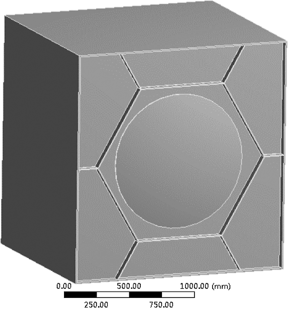
Figure 1: The model diagram of the honeycomb-like cabin structure
3 Thermal Insulation Layer Design
3.1 Selection of Thermal Insulation Material
With the development of the aerospace industry, the requirements for thermal insulation materials are becoming increasingly stringent. Thermal insulation materials must not only have the basic thermal insulation capacity, but also have the performance of sound insulation, vibration reduction and corrosion protection [24,25]. According to the working environment of the rescue capsule and the thermal insulation effect to be achieved by the thermal insulation layer, Aerogel Blanket is selected as the material for the thermal insulation layer. This material has a superior thermal insulation effect. Fig. 2 is a comparison diagram of the thermal conductivity of the aerogel and traditional materials at different temperatures.
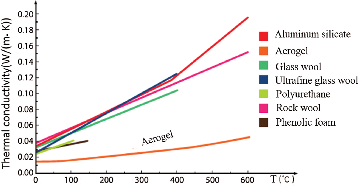
Figure 2: The comparison diagram of thermal conductivity of aerogel and traditional materials at different temperatures
3.2 Structural Design of the Thermal Insulation Layer
In this paper, the Aerogel Blanket is selected as the thermal insulation layer of the rescue capsule, and its thickness is initially designed to be 120 mm. The Aerogel Blanket is attached to the inner side of the outer shell and pressed with a pressure plate. The pressure plate, Aerogel Blanket, and the outer shell are connected together by screws. Fig. 3 is a schematic structural diagram of the thermal insulation layer, in which 1 is the outer shell, 2 is the thermal insulation layer (Aerogel Blanket), and 3 is the pressure plate.
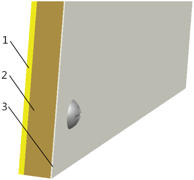
Figure 3: The schematic structural diagram of the thermal insulation layer. 1–outer shell; 2–thermal insulation layer (Aerogel Blanket); 3–pressure plate
4 Explosion Shock Wave Analysis
The materials used in the analysis include TNT, air, and the cabin materials.
1. According to the literature, the HIGH_EXPLOSIVE_BURN model was used for the material model of the explosive. The equation of the state of the explosive is the JWL equation of state [26]:
2. The NULL model was used for the material model of air. The equation of the state of air is the LINEAR_POLYNOMIAL equation of state [26]:
3. The material used in the cabin was the steel plate, and the material model was the MAT_JOHN_COOK model. The equation of the state is the John Cook equation [26]:
4.2 Establish the Calculation Model
In order to simplify the calculation, a single room was selected for the simulation study. The cabin of the rescue capsule was arranged in the right rear corner of the room, and the TNT was arranged in the left front corner of the room [27]. The mass of the TNT used in this paper was 10 kg. There was a window in the left rear of the room and a door in the middle in front of the room.
In this paper, the Euler solver was used to calculate the air and TNT, the Lagrange solver was used to calculate the cabin structure of the rescue capsule, and the Euler–Lagrange coupling method was used to solve the boundary.
All materials used in this analysis were obtained from the Autodyn material library. The material of the air is ideal gas, the material of the explosive is TNT, and the material of the rescue capsule’s cabin is STEEL 4340.
4.3.3 Apply Boundary Conditions
In Autodyn, the default boundary condition is a rigid wall face, so the outflow boundary needs to be established [28]. The outflow boundary condition is added to the windows and doors of a single room.
In order to record the pressure changes at different points in a single room, 41 Gaussian points are set on the surface of the rescue capsule’s cabin and the interior of the room [29].
4.3.5 Set the Initiation Point of Explosive, Mesh the Cabin, and Set Control Parameters
The initiation point of the explosive is set at the center of the TNT. For meshing, the air adopts the Multi-Material Euler mesh [30], and the mesh size is set to 100 mm. The cabin of the rescue capsule adopts the mesh imported from the “Mesh” module. The calculation time of Autodyn is set to 100 ms, and the calculated results are saved every 0.1 ms.
After the calculation model has completed the analysis settings, the model can be analyzed and solved. After the model is solved, the pressure map in a single room from the beginning of the explosion to 100 ms is obtained. The results are shown in Fig. 4.
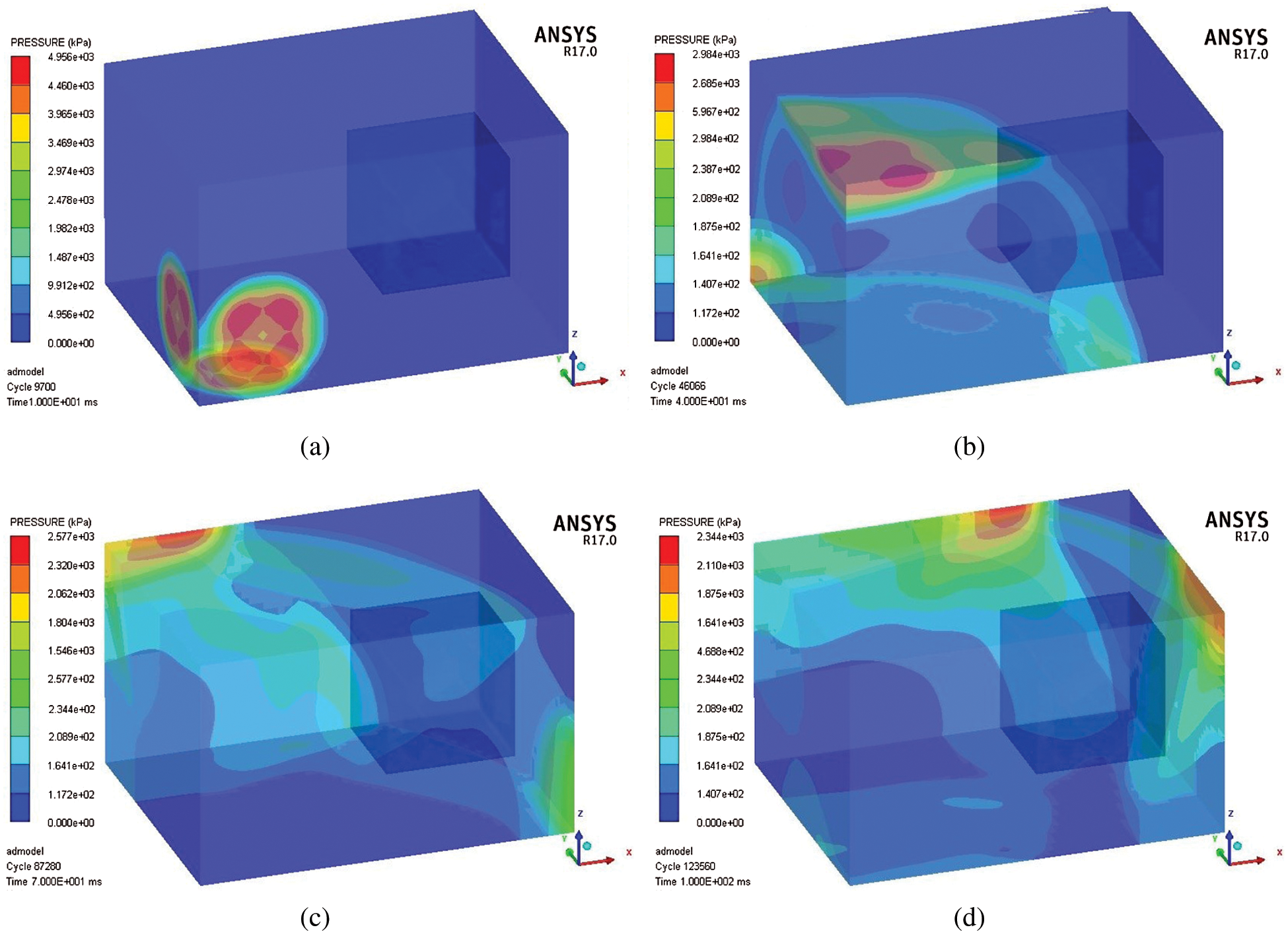
Figure 4: The pressure map in a single room (a) The pressure map in a single room at 10 ms (b) The pressure map in a single room at 40 ms (c) The pressure map in a single room at 70 ms (d) The pressure map in a single room at 100 ms
It can be observed from Fig. 4 that after TNT is detonated, high pressure is generated. The maximum pressure in a single room is as high as 495.6 KPa at 10 ms. After the explosion, the explosion shock wave first spreads around the source of the explosion, and then propagated a little further away until it reaches the outer surface of the rescue capsule’s cabin and the walls in a single room.
Several Gaussian points from the walls in a single room were chosen to observe the pressure variation of the Gaussian points during the entire explosion process. The results are shown in Fig. 5.
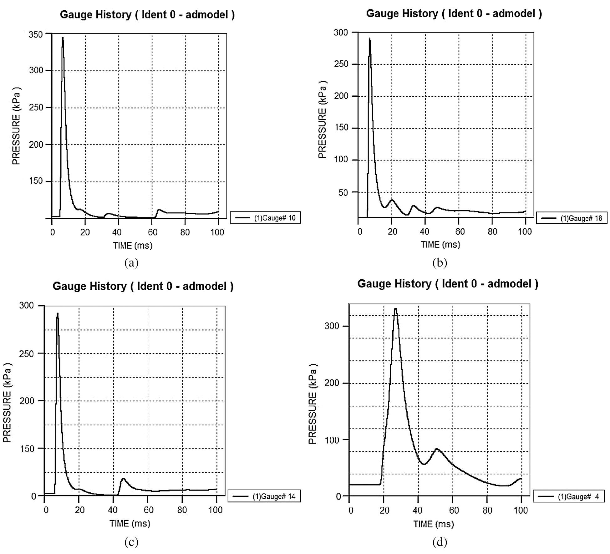
Figure 5: The pressure variation curves of some points on the wall in a single room (a) The pressure variation curve of 10# (b) The pressure variation curve of 18# (c) The pressure variation curve of 14# (d) The pressure variation curve of 4#
Fig. 5 is the pressure variation curve of the Gaussian point on the wall of the single room, 10# is the center of the left wall, 18# is the center of the front wall, 14# is the center of the upper wall, and 4# is the center of the back wall. It can be seen from Fig. 5 that in a single room the pressure variation of the shock waves reaching the Gaussian points on the walls are basically similar. It can be inferred that the closer a point is to the source of the explosion, the greater the peak pressure of the shock wave is (the maximum value of the pressure was found to be 350 KPa). The further it is from the source, the smaller the peak pressure of the shock wave is (the minimum value of the pressure was found to be 300 KPa). With the increase of time, the peak pressure of the shock wave is first transmitted to 10# (the center of the left wall) near the explosion source, then to 18 # (the center of the front wall), and then to 14 # (the center of the upper wall), and finally to 4 # (the center of the rear wall) far away from the explosion source. As time progresses, the explosion shock wave enters the depressurising stage, and the degree of oscillation of the shock wave also decreases accordingly.
In “ANSYS SpaceClaim,” the honeycomb cabin was built.
The materials used for the cabin in this paper are steel plates, Young’s Modulus is 206 GPa, yield strength is 800 Mpa, tensile strength is 1100 Mpa, and Poisson’s Ratio is 0.45.
Based on the characteristics of the cabin and the type of the solver selected, the chosen meshing method was “Hex Dominant.”
5.1.4 Apply Boundary Conditions
According to the method of numerical simulation of the dynamic response of the mine-used lifesaving cabin under impact loading studied by scholars, the applied loading conditions of the rescue capsule are simplified in this paper [31]. Based on the analysis results of the shock wave in Section 4.4, the shock wave was simplified into a triangular shock wave. In the “Transient Structural,” the simplified triangular shock wave was applied to the cabin. Since the blast load does not exceed 0.4 MPa, the peak pressure can be set to 0.4 MPa. The peak time of the shock wave is 60 ms, and the decaying-oscillation phase is from 60 ms to 400 ms. The applied explosion shock wave is shown in Fig. 6.
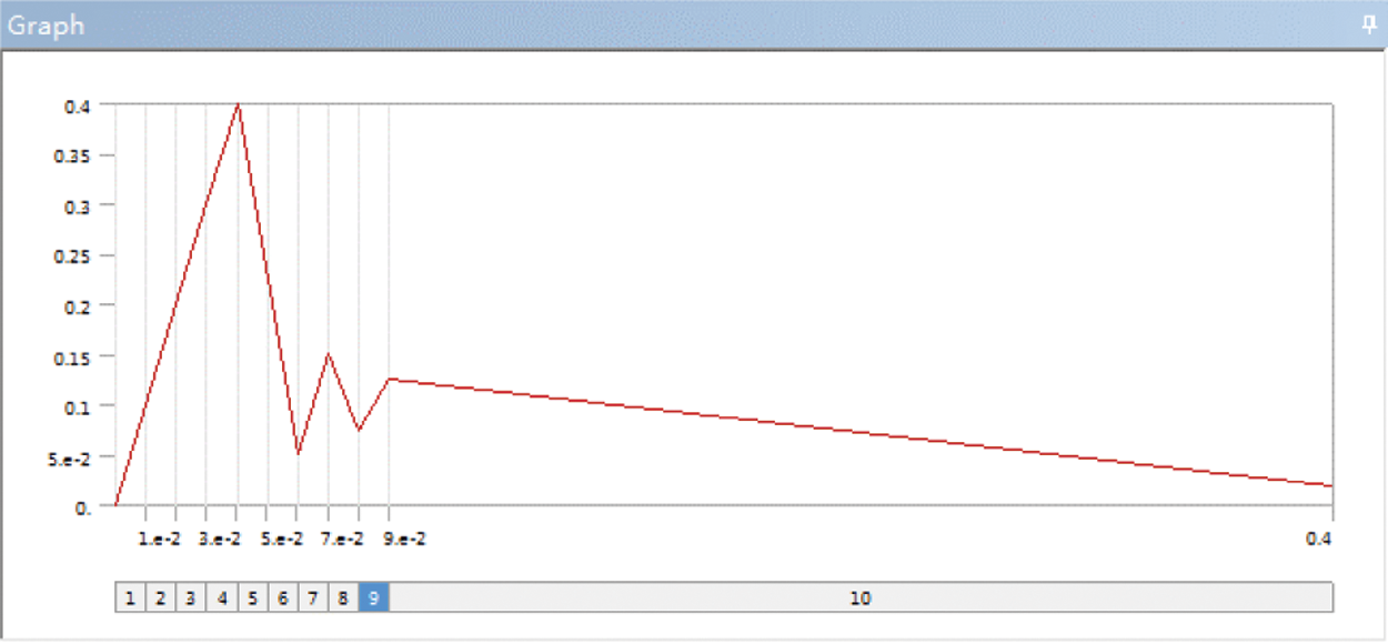
Figure 6: The applied explosion shock wave
The dynamic response of the rescue capsule under the blast load is calculated, and the stress map of the cabin at each moment is obtained as shown in Fig. 7.
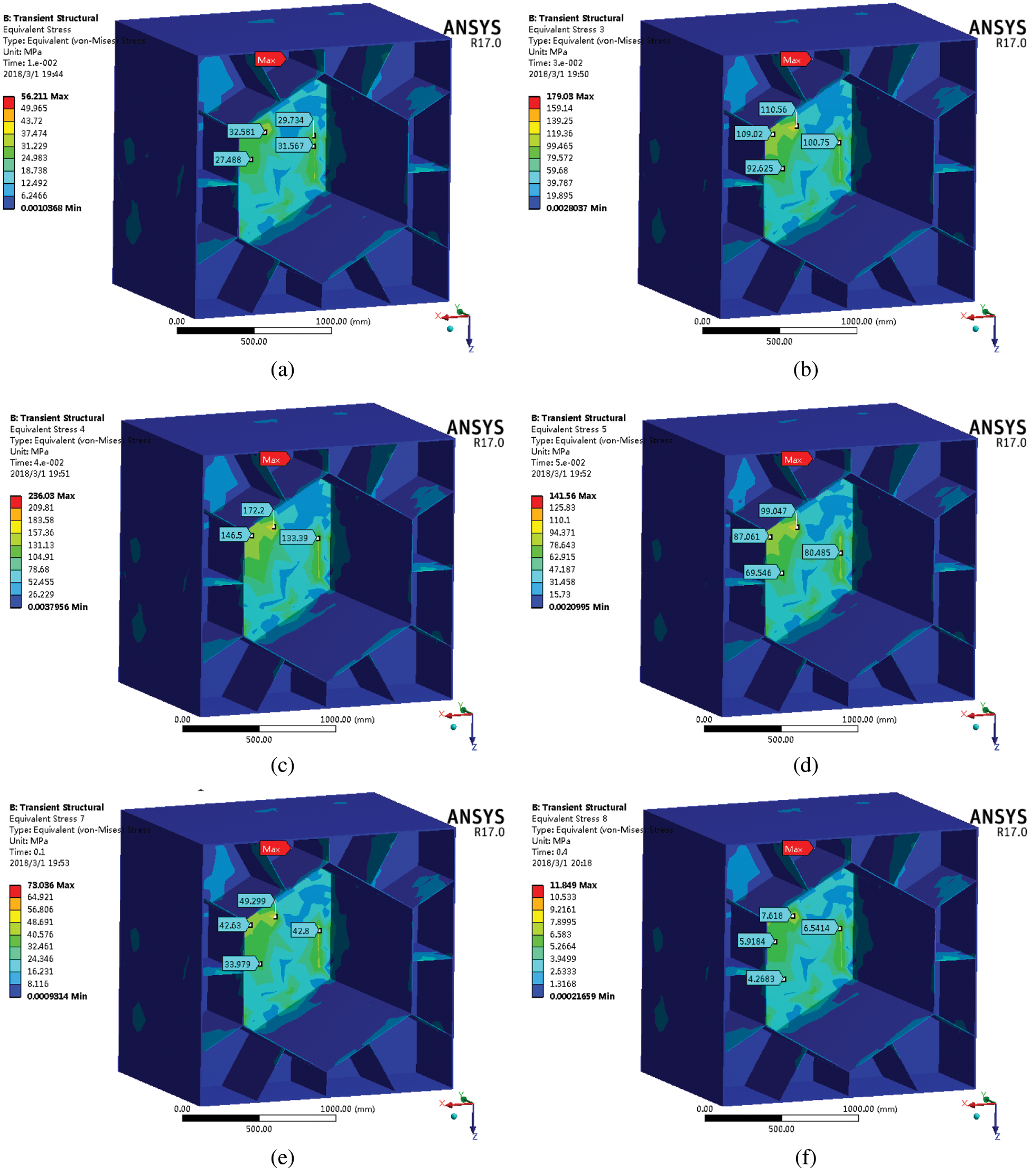
Figure 7: The stress map of the cabin at different times (a) The stress map of the cabin at 10 ms (b) The stress map of the cabin at 30 ms (c) The stress map of the cabin at 40 ms (d) The stress map of the cabin at 50 ms (e) The stress map of the cabin at 100 ms (f) The stress map of the cabin at 400 ms
The stress distribution of the honeycomb-like cabin at each moment under the blast load can be inferred from Fig. 7. During the changes of the blast load, the place where the stress concentration of the honeycomb-like cabin is always mainly on the rear cover of the cabin, and the maximum stress is always concentrated on the connection between the rear cover of the cabin and the inner cabin. At 40 ms, the cabin is subjected to the greatest stress, and its maximum stress value is 236.03 MPa. Since the yield strength of the materials used in the cabin is 800 MPa, the maximum stress on the cabin is within the range of the yield strength of the materials used. Therefore, the cabin meets the strength requirements.
In addition to the stress map of the cabin, the total deformation diagram of the cabin at various times can also be obtained as shown in Fig. 8.
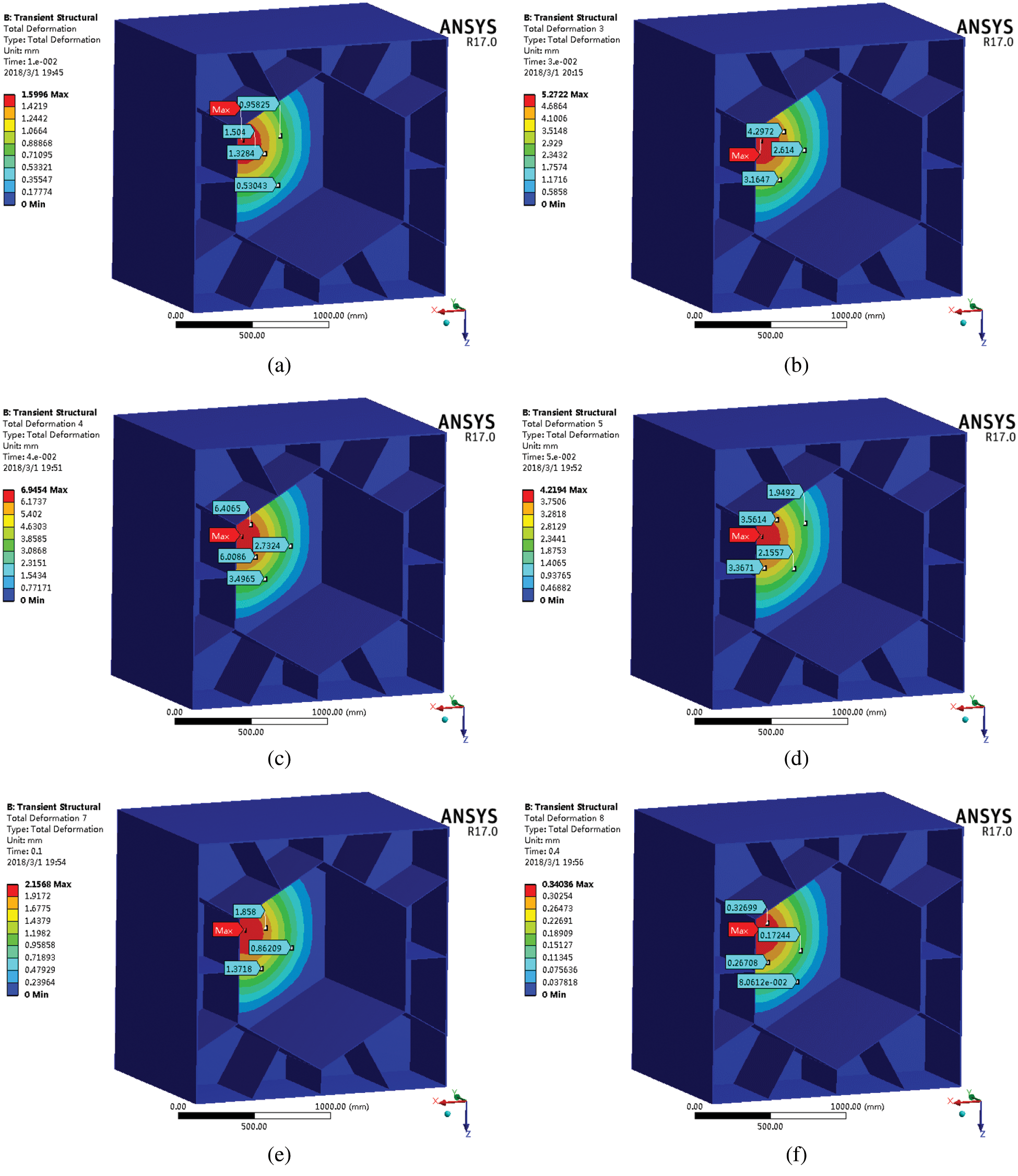
Figure 8: The total deformation diagram of the cabin at different times (a) The deformation diagram of the cabin at 10 ms (b) The deformation diagram of the cabin at 30 ms (c) The deformation diagram of the cabin at 40 ms (d) The deformation diagram of the cabin at 50 ms (e) The deformation diagram of the cabin at 100 ms (f) The deformation diagram of the cabin at 400 ms
Under the effect of the blast load, the total deformation distribution of the honeycomb-like cabin at different times can be seen in Fig. 8. During the changes of the blast load, the deformation of the honeycomb-like cabin is mainly on the rear cover of the cabin, and the maximum deformation is always concentrated at the center of the rear cover of the cabin. The deformation of the cabin reaches its maximum at 40 ms, and its maximum deformation value is 6.9454 mm. This shows that under the effect of the blast load, the rear cover of the cabin is the weakest position for the whole device. Because the maximum deformation value is within the tolerance range of the design, the honeycomb-like cabin meets the deformation requirements. In the future, the thickness of the rear cover may be increased or ribs may be added to the rear cover to further increase the reliability of the rescue capsule.
6 Thermal Protection Performance Analyses
Considering the location of a fire source has an effect on the temperature changes in the rescue capsule, this paper conducts a transient thermal analysis for two cases: the fire source is close to the rescue capsule and the fire source is far from the rescue capsule.
6.1 Basics of Transient Thermal Analysis
Referring to the existing research on the thermal protection of mine-used lifesaving cabins [32,33], this paper adopts a transient thermal analysis of the rescue capsule. ANSYS Workbench 17.0 can perform two types of the thermal analysis: steady-state and transient.
The general equation of the transient thermal analysis is as follows:
6.2 Model for Transient Thermal Analysis
Based on the study of the model for transient thermal analysis of the existing mine-used lifesaving cabin, the cabin structure of the rescue capsule is simplified, and the model for it is created in SpaceClaim. Fig. 9 shows the model for the transient thermal analysis of the cabin.
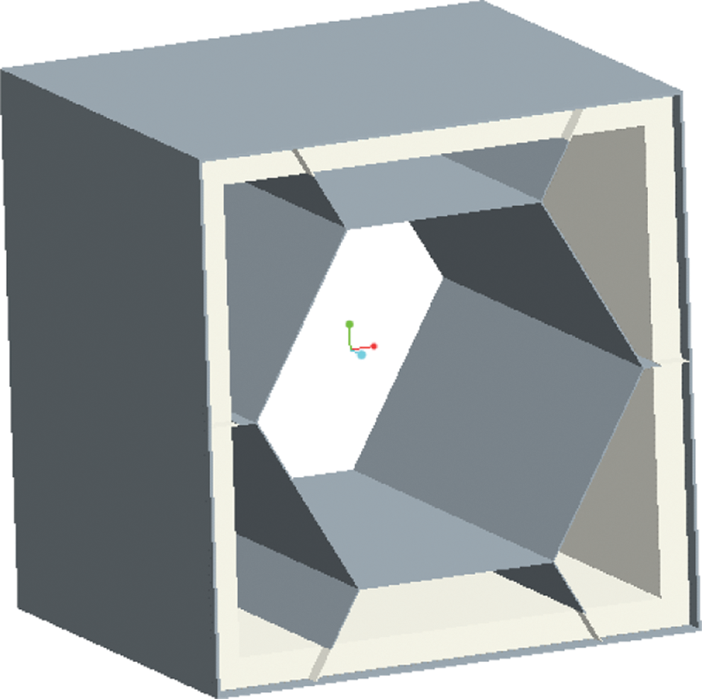
Figure 9: The model for transient thermal analysis of the cabin
6.3 Thermal Analysis of the Cabin Structure away from the Fire Source
The simplified rescue capsule model is imported into the “Transient Thermal” module in ANSYS Workbench 17.0. Firstly, the material properties are added to the cabin model. Then, the cabin is meshed, and finally the parameters are set such as the “Number of Steps” and “Step End Time” in the “Details of Analysis Settings” dialog. The material properties of the cabin are shown in Tab. 1.
6.3.2 Apply Boundary Conditions
The temperature rise curve of the rescue capsule is as follows. At t = 0 s, the room temperature of 25°C is applied to the outer surface of the rescue capsule. From 0 to 400 s, the temperature rises from 25°C to 500°C. At 400 s, the temperature reaches a stable level of 500°C. From 400 to 1000 s, the temperature remains unchanged at 500°C. The “Step End Time” is 1000 s.
After the boundary conditions are applied, the model can be analyzed and solved. After the model is solved, the temperature map and the temperature variation curve of each layer of the cabin at various times are obtained. The temperatures for each layer of the cabin are shown in Figs. 10–12, respectively.
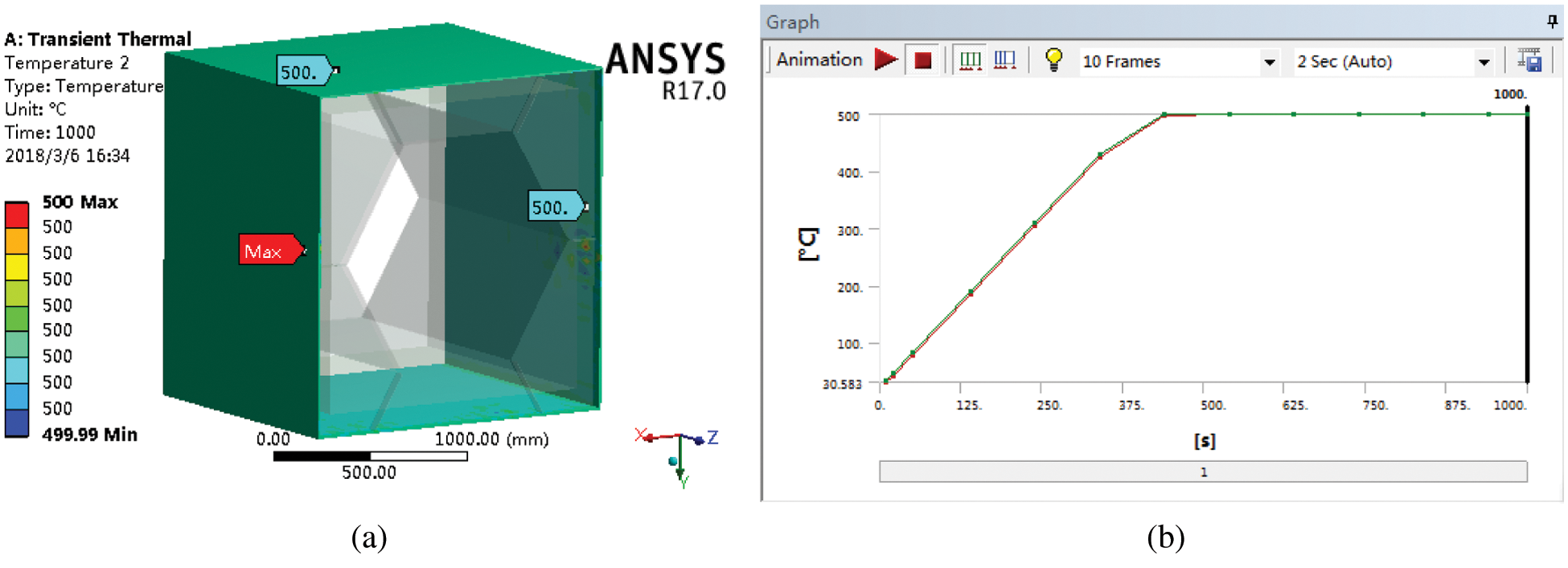
Figure 10: The temperatures of the outer layer of the cabin (a) The temperature map of the outer layer of the cabin at 1000 s (b) The temperature variation curve of the outer layer of the cabin
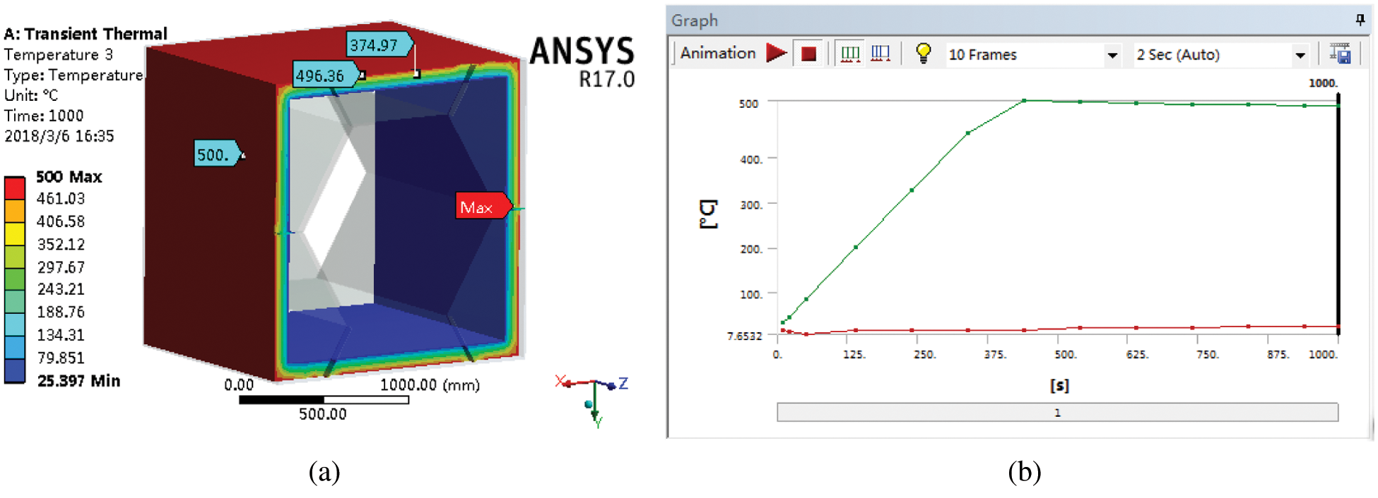
Figure 11: The temperatures of the thermal insulation layer of the cabin (a) The temperature map of the thermal insulation layer of the cabin at 1000 s (b) The temperature variation curve of the thermal insulation layer of the cabin
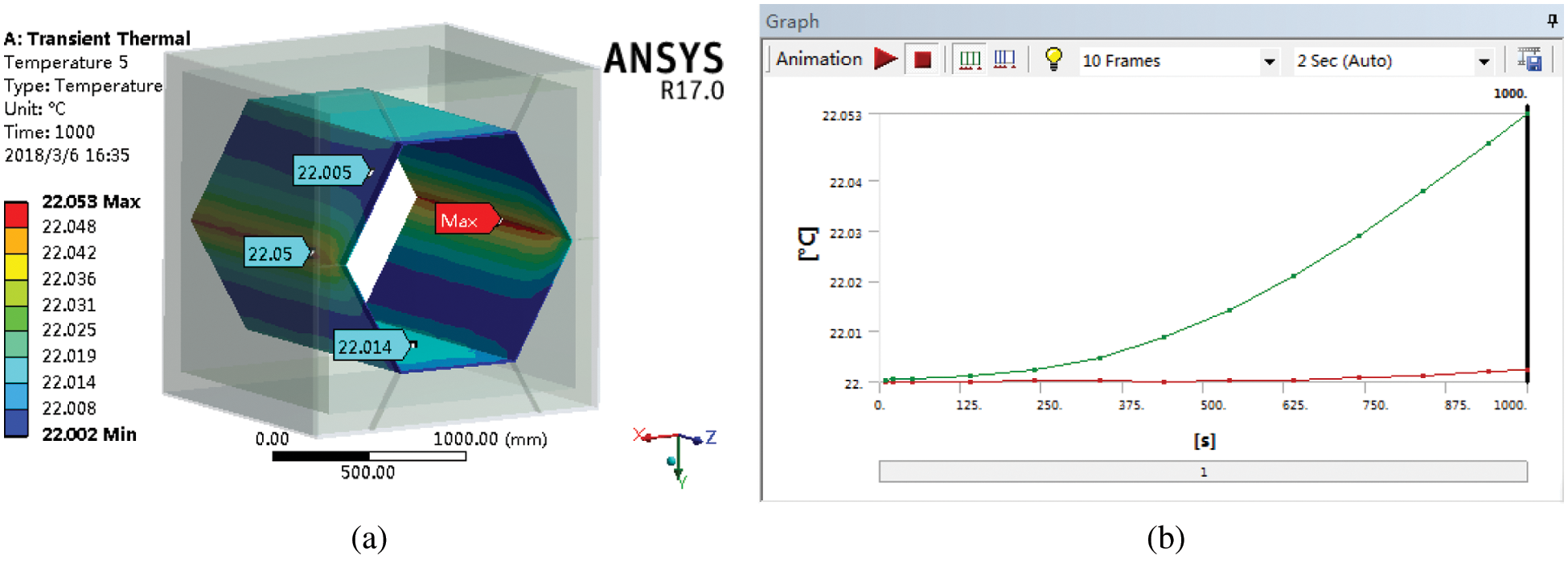
Figure 12: The temperatures of the inner layer of the cabin (a) The temperature map of the inner layer of the cabin at 1000 s (b) The temperature variation curve of the inner layer of the cabin
It seen in Fig. 10 that the temperature of the outer layer of the honeycomb-like cabin is as high as 500°C, and the temperatures of the inside and outside of the outer layer of the cabin are almost the same. This is because the outer layer of the honeycomb-like cabin is directly exposed to the fire environment, and the outer layer of the honeycomb-like cabin is made of steel plates with high thermal conductivity.
It can be seen from Fig. 11 that the highest temperature of the thermal insulation layer of the honeycomb-like cabin occurs on its outer surface (500°C), and the lowest temperature of the thermal insulation layer occurs on its inner surface (25.397°C). The temperature difference between the inner and outer surfaces of the thermal insulation layer is nearly 475°C. This shows that the thermal insulation layer of the honeycomb-like cabin has a good thermal insulation effect and can effectively prevent the heat transfer.
It can be seen from Fig. 12 that the temperature of the inner layer of the honeycomb-like cabin is relatively low, only about 22°C, and the temperature of the inner and outer sides of the inner layer is almost the same. This is because the inner layer of the honeycomb-like cabin is located on the inside of the thermal insulation layer, the inner layer is not directly exposed to the fire environment, and the heat is effectively blocked by the thermal insulation layer. In summary, the results indicate that the thermal insulation layer of the honeycomb-like cabin has a good thermal insulation effect and can effectively prevent the heat transfer.
6.4 Thermal Analysis of the Cabin Structure near the Fire Source
When the location of the fire source is close to the rescue capsule, the parameter settings of the rescue capsule are the same as those set in Section 6.3.1.
6.4.2 Apply Boundary Conditions
The method for applying the boundary conditions to the rescue cabin is the same as this in Section 6.3.2, but the final temperature 500°C must be changed to 1000°C.
After the boundary conditions are applied, the model can be analyzed and solved. The temperatures of each layer of the cabin are shown in Figs. 13–15, respectively.
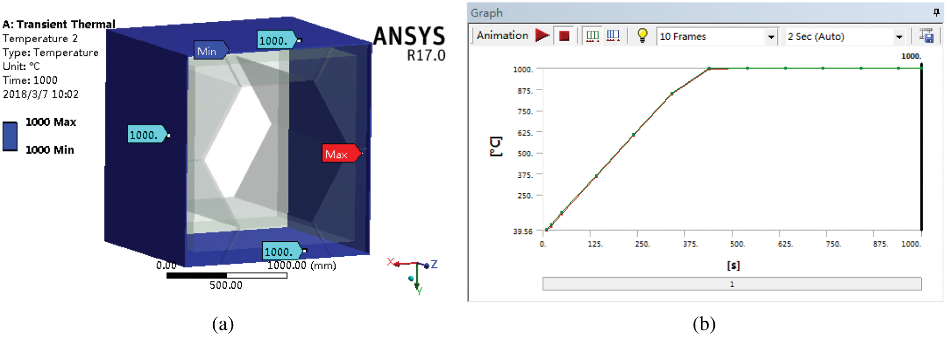
Figure 13: The temperatures of the outer layer of the cabin (a) The temperature map of the outer layer of the cabin at 1000 s (b) The temperature variation curve of the outer layer of the cabin
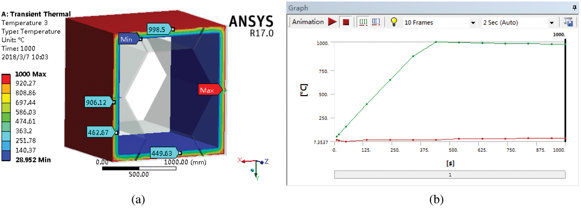
Figure 14: The temperatures of the thermal insulation layer of the cabin (a) The temperature map of the thermal insulation layer of the cabin at 1000 s (b) The temperature variation curve of the thermal insulation layer of the cabin
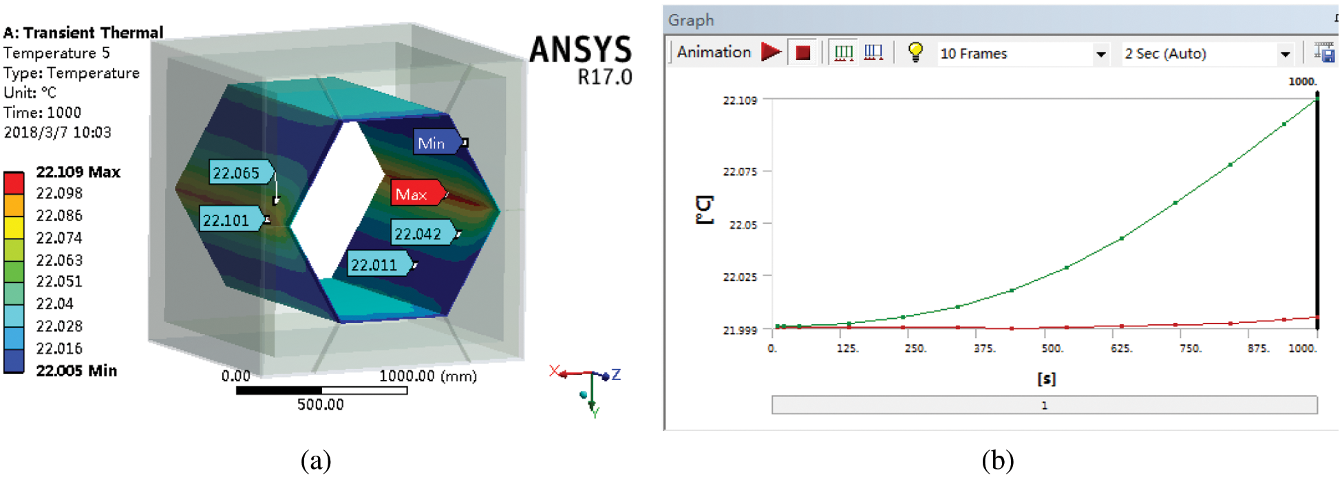
Figure 15: The temperatures of the inner layer of the cabin (a) The temperature map of the inner layer of the cabin at 1000 s (b) The temperature variation curve of the inner layer of the cabin
It can be seen in Fig. 13 that the temperature of the outer layer of the honeycomb-like cabin is as high as 1000°C, and the temperatures of the inside and outside of the outer layer of the cabin are almost the same. It can be seen in Fig. 14 that the highest temperature of the thermal insulation layer of the honeycomb-like cabin occurs on its outer surface (1000°C), and the lowest temperature of the thermal insulation layer occurs on its inner surface (28.952°C). It can be seen in Fig. 15 that the temperature of the inner layer of the honeycomb-like cabin is relatively low, only about 22°C, and the temperatures of the inner and outer sides of the inner layer are almost the same.
In summary, through the transient thermal analysis of the rescue capsule’s cabin under two different boundary conditions the following results are obtained. When the temperatures of the applied boundary conditions are 500°C and 1000°C, the temperatures of the inner layer of the cabin are only 22.053°C and 22.109°C, respectively. That is to say, when the temperature difference of the applied boundary conditions is 500°C, the temperature difference of the inner layer of the honeycomb-like cabin is very small. In summary, it shows that the thermal insulation layer of the honeycomb-like cabin has a good thermal insulation effect and can effectively prevent the heat transfer. The honeycomb-like cabin designed in this paper ensures that the temperature of the inner layer of the rescue capsule can increase the survival chances of Asylum seekers.
1. The honeycomb-like cabin designed in this paper has excellent resistance to pressure and space utilization. It meets the requirements of its resistance to pressure.
2. The thermal insulation layer designed in this paper is simple in structure and easy to disassemble and install. The selected thermal insulation material has a good thermal insulation effect and meets its thermal protection requirements.
3. The antiknock capabilities are carried out by using computer software. Based on the analysis of the antiknock capability of the honeycomb-like cabin, it is found that the stress concentration is located at the rear cover of the cabin and the deformation is at the center of the rear cover of the cabin. The honeycomb-like cabin meets the requirements of the antiknock capability.
4. The thermal protection analysis is carried out by using computer software. Through the transient thermal analysis of the honeycomb-like cabin under two boundary conditions, the heat transfer laws of each layer of the cabin are obtained, and the thermal protection performances of the honeycomb-like cabin are analyzed. When the temperature difference of the applied boundary conditions is 500°C, the temperature difference of the inner layer of the honeycomb-like cabin is very small. This shows that the thermal insulation layer of the honeycomb-like cabin has a good thermal insulation effect. It provides theoretical guidance for the improvement of the new cabins and the development of the similar devices.
Data Availability: The data used to support the findings of this study are available from the corresponding author upon request.
Funding Statement: This article was funded by the project (no. 51674149) supported by National Natural Science Foundation of China. The authors wish to acknowledge the support.
Conflicts of Interest: The authors declare that there are no conflicts of interest regarding the publication of this article.
1. G. W. Gao and L. H. Zhang, “Design principles of movable coal mine refuge chamber,” Journal of Safety Science and Technology, vol. 005, no. 004, pp. 162–164, 2009. [Google Scholar]
2. C. B. Ai, “Development status of national and foreign mine-used lifesaving cabin,” Chemical Defence on Ships, vol. 000, no. 006, pp. 5–8, 2010. [Google Scholar]
3. S. Wang, L. Z. Jin and J. Li, “The present states of overseas mine emergency refuge chamber technology,” Journal of Safety Science and Technology, vol. 006, no. 004, pp. 119–123, 2010. [Google Scholar]
4. Mine Safety and Health Administration, Labor, “Refuge alternatives for underground coal mines,” Federal Register, vol. 73, no. 251, pp. 80655–80700, 2008. [Google Scholar]
5. M. D. Mitchell, “Analysis of underground coal mine refuge shelters,” Ph.D. dissertation. West Virginia University, USA, 2008. [Google Scholar]
6. K. F. Zhang, M. Zhu, Y. J. Wang, E. J. Fu and W. Cartwright, “Underground mining intelligent response and rescue systems,” in Proceedings of the 6th International Conference on Mining Science and Technology, ICMST 2009, Xuzhou, China, pp. 1044–1053, 2009. [Google Scholar]
7. K. A. Margolis, C. Y. K. Westerman and K. M. Kowalski-Trakofler, “Underground mine refuge chamber expectations training: program development and evaluation,” Safety Science, vol. 49, no. 3, pp. 522–530, 2011. [Google Scholar]
8. J. L. Wang, “Design and research of domestic lifesaving cabin,” M.S. thesis. Qingdao University of Science and Technology, China, 2015. [Google Scholar]
9. K. G. Stricklin, “Mine safety and health administration,” Congressional Digest, vol. 87, no. 1, pp. 17, 2008. [Google Scholar]
10. Janovsky B., Selesovsky P., Horkel J. and Vejsa L., “Vented confined explosions in Stramberk experimental mine and AutoReaGas simulation,” Journal of Loss Prevention in the Process Industries, vol. 19, no. 2–3, pp. 280–287, 2006. [Google Scholar]
11. C. J. Gantes and N. G. Pnevmatikos, “Elastic–plastic response spectra for exponential blast loading,” International Journal of Impact Engineering, vol. 30, no. 3, pp. 323–343, 2004. [Google Scholar]
12. Jacinto A. C., Ambrosini R. D. and Danesi R. F., “Experimental and computational analysis of plates under air blast loading,” International Journal of Impact Engineering, vol. 25, no. 10, pp. 927–947, 2001. [Google Scholar]
13. N. Jacob, S. Chung Kim Yuen, G. N. Nurick, D. Bonorchis, S. A. Desai et al., “Scaling aspects of quadrangular plates subjected to localised blast loads-experiments and predictions,” International Journal of Impact Engineering, vol. 30, no. 8–9, pp. 1179–1208, 2004. [Google Scholar]
14. Y. C. Yu, “Simulation study on indoor gas leakage and explosion,” M.S. thesis. Harbin Institute of Technology, China, 2015. [Google Scholar]
15. E. X. Gao, C. X. Ding, S. L. Han, S. S. Meng and X. R. Zhang, “Distribution of flow parameters in coal mine gas explosion,” Blasting, vol. 30, no. 1, pp. 5–7+19, 2013. [Google Scholar]
16. H. Y. Dong, “Study on the whole structure design and antiknock ability of mine-used lifesaving cabin,” M.S. thesis. Taiyuan University of Technology, China, 2016. [Google Scholar]
17. X. Zhai, S. Wu, K. Wang, X. Chen and H. Li, “A novel design of rescue capsule considering the pressure characteristics and thermal dynamic response with thermomechanical coupling action subjected to gas explosion load,” Shock and Vibration, vol. 2017, no. 25, pp. 1–12, 2017. [Google Scholar]
18. G. Li, “The design & research on the new type of mobile mine capsule,” M.S. thesis. Qingdao University of Science &Technology, China, 2013. [Google Scholar]
19. M. Du, “Body research & test analysis on mobile refuge chamber,” M.S. thesis. Qingdao University of Science & Technology, China, 2013. [Google Scholar]
20. B. Bai, “Study on the explosive and thermal-shock resistance performance of refuge chamber,” M.S. thesis. Taiyuan University of Science & Technology, China, 2014. [Google Scholar]
21. X. R. Wang, H. Zhu, J. K. Gao and J. Jiao, “Insulating properties of mobile refuge chamber for coal mine,” Coal Mine Machinery, vol. 032, no. 003, pp. 61–62, 2011. [Google Scholar]
22. Y. Wang and H. R. Han, “Reference of the design experience of American rescue capsule,” Journal of Shanxi Datong University, vol. 35, no. 5, pp. 72–75, 2019. [Google Scholar]
23. State Administration of Work Safety, “Specifications for coal mine mobile refuge chambers,” 2011. [Online]. Available: http://www.mkaq.org/item/102063.aspx. [Google Scholar]
24. W. Shi, Y. Tan and Z. X. Cao, “Current study status and development tendency of the thermal insulation material,” Materials Reports, vol. 026, no. 001, pp. 344–347, 2012. [Google Scholar]
25. J. Song, Y. Liu, L. Chen, H. Huang, Z. Yue et al., “Current research status and development of thermal insulating materials in the world,” Materials Reports, vol. 24, no. z1, pp. 378–380+394, 2010. [Google Scholar]
26. Y. F. Fan and Z. P. Duan, “Experimental study on Johnson-Cook material model parameters,” Mechanics in Engineering, vol. 25, no. 5, pp. 40–43, 2003. [Google Scholar]
27. F. S. Cheng, “Pressure test of explosion shock wave in hermetic space and study on the distribution of overpressure of inner wall,” M.S. thesis. Nanjing university of science and technology, China, 2012. [Google Scholar]
28. Y. Wang, “Propagation law of explosion shock wave and overpressure load model in typical structure,” M.S. thesis. Tianjin University, China, 2008. [Google Scholar]
29. I. Freund, “Critical point explosions in two-dimensional wave fields,” Optics Communications, vol. 159, no. 1–3, pp. 99–117, 1999. [Google Scholar]
30. B. Luccioni, D. Ambrosini and R. Danesi, “Blast load assessment using hydrocodes,” Engineering Structures, vol. 28, no. 12, pp. 1736–1744, 2006. [Google Scholar]
31. Z. Q. Li, B. Bai, Q. H. Xie, Z. H. Wang and S. C. Cao, “Numerical simulation of the dynamic response of mine-used lifesaving cabin under impact loading,” Vibration and Shock, vol. 32, no. 16, pp. 151–156, 2013. [Google Scholar]
32. X. H. Wu, “Study on the temperature rise curve of the indoor based on the Regional Simulation,” M.S. thesis, Central South University, China, 2011. [Google Scholar]
33. H. F. Fang, S. R. Ge and M. Song, “Analysis on effect of heat bridge to heat transfer of refuge chamber’s shell,” Advanced Materials Research, vol. 211–212, pp. 624–628, 2011. [Google Scholar]
 | This work is licensed under a Creative Commons Attribution 4.0 International License, which permits unrestricted use, distribution, and reproduction in any medium, provided the original work is properly cited. |