DOI:10.32604/csse.2022.019872
| Computer Systems Science & Engineering DOI:10.32604/csse.2022.019872 | |
| Article |
Miniaturized Novel UWB Band-Notch Textile Antenna for Body Area Networks
1Department of Electrical and Computer Engineering, North South University, Bashundhara, Dhaka, 1229, Bangladesh
2Department of Computer Science, College of Computers and Information Technology, Taif University, Taif, 21944, Saudi Arabia
3School of Electronics & Electrical Engineering, Lovely Professional University, Punjab, India
4Department of Computer Engineering, College of Computers and Information Technology, Taif University, Taif, 21944, Saudi Arabia
*Corresponding Author: Mehedi Masud. Email: mmasud@tu.edu.sa
Received: 29 April 2021; Accepted: 15 June 2021
Abstract: This paper presents the design and analysis of a miniaturized and novel wearable ultra-wideband (UWB) band-notch textile antenna for Body Area Networks (BANs). The major goal of building the antenna for wearable applications with band notch in X-band is to reject the downlink band (7.25 to 7.75 GHz) of satellite communication in the UWB frequency ranges of 3.1–10.6 GHz to keep away from interference. Computer Simulation Technology (CST) TM Microwave Studio, which is user-friendly and reliable, was used to model and simulate the antenna. The radiating element of the antenna is designed on Jeans’ textile substrate, which has a relative permittivity of 1.7. The thickness of the jeans’ fabric substrate has been considered to be 1 mm. Return loss, gain, bandwidth, impedance, radiation, and total efficiency, and radiation patterns are presented and investigated. The antenna is simulated placed on the three layers of the human body model, and the on-body results are summarized in comparison with free space. Results and analysis indicate that this antenna has good band-notch characteristics in the frequency range of 7.25 GHz to 7.75 GHz. The parametric study varying the relative permittivity of Jeans’ fabric substrate of this antenna is also evaluated. In addition, effects on the antenna parameters of variation of ground plane size have been reported. The antenna is 25 mm × 16 mm × 1.07 mm in total volume. Results reveal that this antenna achieves the design goal and performs well both in free space and on the body.
Keywords: UWB; band notch; textile antenna; wearable antenna; on-body; BANs; jeans; X-band; CST
Recently, Wireless Body Area Networks (WBANs) systems are growing to be a prevalent study area due to their medical, real-time health monitoring, and entertainment applications. WBAN consists of numerous wireless sensor nodes dispersed throughout the human body that communicate with an on-body base unit to provide real-time patient monitoring. Ultra-wideband technology is a cutting-edge wireless communication system. UWB technology is thought to have a wide range of applications in short-range communications, wearable applications in sensor networks, body area networks, wireless positioning systems, IoT applications, biomedical imaging, and high data rate small range communications due to its low transmission power (−44.3 dBm), compact size, high data rate, and large bandwidth [1]. The UWB frequency range spans 3.1 to 10.6 GHz, according to the Federal Communications Commission (FCC) [2]. The problem is that other narrowband frequencies generate interference in the 3.1 to10.6 GHz frequency range. Therefore, the band-notch technique is essential. WiMAX, WLAN, and X band satellite communication channels interfere with UWB. As a result, in order to design an interference-free and power-efficient UWB communication system for Wireless, it is important to filter out these unneeded signals (BANs) [2,3].
In every wireless communication system, an antenna is one of the most important components. In Body Area Networks (BANs), there will be many sensor nodes over the human body surface for real-time health monitoring purposes where the antenna will be integrated with these sensors. The main problem is that the human body is made up of lossy tissues, and when the antenna is placed on it, the performance alters to that of free space operation. To make power-efficient wireless communications in BANs, researchers must investigate the impacts of the human body on antenna performance metrics such as return loss, gain, radiation efficiency, overall efficiency, bandwidth, and radiation pattern [1]. Otherwise, the UWB system may not work efficiently for BANs. A perfect antenna design gives relaxation to system designers. Researchers recently focused on designing a suitable wearable ultra-wideband antenna for efficient communication in BANs [4–7]. The modeling and categorization of UWB on-body radio channels for wireless body area networks have been provided in [8–11]. In [12–14], subject-specific UWB on-body propagation and radio channel characterization have been investigated. In the open literature, ultra-wideband band notch antennas have been described [3,15–25]. For the integration of ultra-wideband band notch characteristics, different authors have used different techniques on antenna structure. In [3,19,22,23] UWB antennas for X-band downlink satellite communication systems (7.25–7.75 GHz), a band elimination strategy has been utilized. Other authors reported band rejection at WLAN and WiMAX [14,16,18,20,21]. There has yet to be a breakthrough in the development of UWB wearable band notch antennas for BANs in healthcare applications. Several papers reported band-notch antennas for wireless communications, and few have been reported for WBAN. The majority of UWB band-notch antenna designs, on the other hand, have been focused on various substrates. Various authors showed antennas that were larger, which would not be suited for wearable applications. In WBANs scenarios, an antenna will be attached with the sensor system on the clothes of the human body. In this case, a textile-based wearable band-notch antenna could be a good option. However, there is a very limited study about the compact wearable UWB band-notch antenna in the open literature. According to knowledge, jeans’ textile-based compact wearable UWB antenna with the band rejection of X-band downlink satellite communication systems (7.25–7.75 GHz) has not been reported in any literature of the author in this paper.
The construction and analysis of a new and very tiny Jeans’ textile-based band notch, UWB wearable antenna for Body Area Networks (BANs) for real-time health monitoring applications are discussed in this research. Free space and on-body results are compared and investigated. In addition, a parametric study was performed varying the antenna ground plane size and dielectric constants of the Jeans’ fabric.
The following is a breakdown of the paper’s structure: The antenna design is discussed in Section 2. The results, parametric research, and discussion are provided in Section 3. In section 4, the on-body performance of the antenna has been discussed, and finally, Section 5 concludes the paper.
2 Jean’s UWB Band Notch Antenna Design
Figs. 1a–1c demonstrates the proposed miniaturized UWB band notch antenna showing the antenna’s detail sizes of various components. In addition, it shows a detailed design of the front side and backside of the antenna. The antenna is modeled with (CST)TM software, which is user-friendly and reliable. Figs. 1d and 1e show the front and back views of the CST design antenna. The simulated results of the CST design are comparable with measurements [1,4,6,7].
Jean’s textile substrate has a relative permittivity of 1.7, where the antenna’s radiating element is designed. The height of the Jeans’ textile has been considered as 1 mm in this study. The UWB antenna needs to be compact for wearable cases due to its longer battery life and user-friendly, textile-based design, and band rejection capability in the UWB frequency ranges to avoid interference from narrowband signals. By considering these facts, this antenna has been designed to be very compact. It has a total length and width of 25 and 16 mm, respectively. The ground plane’s thickness and radiating element have been considered similar, and that is 0.035 mm. Perfect Electric Conductor (PEC)/Copper has been used as the proposed antenna’s radiating element and ground plane. The antenna’s overall height is 1.07 mm, which includes the ground plane and the radiating element. As can be seen from Figs. 1c and 1e, there is the partial ground plane on the backside of the antenna. Research shows that an antenna with a full ground plane is better and less sensitive to the human body [1]. But to get the ultra-wideband bandwidth and impedance matching, the full ground plane is not possible at the backside of the antenna. To acquire band-notch, a slit is inserted to the top of the antenna radiating element. At 7 GHz, the wavelength of the antenna is 42 mm. The antenna is considered to bean electrically small antenna because the size (length) of the antenna is smaller compared to the wavelength. The electrical size for the length of this antenna is
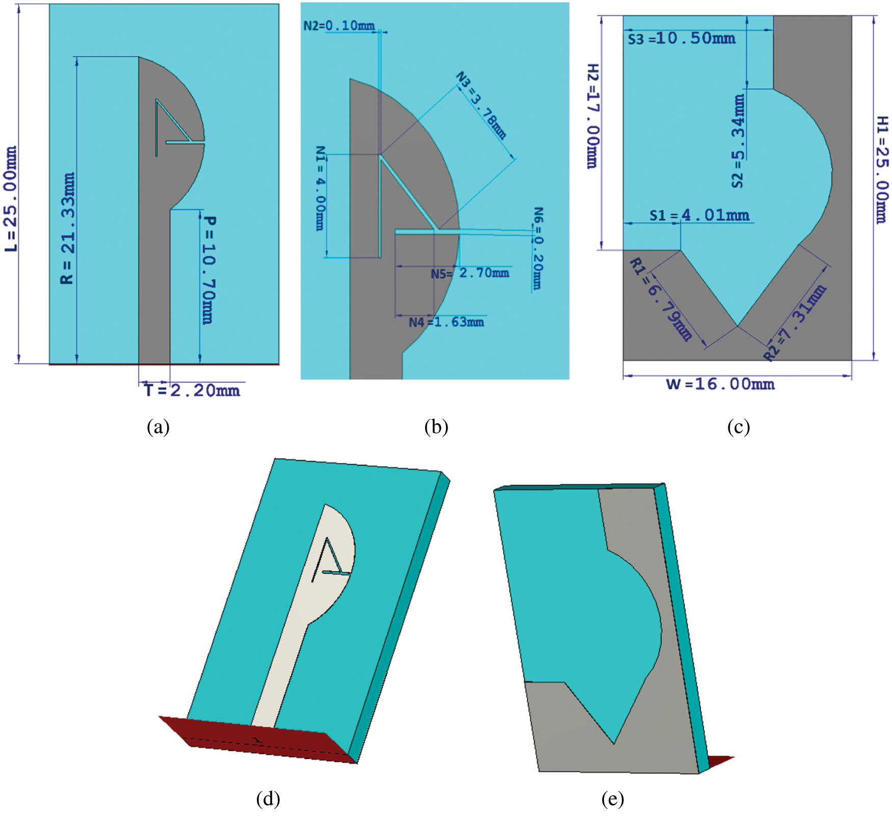
Figure 1: Novel and compact wearable UWB band notch textile antenna: (a) The front side (b) Details of the slit size in the front image. (c) Backside, demonstrating the size of the ground plane (d) Front view of CST design (e) Back view of CST design
This section has shown and discussed the return loss, bandwidth, gain, radiation efficiency, total efficiency, and radiation patterns. Then parametric study has been performed varying the antenna ground plane size and relative permittivity values of the antenna substrate. Finally, the antenna was simulated on three layers of the human body, and the results were shown and studied.
Fig. 2 depicts the antenna’s return loss response. The antenna has an excellent band notch in the frequency range of 7.25 to 7.75 GHz, according to the graph in Fig. 2. The antenna operates in the ultra-wideband entire frequency region (3.1 to 10.6 GHz). To reject X-band downlink satellite communication systems, it demonstrates band notch behaviors in the range of frequencies of 7.25 to 7.75 GHz. This was one of the goals of this paper, and the return loss result meets the goal. The return loss levels throughout the frequency spectrum of 7.25 to 7.75 GHz are well above −2 dB, allowing for interference-free communications in the UWB system for low-power BANs. Except for the band-notch frequency region, the antenna shows good return loss values in the range of operating frequencies. Tab. 1 lists the return loss values of the antenna at various frequencies.
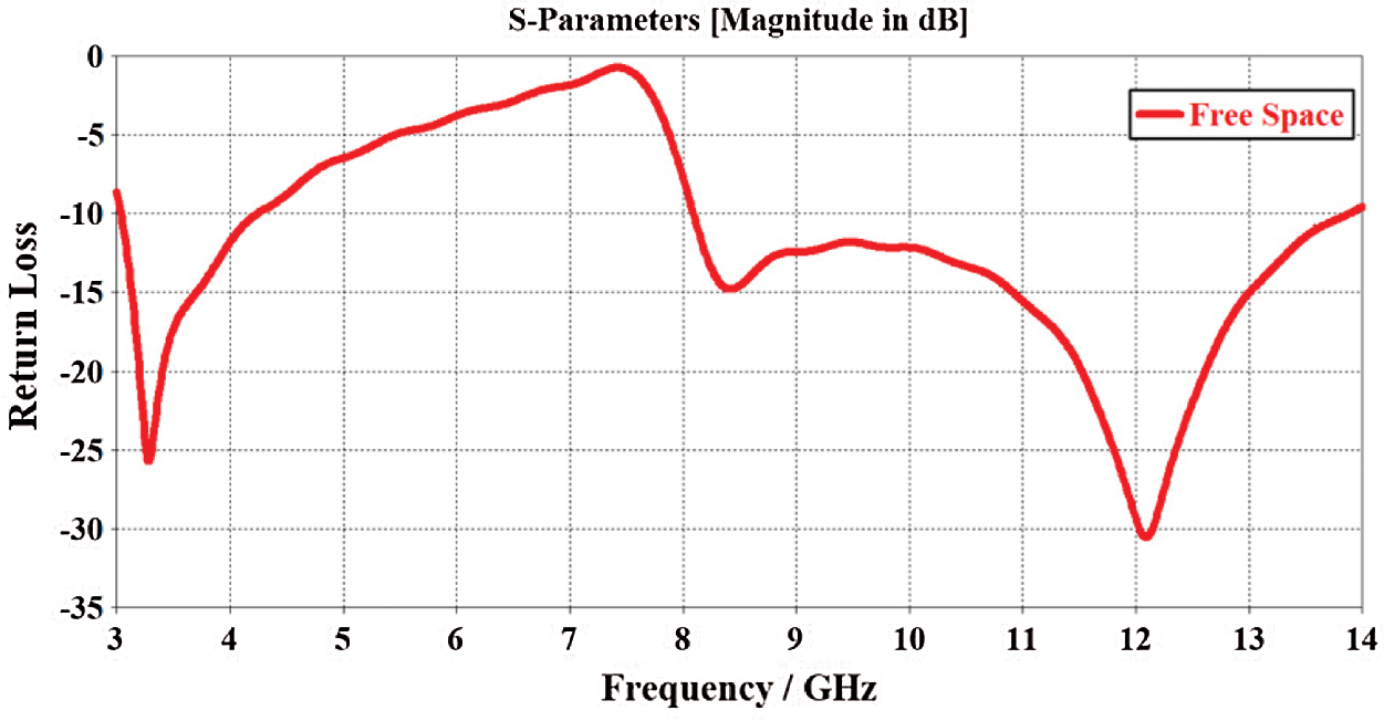
Figure 2: The antenna’s return loss response in open space
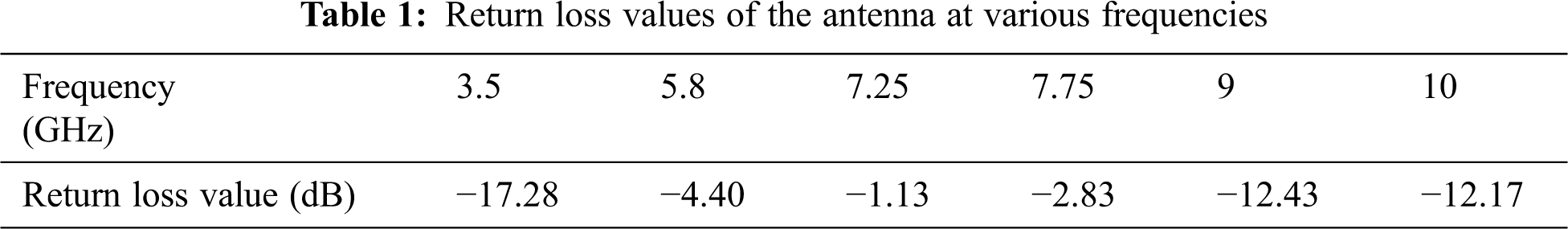
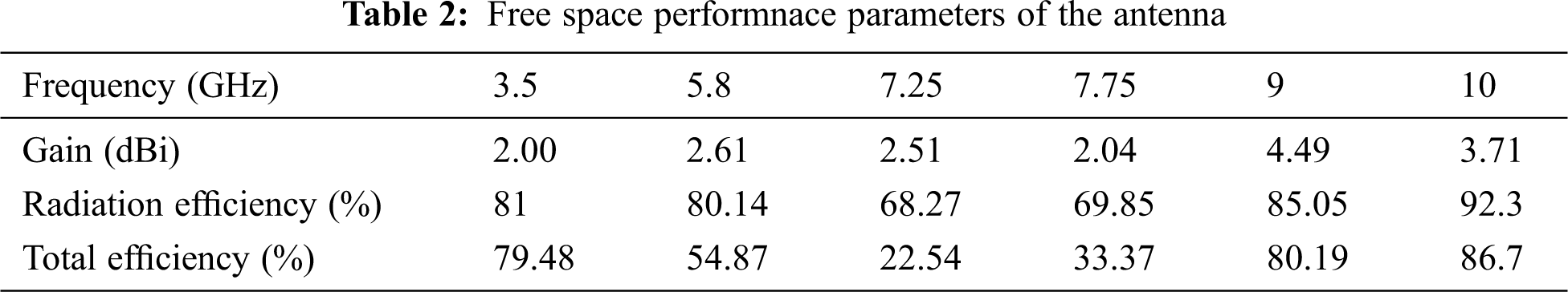
The antenna’s radiation efficiency and gain values are derived from the simulation results. Tab. 2lists the antenna’s gain, radiation efficiency, and total efficiency for six diverse frequencies. The gain and efficiency values are lower in the band-notch frequencies, and higher gain and efficiency are observed at the operational frequencies. For operating frequencies, the antenna gain is good enough for wearable applications for good power transmission. At 9 GHz, the highest gain (4.49 dB) is observed as compared to lower frequency bands of operations. It is noticed that at 9 and 10 GHz, the highest radiation efficiency is noticed.
3.3 Radiation Patterns in Free Space
From the simulation 3D radiation pattern, this antenna’s polar plot radiation patterns at six frequencies were extracted. The polar plot radiation patterns of the antennas at 3.5, 5.8, 7.25, 7.75, and 10 GHz are shown in Figs. 3a–3l. The H and E planes (azimuth and elevation planes, respectively) radiation patterns are displayed. From Fig. 3 indicates that the radiation patterns at 3.5 GHz of the H plane look omnidirectional, but in the E plane radiation patterns of the same frequency band, there is a null near the angle of 120 degrees. The polar plot radiation pattern at 5.8 GHz in the H plane seems to be like 3.5 GHz, but in the case of the E plane, the radiation pattern is slightly distorted between the angles of 150 to 240. The polar plot radiation patterns for 7.25 GHz look close to 5.8 GHz in both the H and E planes. The radiation patterns at 7.75 GHz at H and E planes look distorted. The radiation patterns look omnidirectional at higher frequencies like 9 and 10 GHz, but slight distortion is noticed for E plane radiation patterns.
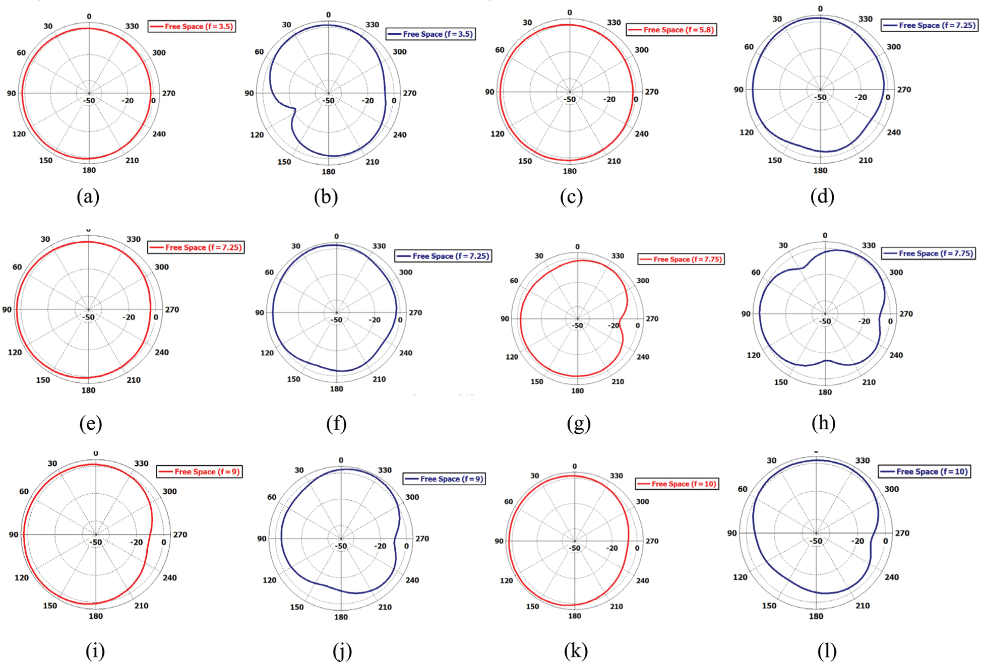
Figure 3: Free space H plane and E plane radiation patterns for six different frequencies: (a, b) Radiation patterns in the H and E planes at 3.5 GHz (c, d) Radiation patterns in the H and E planes at 5.8 GHz, (e, f) Radiation patterns in the H and E planes at 7.25 GHz, (g, h) Radiation patterns in the H and E planes, (i, j) Radiation patterns in the H and E planes at 9 GHz and (k, l) Radiation patterns in the H and E planes at 10 GHz
3.4 Antenna Ground Plane Size Variation
The antenna’s ground plane size was changed to see what effect it had on the return loss results. Fig. 4 illustrates the variation of the size of the ground plane. Fig. 4a is the original size of the antenna named as the proposed ground plane; see Fig. 1c. Fig. 4b is the reduced ground plane from the original design (proposed ground plane size). In Fig. 4c the ground plane has been increased by 1 mm from the original design. Fig. 5 demonstrates the return loss curves for the variation of the antenna ground plane size. To return loss responses for different ground plane sizes are demonstrated in different colors, see Fig. 5. The red curve represents the return loss for the initially proposed ground plane size, the blue curve represents the return loss when the ground plane size is reduced by 1 mm from the original design, and the green curve represents the return loss when the antenna ground plane is increased by one mm for the original design.
It can be seen in Fig. 5 that decreasing the ground plane dimension has an effect on the return loss responses. The lower frequency at −10 dB bandwidth shifts lower than the original design for increasing the dimension of the ground plane. The lower frequency band at −10 dB impedance shifted to the right when the dimension of the ground plane was reduced by 1 mm more than the proposed ground plane size. Changing the size of the ground plane, on the other hand, has no effect on the frequency of the band-notch regions, according to the research (see Fig. 5). It has been discovered that changing the ground plane size has no influence on the frequency range of band rejection or the band notch. In all cases, the band notch is nearly the same. The antenna’s impedance varies by changing the ground plane size at higher frequency, but the return loss remains below −10 very good dB bandwidth.
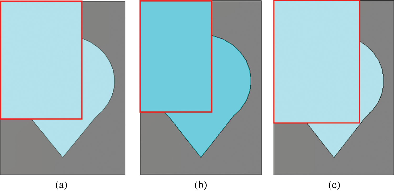
Figure 4: Variation in the ground plane’s size (a) Proposed ground plane (b) Reduced by 1 mm from proposed (c) Increased by 1 mm from proposed
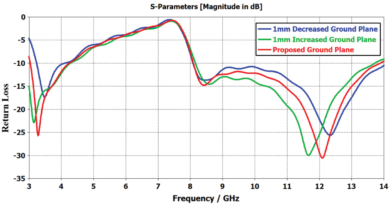
Figure 5: Return loss of the antenna for various ground plane sizes
3.5 Variation of Relative Permittivity
In this section, the antenna’s performance characteristics are investigated, varying the relative permittivity of the Jeans’ fabric to study the effects on the results. In this study, the Jeans’ textile’s height was fixed to 1 mm, the same as the original design, but the relative permittivity of the jeans substrate has been varied.
3.5.1 Return Loss Results for Variation of Permittivity
Fig. 7 illustrates the rerun loss curves of the antenna for various values of permittivity for the Jeans’ textile. The permittivity values are considered to be 1.7 (original design), 2.2, 4.4 of the Jeans’ fabric. Results expressed that verifying the permittivity values has many effects on the antenna return loss. An interesting result is noticed for the 4.4 value. For a relative permittivity value of 4.4, the band notch of the antenna shifted to 5 to 6 GHz regions. When the permittivity value is 1.7, the antenna has a band notch in the X band; on the other hand, when the permittivity value is 4.4, the band notch shifts to the WLAN band. When the relative permittivity value of the Jeans is set to 2.2, the band notch shifted to the lower band. It can be seen from Fig. 6. that varying the relative permittivity of the jeans substrate also affects the antenna’s impedance. The results concluded that varying the permittivity of Jeans’ textile affects the antenna return loss.
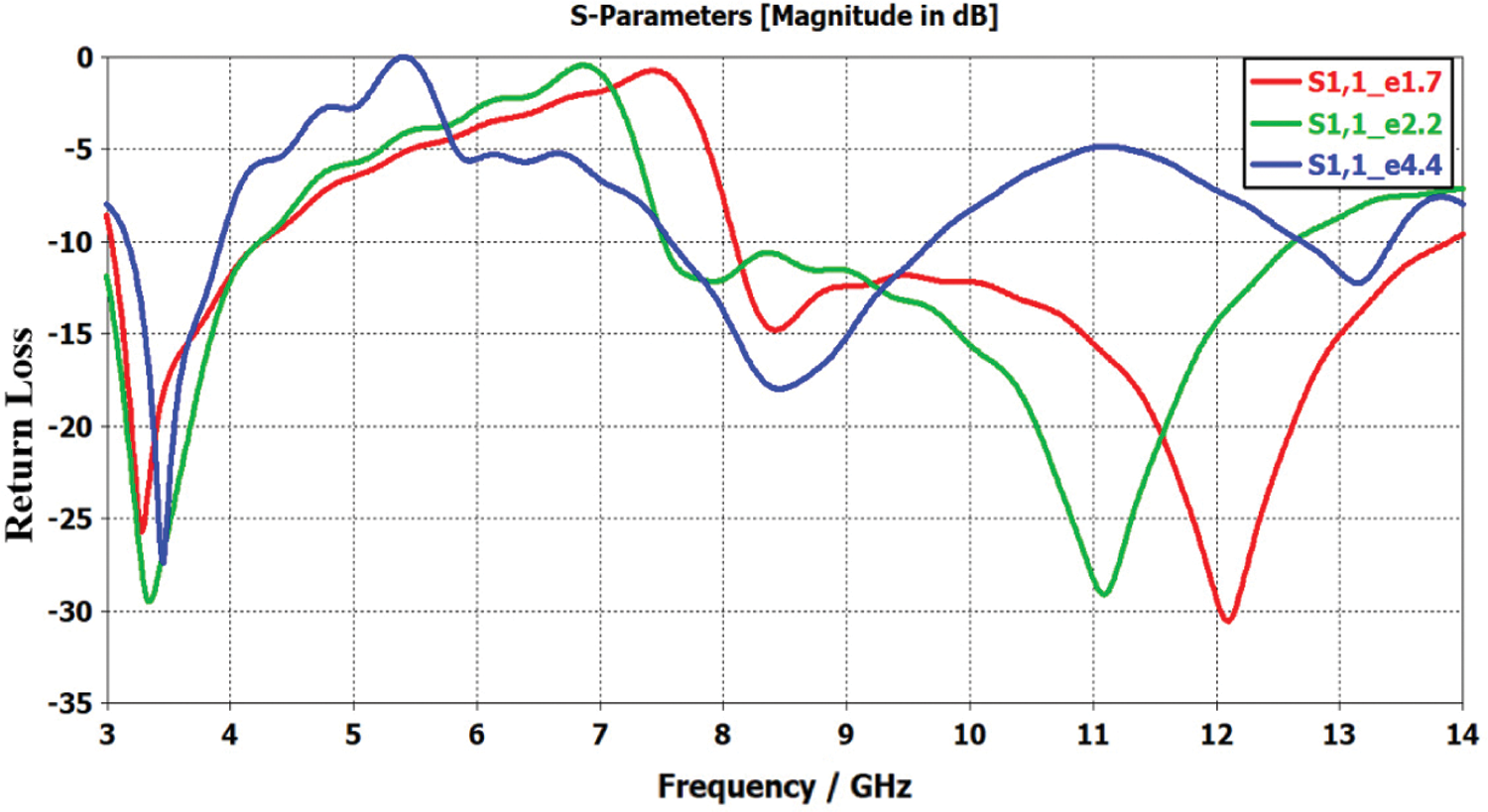
Figure 6: The antenna’s return loss responses as the dielectric constant of the jeans substrate changes
3.5.2 Gain for Variation of the Relative Permittivity (1.7, 2.2, 4.4) of Jeans’ Textile
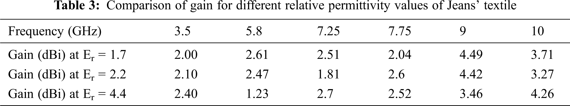
The gain of the antenna is investigated by varying the relative permittivity values of Jean’s fabric. In this case,Jeans’ textile’s relative permittivity is considered as 1.7, 2.2, and 4.4. Tab. 3 shows a comparison of gain for different relative permittivity values of Jeans’ textile.
Results and analysis show that changing the relative permittivity value of jeans textile affects the antenna gain. This happens due to the shift or antenna operating frequencies. At 9 GHz, the change of the relative permittivity value of the jeans textile has a very slight effect on the gain of 9 GHz because the gain values are very close to each other for different permittivity values. Not much effect of gain is that the variation is noticed for the change of relative permittivity value of jeans on a lower frequency band of 3.5 GHz. The antenna has a band notch from 7.25 to 7.75 GHz when the dielectric constant of the jeans is 1.7, but when the dielectric constant value is changed to 4.4, the band notch is noticed at the WLAN band; therefore the gain changes more. However, variation of permittivity value affects the gain of 5.8 and 7.25 GHz that is happened due to frequency shifting and impedance matching reasons.
3.5.3 Radiation Efficiency for Variation of Permittivity Value of Jeans’ Fabric
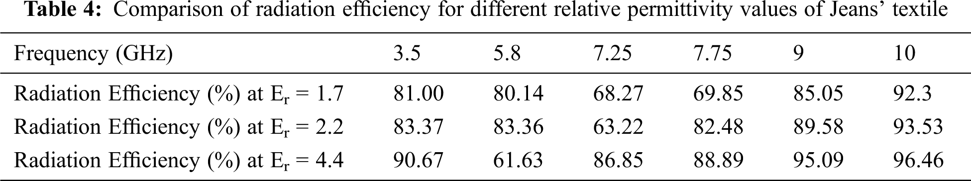
Tab. 4 compares radiation efficiency for different relative permittivity values of Jeans’ textile at different frequencies. Results show that variation of relative permittivity value affects the radiation efficiency of the antenna. It is noted that the effect is higher for 5.8, 7.25, and 7.75 GHz and less for 3.5, 9, and 10 GHz. In this study, the highest radiation efficiency (96.46%) is noticed at 9 GHz when the dielectric value of the jeans fabric is used as 4.4. At 5.8 GHz, the poor radiation efficiency (61.63%) is noticed when the jeans’ fabric’s permittivity value is set to 4.4. This is due to changing the permittivity value of jeans that shift the band notch to 5.8 GHz.
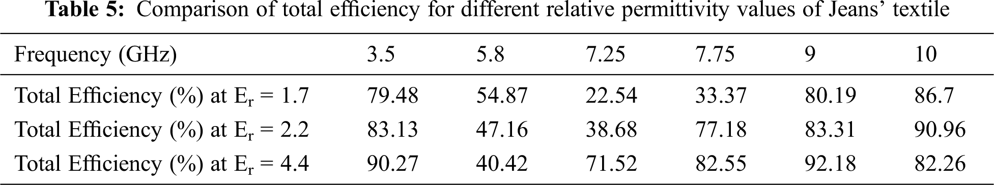
Tab. 5 compares total efficiency for different relative permittivity values of Jeans’ textile at different frequencies. It is observed from Tab. 5 that variation of relative permittivity value affects the radiation efficiency of the antenna. The effect is higher for 5.8, 7.25, and 7.75 GHz and lower for 3.5, 9, and 10 GHz when the dielectric permittivity of jeans changes the frequency of operation and band notch shift, which causes the variation of total efficiency of the antenna.
3.5.4 RadiationPatterns for Variation of Permittivity Values of Jeans’ Fabric
The effects of the variations of the dielectric constant of Jeans’ fabric on the radiation patterns of the antenna are also investigated. Figs. 7a–7l compares radiation patterns for various relative permittivity values of the antenna at 3.5, 5.8, 7.25, 7.75, 9 and 10 GHz. Radiation patterns are plotted based on elevation and azimuth planes. In Fig. 7, the radiation patterns for different dielectric permittivity are plotted, showing different colors. In Fig. 7, the red color shows the radiation pattern for the dielectric value of 1.7. The blue color shows the radiation pattern for the dielectric value of 4.4. The green color shows the radiation pattern for the dielectric value of 2.2.
At 3.5 and 5.8 GHz in the H plane due to variation of relative permittivity does not affect the radiation patterns. However, in the E plane, a slight variation of power level near the angle of 120 degrees is noticed. Changing the relative permittivity value of jeans textiles has a higher effect on band notch frequencies (7.25 and 7.75 GHz) in both planes. At 7.25 GHz in the H plane, the radiation patterns look similar to the dielectric values of 1.7 and 4.4, but there is a power level drop for the value of 2.2 in the same plane, and a small null is noticed at the angle of 270 degrees. At 7.25 GHz, in the E plane, the radiation patterns for the dielectric constant of 2.2 and 4.4 are nulls at different angles. The radiation patterns of the H plane at 9 and 10 GHz are nearly similar, but in the E plane, for different dielectric values of jeans substrate, the radiation patterns vary.
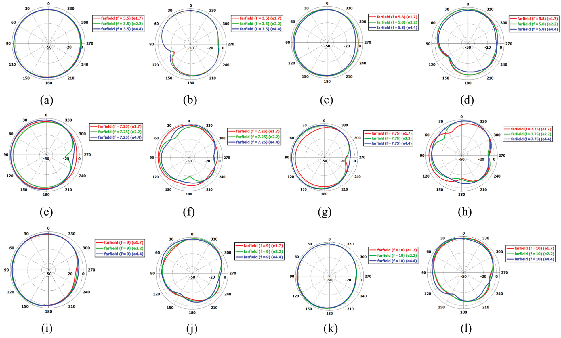
Figure 7: Comparison of radiation patterns for different dielectric constant values of the Jeans’ textile: (a, b) Radiation patterns in the H and E planes at 3.5 GHz (c, d) Radiation patterns in the H and E planes at 5.8 GHz, (e, f) Radiation patterns in the H and E planes at 7.25 GHz, (g, h) Radiation patterns in the H and E planes, (i, j) Radiation patterns in the H and E planes at 9 GHz and (k, l) Radiation patterns in the H and E planes at 10 GHz
4 Study of on-Body Performance
To test the antenna’s on-body performance, the on-body antenna parameters are examined and assessed in this part. Using the CST software, a three-layer human body model was created.
4.1 Three Layers Human Body Model
The three layers of the human body model are depicted in Figs. 8a and 8b, with the antenna on top of the skin layer. The skin (top layer), fate (middle layer), and muscle (bottom layer) are the three layers. The thickness of the skin layer, fat layer, and muscle layer is 2, 10, and 10 mm, respectively. Tab. 6 lists the height, width, and length of three human body tissues: skin, fat, a nd muscle. The dielectric properties of the human frequency dispersive body model are calculated from [26]. During CST simulations, the relative permittivity and loss tangent of the human body model layers where skin, fat & muscle formation are determined. The dielectric characteristics and tangent loss of skin, fat, and muscle are shown in Tab. 7. For this study, the gap between the antenna and the three-layer human body model was set to 4 mm; see Fig. 8.
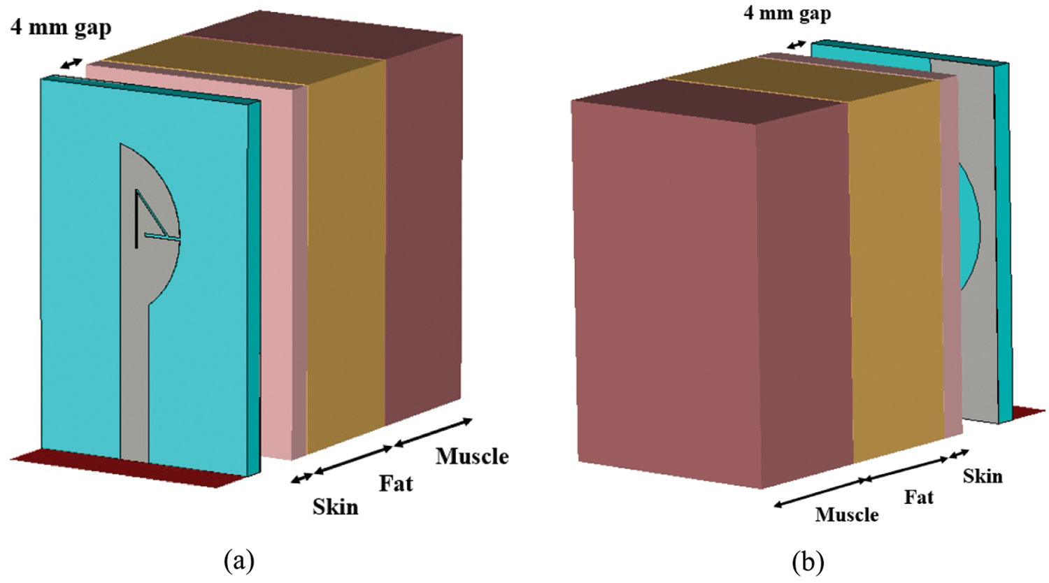
Figure 8: Three layers human body model (skin, fat and muscle) showing antenna on the top. (a) front view (b) Back view
4.2 Return Loss Responses (Free Space and On-body)
Comparison of free space and on-body return loss responses of the antenna are provided in Fig. 9. From Fig. 9, it is observed that when the antenna is put on the human body model, slight frequency detuning is noticed at the lower band; however, the band notch still remains in the same range, 7 to 7.85 GHz. A slight change of impedance is observed while placing the antenna on the human body outside the band of both frequencies. Free space and on-body return loss responses have nearly similar results.
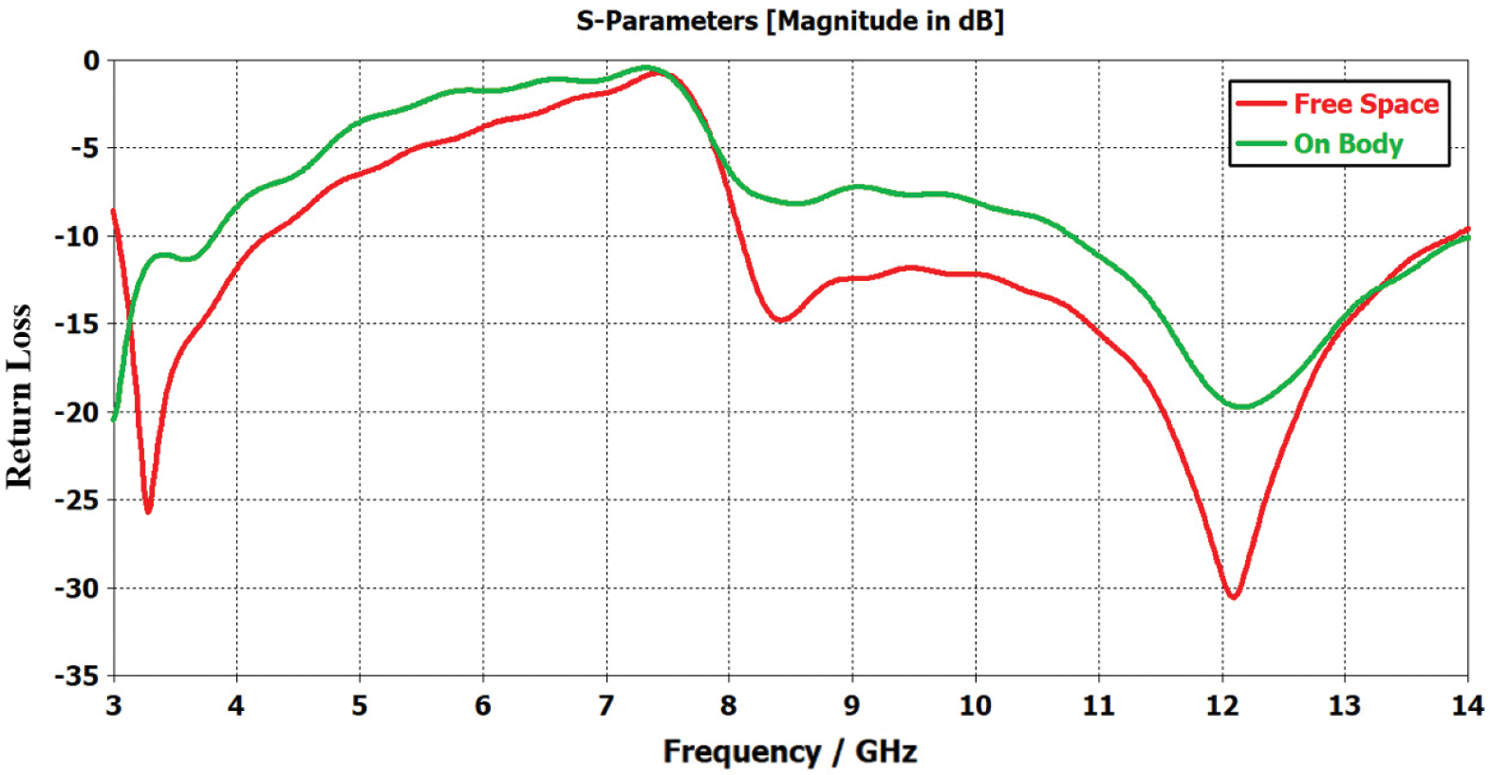
Figure 9: Comparison of free space and on-body return loss responses
4.3 Free Space and on-body Gain, and Efficiency
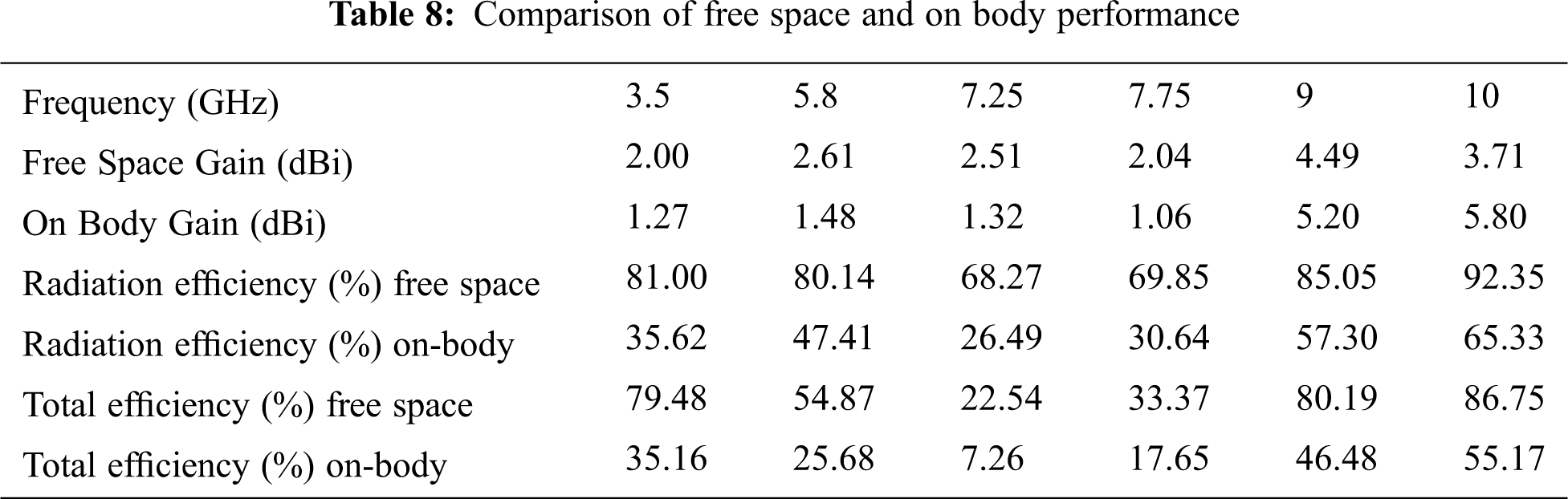
Tab. 8 shows a comparison of free space gain and radiation efficiency for the antenna at six frequencies. From Tab. 5, it is observed that once the antenna is put at a 4 mm gap on the human tissue model, a reduction of gain is noticed for 3.5, 5.8, 7.25, and 7.75 GHz; an increase of gain is noticed for 9 and 10 GHz. The lowest gain of 1.32 dB for 7.25 GHz and 1.06 dB is noticed for 7.85 GHz on the human body. This is due to the band notch at these frequencies. This antenna shows a maximum of 5.20 and 5.80 dB gain at 9 and 10 GHz on the body, respectively. This antenna shows very goodon the body gain, which is good for power-efficient on body communication with other body-mounted nodes in body area networks. Placing the antenna on the human body model shows that the antenna still shows a very good gain. This could be owing to the ground plane on the backside of the antenna, which acts as a barrier between the antenna and the human body, reducing the lossy tissue effects of the human body on the antenna parameters. Previous research has shown that as the distance between the antenna and the human body widens, the antenna’s performance approaches that of free space [1]. Therefore, if the antenna placement gap between the antenna and the body increases to 6 or 8 mm, the on-body results may improve further.
The radiation efficiency of the antenna is also studied, placing the antenna on the human body model. In this case, the same gap (4 mm) was considered between the antenna and the human body model. Tab. 8 provides a comparison of free space and on-body performance. When the antenna is positioned on the body, the radiation efficiencies decrease from free space for all frequencies. This is due to the absorption of the human lossy tissues. However, on the body, this antenna shows well on body radiation efficiencies. The greatest radiation efficiencies, 57.30% and 65.33% are noticed for the 9 and 10 GHz on the body, respectively. In the band, both frequencies, the radiation efficiencies are very low, which is expected. As compared to a higher frequency, the lower frequency bands have higher radiation efficiency reduction when the antenna is put on the body.
The total efficiency of this antenna is also investigated. The free space and on-body total efficiency are also provided in Tab. 8. The total efficiency of this antenna is also reduced when the antenna is put on the body. However, this antenna illustrates very good body total efficiency, although it is very compact in size. The highest on-body total efficiencies (46.48% and 55.15%) are noticed at 9 and 10 GHz, respectively. Like radiation efficiency on the human body model, this antenna shows the lowest total efficiencies in the band of both frequencies. The lowest total efficiency of 7.25% is noticed at 7.25 GHz.
4.4 On-Body Radiation Patterns
The on-body radiation patterns were also shown plane-wise as azimuth and elevation, corresponding to the H and E planes. Figs. 10a–10l provides free space and on-body polar plot radiation patterns of the antenna for various frequencies of H and E planes. Figs. 10a, 10c, 10e, 10g, 10i and 10k shows H plane while Figs. 10b, 10d, 10f, 10h, 10j and 10l E plane radiation patterns. Mostly for all frequencies, the on-body radiation patterns and free space in the H plane and E plane are nearly similar, but reducing power level compared with free space radiation patterns is noticed. Both free-space and on-body radiation patterns for band-notch frequencies look distorted in companion with the radiation patterns of other operating frequencies. It can be seen in Fig. 10 that the on-body radiation patterns have higher power levels than the free space radiation patterns in some cases. This may be due to the human body model. The radiation patterns, in some cases, more directive in direction than others. The human body is lossy tissues putting the antenna on the human body, the power level of the radiation patterns are reduced. It is noticed in most of the cases here in this study. On the other hand, the radiation pattern is less affected by human lossy tissues because of the ground plane on the backside of the antenna.
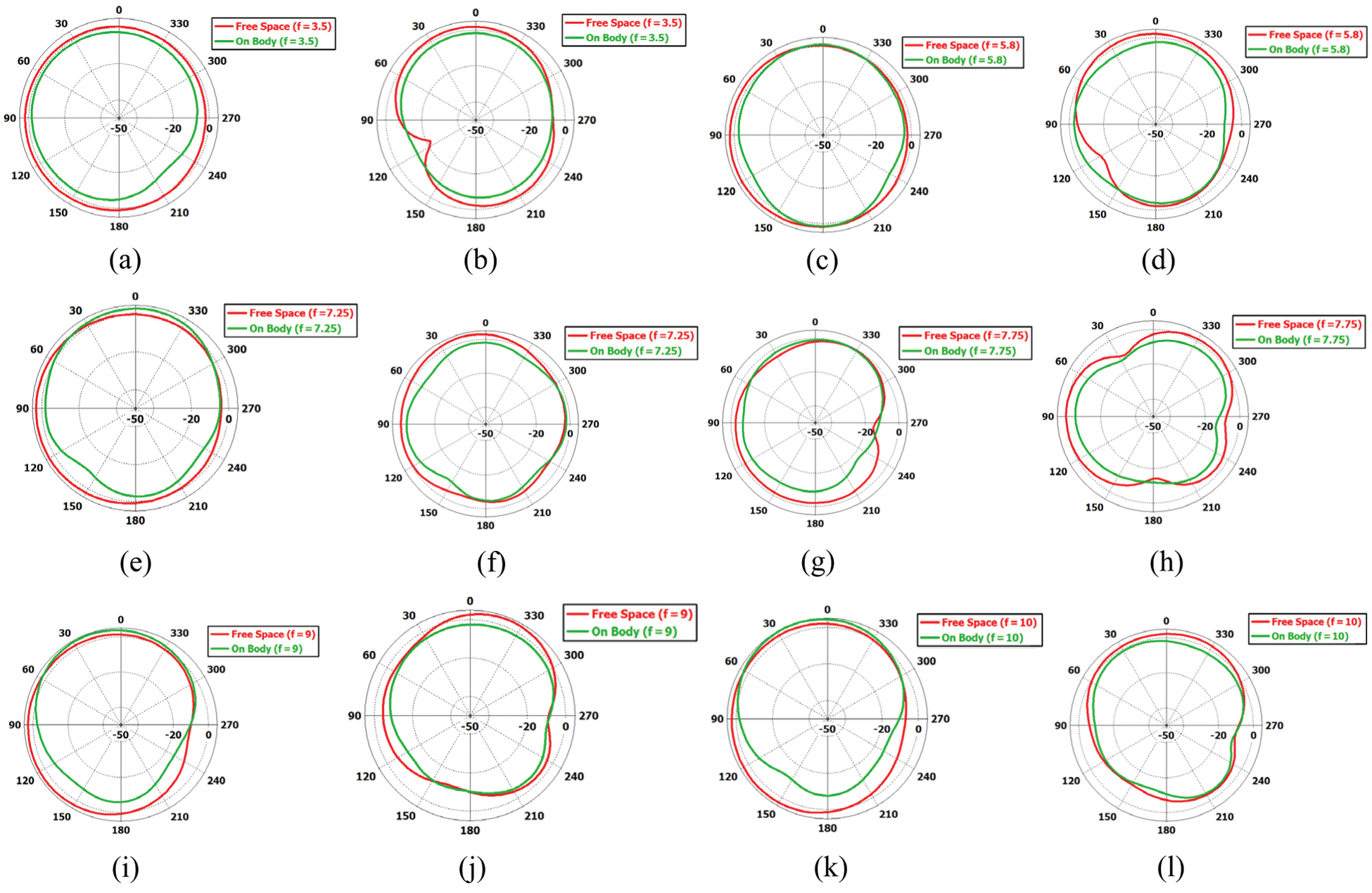
Figure 10: H and E planes free space and on-body radiation patterns for different frequencies
A new miniaturized wearable ultra-wideband band notch jeans’ textile-based antenna for Body Area Networks (BANs) is designed and presented. To avoid interference, the antenna operates in the ultra-wideband frequency bands of 3.1 to 10.6 GHz with band-notch capabilities in X-band to exclude the downlink band (7.25–7.75 GHz) of satellite communication. Antenna performance parameters are presented and investigated. Parametric study results of the variation of antenna ground plane size are demonstrated and analyzed. Results and analysis show that variation of ground plane size does not affect the band rejection frequency range or band notch; however, slight frequency shifting at a lower frequency range is observed.
The performance parameters of the antenna for different relative permittivity values of Jeans’ fabric are presented and investigated. Results show that variation of relative permittivity values of Jeans’ fabric has huge effects on the antenna performance parameters. Finally, the on-body performance parameters of the antenna are presented and analyzed. Results show that when the antenna is put on the body, the band notch remains in the same frequency range (7.25 to 7.75 GHz). The antenna performs very well even when it is put very close to the human body model at operating frequencies such as 3.5, 5.8, 9, and 10 GHz. The antenna shows very poor results at 7.25 and 7.85 GHz both in free space and on the human body model due to band notch characteristics, and that is expected. The antenna performs very well at other frequency bands of operation. This antenna shows a maximum of nearly 65.33% radiation efficiency, 55.17 total efficiencies, and 5.80 dB gain at 10 GHz when placed even very close (4 mm away) to the human body model. The antenna’s length, width, and height are 25, 16, and 1.07 mm, respectively. The antenna is electrically small at the center frequency of operation. The antenna was printed on Jeans’ fabric, and the total height of the antenna is considered to be 1.07 mm. Due to textile-based, this antenna will be a good choice for wearable applications. This UWB antenna will be appropriate for wearable applications in Body Area Networks (BANs) by considering the above-mentioned facts.
Funding Statement: Taif University Researchers are supporting project number (TURSP-2020/216), Taif University, Taif, Saudi Arabia.
Conflicts of Interest: The authors declare that they have no conflicts of interest to report regarding the present study.
1. P. S. Hall and Y. Hao, Antennas and Propagation for Body-Centric Wireless Communications. Norwood, Mass, USA: Artech House, 2006. [Online]. Available at: https://uk.artechhouse.com/Antennas-and-Propagation-for-Body-Centric-Wireless-Communications-Second-Edition-P1466.aspx. [Google Scholar]
2. Federal Communication Commission, “First order and report: Revision of part 15 of the commission’s rules regarding UWB transmission systems,” First Report and Order, FCC 02-48, Washington, DC, 2002. [Online]. Available: https://transition.fcc.gov/Bureaus/Engineering_Technology/Orders/2002/fcc02048.pdf. [Google Scholar]
3. S. Doddipalli and A. Kothari, “Compact UWB antenna with integrated triple notch bands for WBAN applications,” IEEE Access, vol. 7, pp. 183–190, 2019. [Google Scholar]
4. M. M. Khan, A. K. M. M. Alam and P. Kumar, “Investigation of a compact ultra wide band antenna for wearable applications,” International Journal on Communications Antenna and Propagation, vol. 4, no. 4, pp. 124–129, 2014. [Google Scholar]
5. S. Ullah, C. Ruan, M. S. Sadiq, T. U. Haq and W. He, “Highefficient and ultra wideband monopole antenna for microwave imaging and communication applications,” Sensors, vol. 20, no. 1, pp. 1–11, 2020. [Google Scholar]
6. B. Y. Akowuah, P. Kosmas and Y. Chen, “A Q-Slot monopole for UWB body-centric wireless communications,” IEEE Transactions on Antennas and Propagation, vol. 65, no. 10, pp. 5069–5075, 2017. [Google Scholar]
7. M. M. Khan, I. Mobin, G. Palikaras and E. Kallos, “Study of a small printed quasi-self-complementary ultra-wideband antenna for on-body applications,” in Proc. 4th Computer Science and Electronic Engineering Conf., Colchester, UK, pp. 179–183, 2012. [Google Scholar]
8. M. M. Khan, M. A. Rahman, A. Alomainy and C. Parini, “On-body radio channel performance of a small printed quasi-self-complementary ultra-wideband antenna,” in Proc. 2nd Int. Conf. on Advances in Electrical Engineering, Dhaka, Bangladesh, pp. 318–322, 2013. [Google Scholar]
9. Q. H. Abbasi, M. M. Khan, S. Liaqat, M. Kamran, A. Alomainy et al., “Experimental investigation of ultra wide band diversity techniques for on-body radio communications,” Progress in Electromagnetics Research C, vol. 34, pp. 165–181, 2013. [Google Scholar]
10. Q. Wang and J. Wang, “Performance of on-body chest-to-waist UWB communication link,” IEEE Microwave and Wireless Components Letters, vol. 19, no. 2, pp. 119–121, 2009. [Google Scholar]
11. M. M. Khan, Q. H. Abbasi, A. Alomainy and Y. Hao, “Performance of ultra wideband wireless tags for on-body radio channel characterisation,” International Journal of Antennas and Propagation, vol. 2012, no. 232564, pp. 1–10, 2012. [Google Scholar]
12. M. M. Khan, Q. H. Abbasi, A. Alomainy and C. Parini, “Experimental investigation of subject specific on-body radio propagation channels for body-centric wireless communications,” Electronics-Multidisciplinary Digital Publishing Institute, vol. 3, no. 1, pp. 26–42, 2014. [Google Scholar]
13. M. M. Khan, R. H. Ashique and M. R. Hasan, “Study of UWB on-body radio channel for ectomorph, mesomorph and endomorph body types,” Journal of Telecommunications, vol. 29, no. 2, pp. 18–22, 2015. [Google Scholar]
14. M. M. Khan, Q. H. Abbasi, A. Alomainy and Y. Hao, “Investigation of body shape variations effect on the ultra widebandon-body radio propagation channel,” in Int. Conf. in Electromagnetics in Advanced Applications, Turin, Italy, pp. 1128–1131, 2011. [Google Scholar]
15. A. Abbasi, N. Hussain, M. J. Jeong, J. Park, K. S. Shin et al., “A rectangular notch-band UWB antenna with controllable notched bandwidth and centre frequency,” Sensors, vol. 20, no. 3, pp. 1–11, 2020. [Google Scholar]
16. K. Y. Mok, Y. C. Rhee and J. H. Yoon, “Design of a pot-shaped monopole antenna with dual band notched characteristics for UWB application,” Journal of Electromagnetic Engineering Science, vol. 17, no. 1, pp. 44–49, 2017. [Google Scholar]
17. H. W. Liu, C. H. Ku, T. S. Wang and C. F. Yang, “Compact monopole antenna with band-notched characteristic for UWB applications,” IEEE Antenna and Wireless Propagation Letters, vol. 9, pp. 397–400, 2010. [Google Scholar]
18. A. A. Gheethan and D. E. Anagnostou, “Dual band-reject UWB antenna with sharp rejection of narrow and closely-spaced bands,” IEEE Transactions on Antennas and Propagation, vol. 60, no. 4, pp. 2071–2076, 2012. [Google Scholar]
19. M. El Bakkali, M. El Bekkali, G. S. Gaba, J. M. Guerrero, L. Kansalet et al., “Fully integrated high gain S-band triangular slot antenna for CubeSat communications,” Electronics, vol. 10, no. 3, pp. 1–25, 2021. [Google Scholar]
20. Q. X. Chu and Y. Y. Yang, “A compact ultra wide wband antenna with 3.4/5.5 GHz dual band-notched characteristics,” IEEE Transaction Antennas Propagation, vol. 56, no. 12, pp. 3637–3644, 2008. [Google Scholar]
21. K. Islam, T. Hossain, M. M. Khan, M. Masud and R. Alroobaea, “Comparative design and study of a 60 GHz antenna for body-centric wireless communications,” Computer Systems Science and Engineering, vol. 37, no. 1, pp. 19–32, 2021. [Google Scholar]
22. S. Doddipalli and A. Kothari, “Compact UWB antenna with integrated triple notch bands for WBAN applications,” IEEE Access, vol. 7, pp. 183–190, 2019. [Google Scholar]
23. M. Azarmanesh, S. Soltani and P. Lotfi, “Design of an ultra-wideband monopole antenna with WiMAX, C and wireless local area network band notches,” IET Microwaves, Antennas and Propagation, vol. 5, no. 6, pp. 728–733, 2011. [Google Scholar]
24. Y. Cao, J. Wu and H. Yang, “Design of CPW-fed monopole antenna with quadruple band-notched function for UWB application,” in Int. Conf. on Computational Problem-Solving, Chengdu, pp. 353–356, 2011. [Google Scholar]
25. M. Yazdi and N. Komjani, “Design of a band-notched UWB monopole antenna by means of an EBG structure,” IEEE Antennas and Wireless Propagation Letters, vol. 10, pp. 170–173, 2011. [Google Scholar]
26. D. Andreuccetti, R. Fossi and C. Petrucci, Calculation of the dielectric properties of body tissues, 2020. [Online]. Available: http://niremf.ifac.cnr.it/tissprop. [Google Scholar]
 | This work is licensed under a Creative Commons Attribution 4.0 International License, which permits unrestricted use, distribution, and reproduction in any medium, provided the original work is properly cited. |