DOI:10.32604/csse.2022.021008
| Computer Systems Science & Engineering DOI:10.32604/csse.2022.021008 | |
| Article |
Design of Precise Multiplier Using Inexact Compressor for Digital Signal Processing
Electronics and Communication Engineering, Dr. Mahalingam College of Engineering and Technology, Pollachi, 642003, Tamil Nadu, India
*Corresponding Author: Nagarajan Shanmugam. Email: ayyasamy3320@gmail.com
Received: 18 June 2021; Accepted: 18 September 2021
Abstract: In the recent years, error recovery circuits in optimized data path units are adopted with approximate computing methodology. In this paper the novel multipliers have effective utilization in the newly proposed two different 4:2 approximate compressors that generate Error free Sum (ES) and Error free Carry (EC). Proposed ES and Proposed EC in 4:2 compressors are used for performing Partial Product (PP) compression. The structural arrangement utilizes Dadda structure based PP. Due to the regularity of PP arrangement Dadda multiplier is chosen for compressor implementation that favors easy standard cell ASIC design. In this, the proposed compression idealogy are more effective in the smallest n columns, and the accurate compressor in the remaining most significant columns. This limits the error in the multiplier output to be not more than 2n for an n X n multiplication. The choice among the proposed compressors is decided based on the significance of the sum and carry signals on the multiplier result. As an enhancement to the proposed multiplier, we introduce two Area Efficient (AE) variants viz., Proposed-AE (P-AE), and P-AE with Error Recovery (P-AEER). The proposed basic P-AE, and P-AEER designs exhibit 46.7%, 52.9%, and 52.7% PDP reduction respectively when compared to an approximate multiplier of minimal error type and are designed with 90nm ASIC technology. The proposed design and their performance validation are done by using Cadence Encounter. The performance evaluations are carried out using cadence encounter with 90nm ASIC technology. The proposed-basic P-AEA and P-AEER designs demonstrate 46.7%, 52.9% and 52.7% PDP reduction compared to the minimal error approximate multiplier. The proposed multiplier is implemented in digital image processing which revealed 0.9810 Structural SIMilarity Index (SSIM), to the least, and less than 3% deviation in ECG signal processing application.
Keywords: Approximate computing; precise multiplier; PP compression; area-efficient; error-recovery approach
The process of multiplication and addition are the essential functions carried out by the Arithmetic Unit (AU). Basic elements of the processing applications like signal, Image and multimedia process are formed by using Arithmetic Units (AU). The operating frequency of the processing relies on AUs critical delay and depends on the setback of multiplier. The operating frequency for processing element is determined AUs critical delay which relies on the delay of the multiplier. Array multiplication is the standard algorithm used to multiply 2 input operands that use parallel approach for PP generation. The PP bits are shifted based on weight and compressed using Carry Propagate Adder (CPA).
Scaling at deep submicron technology increases the density of integration in VLSI chips. Hence the power density increases proportionately, and the heat dissipation issues arise. Low supply voltage operation to solve the power density issues, on the other hand, increases delay. A number of approaches to the design of multipliers for optimum performance are proposed in the literature. Low error and area-efficient truncated multipliers are proposed for fixed-width applications [1–6]. In [7], a multiplexer based array multiplier is proposed with new adaptive PCT (Pseudo-carry Compensation Truncation) scheme. A low complexity multiplier using a pipelined parallel counter is proposed in [8].
Approximate computing is a recent methodology for the logic design of high speed, reduced power and area-efficient architectures for approximate applications. Approaches to the design of area and power-efficient approximate adders are proposed in [9–12]. Memristor based approximate full adder [13] and configurable accuracy error tolerant adder [14] are proposed for PP compression in multipliers. A reduced-cost imprecise multiplier employing probability–driven imprecise compressor and inexact half- adder is proposed in [15]. Approaches to the design of inexact compressors are proposed in [16–22], and approximate multipliers employing inexact compressors are proposed in [23–25] targeting error-tolerant applications. Adaptable multipliers with flexibility in switching between exact and approximate modes are proposed using Dual mode compressor [26], variable approximation mode compressor with error recovery, and ultra-low power compressor [27]. A high-speed multiplier employing reduced critical path node capacitance approximate compressor is proposed in [28–31]. In [32], a probabilistic based approach for PP accumulation based on significant bit position is proposed to minimize logic complexity and power dissipation. Low-error high-speed Wallace multiplier with inexact 4:2 compressor and error-correction circuit has newly developed in [33]. For a need based error-tolerant application, multipliers are being designed with energy error trade off [34,35], and multi-level approximation [36].
In this approach, two novel approximate 4:2 compressors were proposed that can optimize area, power, delay, and generate either sum or carry with no error. The proposed compressors are targeted for PP compression in multipliers with structure-based PP arrangement that employ Dadda multipliers. In the targeted multipliers, for n × n design, the proposed inexact compression highly appreciable in the least n significant(LS) columns and exact 4:2 compressor in the remaining most significant(MS) Partial Product arrangements. The choice among the proposed compressors in PP columns of the approximate part depends on the significance of compressor output signals on the multiplier result. Least significant n columns of multiplier are employed with approximate multipliers that bound the maximum error in the output not more than 2n. If the error in the output is being reduced less than 2n then it can be considered as a tolerable level. With the reduced errors, these multipliers are specially suited for error-recovery applications can be utilized in image and signal processing. Area efficiency and speed improvement in the proposed precise multiplier are achieved by non- generation of carry signals for the final stage in the approximate part. Furthermore, to reduce error due to non-generation of carry signals in the area efficient version of the proposed multiplier, we generate error recovery compensation bias using pre-final stage carry signals of n/4 most significant columns in the approximate part and add it to the least significant carry signal of the exact part in the final stage. Novelty and functional verification of the proposed multipliers are done by implementations with Image smoothing and ECG signal processing applications.
In this paper, Section 2 presents a typical 4:2 exact compressor with structural modifications. Section 3 describes about the design and its functionality in the sense of speed in all aspects of multiplication. The performance of the above said novelties are evaluated in Section 4. Section 5 details the newly up to date characteristics multiplier in various digital technology deployments. As a final note, a comprehensive assumption of the behind the proposed work is presented in Section 6.
2 Exact and Other Inexact Compressors
4:2 compressor is one of the perfect choice to perform PP compression in multipliers for the arithmetic units with fixed width data path of 2 (i.e., 2N where N = 3, 4, 5, 6) as its multiplying number likewise as exactly similar to Arithmetic unit of the processors is the major advantage in all kinds of digital technology deployment as Partial Product compression concerned with firm-width data path. The implementation of the compressor is through Dadda type multiplier because of regularity in the PP arrangement that favors easy standard cell ASIC design. In the sub Section 2.1, proposed 4:2compressor and design of approximate compressors are explained.
By using exact compressor, the n 1-bit inputs are added, where n is equal to the functionality n < 2i, which results to ‘i’ that is first integer and ‘n’ is the last integer. A conventional 4:2 compressor having A1, A2, A3, A4 as four inputs along with Ci as the previous balance carry which generates Sum, Carry, Co in its output. The architecture and its Boolean expressions can be formulated in Fig. 1 and Eqs. (1)–(3) respectively.

Figure 1: Block-levelfigure. Exact 4:2 compressor
The standard Boolean expression the compressor is modified for Partial Product compression of multipliers as logic low in Ci and output Co is ignored. The proposed 4:2 new compressor has same inputs as stated above and Sum-S and Carry-C as the outputs. The ignorance of Co in the new compressor causes error when A1A2A3A4 = “1111” has probability.06 and Maximal Error Deviance that is (Max-ED) = −2.

Figure 2: Block level figure. Modified exact 4:2 compressor
Contrarily, the algorithm of approximation which generates Sum for logic high as A1A2A3A4 = “1111” minimize the Max-ED to −1. The block level figure of the modified exact compressor is shown in Fig. 2, and related Boolean expression shown in Eqs. (4), (5).
The delay of computation for AND, OR, XOR, NOT, XNOR, and NAND gates are denoted as tAND; tOR; tXOR; tNOT; tXNOR; and, tNAND, respectively. Based on this, logic depth is calculated by counting the number of gates in critical path of the design. The logic-depth of modified 4:2 exact compressor is given as tlogic-depth = 3 * tAND + 3 * tOR.
However, in the multiplier implementation of projected circuit explained in Section 3, we considered Co as ignored in the projected circuit has been compensated to eliminate error by adding bit E = A1&A2&A3 & A4.
3 Proposed Multiplier Using Inexact Compressors
3.1 Design of Inexact Compressors
This section briefs the design of efficient approximate 4:2 compressors that can generate either sum or carry with no error. In proposed design 1, the logic generates no error in sum and three errors in carry, and it will be referred hereafter as “Proposed compressor with Exact Sum” (Proposed-ES). In proposed design 2, the logic generates no error in carry and three errors in sum, and it will be referred hereafter as a Proposed compressor with Exact Carry(Proposed-EC).As the target for our approximate compressors is to design high-speed multipliers with reduced error, the proposed compressors are used in PP compression logic based on the significance of compressor sum and carry signals on the multiplier output.
In the proposed-ES design shown in Fig. 3, single bit FA cell takes in three inputs K1, K2, K3, and produce the sum signal (FAsum). Exact sum and error-prone carry outputs of the denoted as S and C’ to make separate identity from exact output. The logic that implements S and C’ outputs of the Proposed-ES variant by Eqs. (6)–(8).
In reference to the Boolean Eqs. (6), (7), that the Proposed-ES compressor introduces no error in S and three errors in C’ for “A4A3A2A1 = “0000”, “0111” & “1000” with error proportion 0.1875. Also, it is noted that the MES of the Proposed-ES design for inputs A4A3A2A1 = “0000”, “0111”, “1000” & “1111” is ±2. However, this MES will not affect the performance of multipliers incorporating the Proposed-ES compressor, as it is used only in PP columns where sum signal has a stronger influence on the multiplier output. The logic-depth of Proposed-ES design is stated by tProp-ES = 2 * txOR + 1 * tOR.

Figure 3: Logic diagram of proposed-ES compressor
In the Proposed-EC design shown in Fig. 4, there are three inputs A1, A2, A3 for single bit approximate FA (AFA) that generates the approximate carry denoted as (AFAcarry) and approximate sum denoted as (AFASum) signals as outputs. The sum output is notified as S’ to make difference from the exact sum S, and the carry output is C. The boolean expressions that implement S’ and C outputs of the Proposed-EC design are stated by Eqs. (11), (12).
It is well known from the Boolean Eqs. (11) and (12), Proposed-EC design produces three sum errors found for inputs A4A3A2A1 = 10000, 0111 & 0000 and proportion of error to be 0.1875, and no error in carry. For the input “1111”, the value of error considered as negligible since it minimizes MES to −1. The compressed partial product probability on MES logic signal is 0.06, and it does not affects the performance of the new variant multipliers since the output approximation to be not more than 2n compared with exact signals. The target use of the Proposed-EC design is in PP columns where the carry signals are more significant than the multiplier output.

Figure 4: Logic diagram of proposed-ECcompressor
The Proposed-EC compressors logic depth is tProp-EC = 2 * tXOR + 1 * tOR
3.2 Design of Precise Approximate Multiplier
This section briefs the design of n × n precise approximate multiplier that uses proposed approximate compressors for n least significant columns and exact 4:2 compressor for the remaining most significant PP columns. The PP compressions are performed in several stages with Dadda structure-based PP arrangement by using multipliers and carry save addition. In the final stage, the RCA is employed to perform final addition. The maximum imprecise compressor error in the 2n bit multiplier confined to one unit in Bit Significant Position (BSP) − n (i.e., 2n). Fig. 5 illustrates the new methodology in n = 8 bits as the input operators of the multiplier as a [7:0] and b [7:0]. Generated PP bits are arranged in Dadda structure to reduce complexity, and number of Partial Product compression to be done in four levels. Since the carry logic has a higher significance over sum, the Proposed-EC compressor is used in the approximate part, and the modified exact 4:2 compressor is used in the accurate part of the multiplier. Note that the modified exact 4:2 compressor introduces error. For the input = “1111”, the new variant 4:2 compressor precedes free from error by adding the compensation bit –Eji is added for reimbursement in the MS column. The Boolean expression of Eji is
where ‘i’ represents stage number in PP compression, and ‘j’ represents column weight. Fig. 6 shows architecture at gate level for parallel computation of E1-12 and E1-13. This assures that the error compensation in stage-1 due to the modified exact compressor doesn’t acquaint with additional delay on the PP compression. In the final stage, sum and carry signals are added using 16 bit RCA. To trade-off area and delay for accuracy in the proposed basic version, we perform final stage addition using two different methodologies. A detailed description of the structural modifications in the proposed multiplier is discussed in subsections 3.2.1 and 3.2.2. In all the proposed multiplier designs for adding 2 and 3 bits, approximation Half Adder (AHA), and approximation Full Adder (AFA) cells are used in LS part and exact adders in the MS part. The expressions for carry and sum outputs of these two adders are given by Eqs. (14) and (15), respectively.

Figure 5: PP compression in proposed multiplier

Figure 6: Gate level architecture for parallel computation of E1-12 and E1-13
In the Area Efficient (AE) design designated as Proposed-AE(P-AE), carry bits are not generated in LS imprecise part of the final stage, and MS bits adding of the exact part is performed using n bit RCA. Fig. 7 shows the PP compression using 4:2 compressors, and final stage addition in the P-AE multiplier for n = 8.

Figure 7: PP compression in P-AE multiplier
Note that we use the Proposed-EC compressor in the approximate part in stage-1 since carry signal has a greater influence in stage-2 and on the multiplier output. In stage-2, we use the Proposed-ES compressor for columns with binary weight 3–6, as the influence of the sum signal is higher in these columns on the multiplier output. However, for the column with binary weight 7, we use the Proposed-EC compressor as the carry signal in this column has higher significance on the final result. Note from Fig. 7 that the P-AE multiplier uses n bit RCA in the final stage, which reduces delay and area considerably by a little contraction in its precision. Conversely, the maximum error in the P-AE multiplier due to approximation restrains to 1 unit at BSP n (i.e., 2n).
In the Proposed Area Efficient with Error Recovery multiplier (P-AEER), carry bits are generated in the most significant two PP columns of the approximate part in the pre-final stage. An error recovery (ER) signal is generated using AND logic on these carry bits and is added with the least significant carry signal in the accurate part. The logic of ER is given by Eq. (16).
Symbols + and & represents arithmetic OR and logical AND operations, respectively. Fig. 8 shows the PP compression in P-AEER design using exact and proposed 4:2 compressors for n = 8. Note from Fig. 8, for the final stage addition, we use only n bit RCA in the most significant part, and it reduces the delay in carry propagation significantly. Hence, the P-AEER multiplier achieves better area and delay reductions compared to the basic version and fair better improvement in average error compared to P-AE design.

Figure 8: PP compression in P-AEER multiplier

Tab. 1 shows ER for various combinations of signals used in the error recovery in P-AEER design. However, the maximum error in P-AEER multiplier restrains to 1 unit at BSP n (i.e., 2n).
The novel multipliers, inexact compressors and its design are explained in the review of literature section and are designed using structural Verilog HDL codes. The multipliers are synthesized using Cadence Encounter in 90nm technology. To optimize supply voltage for simulations, we made a performance estimate of the proposed compressor design in terms of power and delay, and found that at supply voltage-1 V, the PDP of proposed compressors is low, and hence performance comparison of multipliers with new variant compressors and the novel multiplier variants is made using simulations with supply voltage-1 V.
4.1 Approximate Compressors Performance Comparison
Performance metrics in terms of power, area, delay, and PDP of proposed compressors and state-of-the-art approximate designs used for comparison are shown in Tab. 2. The metrics are estimated at operating frequency-200 MHz, and supply voltage–1V. We have used exact compressor as the standard for error comparison of all approximate approaches. Note that from Tab. 2, Proposed-ES and Proposed-EC designs demonstrates 26.8% & 42.4%, 60.4% & 68.9%, 9.6% & 28.9%, 14.4% & 32.7% power reductions, and 25.7% & 22.9%, 51.9% & 50%, 16.1% & 12.9%, 18.8% & 15.6% area reductions, respectively compared to Exact, and compressors in XOR-XNOR module, Modified architecture of Dadda Multiplier, Imprecise 4-2 compressor. Compressor designs in Two approximate 4-2 compressors (TA4-2C), 4-2 compressor-based approximate multiplier (4-2CAM), DQ4:2C3 fair better power dissipation compared to the proposed designs, while the total error generated by these designs is significantly high compared to the proposed designs. In terms of PDP, Proposed-ES and Proposed-EC designs demonstrates 51.5% & 59.3%, 69.4% & 74.4%, 14.9% & 28.7%, and 19.7% & 32.7% reductions compared to Exact, XOR-XNOR module, modified architecture of Dadda Multiplier (MADM), and imprecise 4-2 compressors (I4-2C), respectively. Approximate multiplier with adder and DQ4:2C3 compressors generate carry output directly from Cin and X4 respectively. Hence in HDL modeling, a buffer is used for the generation of carry signals in these designs. Hence PDP of compressors in Approximate multiplier with adder and DQ4:2C3 are significantly low compared to Exact, designs in XOR-XNOR module, modified architecture of Dadda Multiplier, imprecise 4-2 compressor and proposed compressors. Approximate compressor in 4-2 compressor-based approximate multiplier demonstrates the lowest PDP compared to all other designs considered. It is due to the parallel design of logic that reduces delay significantly but at the expense of 5 errors.

4.2 Results of Precise Approximate Multiplier
Error metrics are the important parameters to evaluate the efficacy of an approximate design in error-tolerant applications. In this section, the performance of the proposed approximate multipliers and state-of-the-art approximate designs is evaluated in terms of various error metrics Modified architecture of Dadda Multiplier, 4-2 compressor-based approximate multiplier, DQ4:2C3 using standard output as the recent works. The accuracy metrics considered are Mean Error Distance (MED), Mean Relative Error Distance (MRED), Normalized Error Distance(NED), and Percentage Accuracy. Tab. 3 shows the MED, MRED, and NED values of proposed and prior multiplier designs. It is noted from Tab. 3, MED values of our basic, AE, and AEER designs are considerably low compared to approximate multipliers in 4-2 compressor-based approximate multiplier, DQ4:2C1, DQ4:2C2, DQ4:2C3, and Modified architecture of Dadda Multiplier, thanks to the proposed compressor designs that reduce the signal error probability that influences multiplier output. Moreover, the modified exact 4:2 compressors used in most significant n PP columns and compensation bit added to bias the error for the input “1111”, maintains the error precisely within 2n. Consistently, MRED and NED values of proposed multipliers are relatively low compared to approximate multipliers in 4-2 compressor-based approximate multiplier, DQ4:2C1, DQ4:2C2, DQ4:2C3, and Modified architecture of Dadda Multiplier.

4.2.2 Power, Delay, Area Comparison
Performance of the proposed and state-of-the-art multipliers in terms of total power dissipation (power), area, delay and PDP are shown in Tab. 4. From Tab. 4, the static power dissipations of proposed designs are significantly improved compared to multipliers in DQ4:2C4, Imprecise 4-2 compressor and exact multipliers. Total power dissipation of Proposed-basic, P-AE and P-AEER multipliers are 8%, 13.7%, 13.4%; 2.9%, 8.9%, 8.7%; and 27.6%, 32%, 31.8% reduced compared to multipliers in Modified architecture of Dadda Multiplier, DQ4:2C4,Imprecise 4-2 compressor, while multipliers in 4-2 compressor-based approximate multiplier, DQ4:2C1, DQ4:2C2, DQ4:2C3 exhibit betterpower performance. Conversely, the error percentage of multipliers in 4-2 compressor-based approximate multiplier, DQ4:2C1, DQ4:2C2, DQ4:2C3 are at the least 10.1%, 19.42%, 10.7%, and 19.58% high compared to the proposed designs. Proposed-basic, P-AE and P-AEER multipliers demonstrates 6.8%, 12.1%, 12.1%; 6.3%, 11.6%, 11.6%; 6.3%, 11.6%, 11.6%; 8.5%, 13.7%, 13.7%; 11.6%, 16.6%, 16.6%; 9.5%, 14.7%, 14.7%; and 26.5%, 30.6%, 30.6% low delay compared to multipliers in 4-2 compressor-based approximate multiplier, DQ4:2C1, DQ4:2C2, DQ4:2C3, DQ4:2C4, Modified architecture of Dadda Multiplier, and Imprecise 4-2 compressor, respectively. This is due to low logic-depth of the approximate compressors used in the proposed multipliers.
PDP of our basic, AE and AEER multipliers are 3.7%, 14.8%, 14.6%; 14.2%, 24.1%, 23.9%; 16.8%, 26.3%, 26.1%, and 46.7%, 52.9%, 52.7% improved compared to multipliers DQ4:2C3, DQ4:2C4, Modified architecture of Dadda Multiplier, and Imprecise 4-2 compressor, respectively. Nevertheless, designs in DQ4:2C1 and DQ4:2C2 fair better PDP compared to proposed designs, while the percentage of accuracy decreases. Effectiveness of the proposed and prior multipliers in optimizing Energy (PDP) and error is shown through PDP X Error metric in Tab. 4, and PDP-MRED product plot in Fig. 9a. It is noted from Tab. 4, to the least, the proposed designs demonstrates 80.6%, 85.9%, 79%, 89.7%, 80.2%, 69.6%, and 44.4% PDP X Error reduction compared to multipliers in 4-2 compressor-based approximate multiplier, DQ4:2C1, DQ4:2C2, DQ4:2C3, DQ4:2C4, Modified architecture of Dadda Multiplier, and Imprecise 4-2 compressor, respectively. Also note from Fig. 9a, that the Proposed-basic, P-AE and P-AEER multipliers demonstrates 44.1%, 13.2% and 26.5% PDP-MRED product reduction compared to the best approximate design compared.
Area cost of the proposed designs is low compared to Exact, and design in Imprecise 4-2 compressor. Approximate multipliers in DQ4:2C1, DQ4:2C2, DQ4:2C3, DQ4:2C4 use approximate compressors in all PP columns, while approximate designs in 4-2 compressor-based approximate multiplierandModified architecture of Dadda Multiplier don’t add error compensation bias for X4X3X2X1 = “1111” in the exact part, and hence exhibit low area compared to the proposed designs. However, the average error of designs in DQ4:2C1, DQ4:2C2, DQ4:2C3, DQ4:2C4, 4-2 compressor-based approximate multiplier, and Modified architecture of Dadda Multiplier are significantly high. Additionally, Note from Fig. 9b; the proposed multipliers demonstrate low MRED and high area while multiplier in DQ4:2C1 reveal low area and high MRED. Approximate designs in DQ4:2C2 and 4-2 compressor-based approximate multiplierexhibit moderate MRED and area among all other multipliers compared. Furthermore, Tab. 5 gives a brief comparison of power, delay, area, and PDP metrics of proposed multipliers for n = 8, 12, 16. It is noted from Tab. 5 that the power dissipation and area increases at 6X and 4.8X proportion for 2X increase in input operand bit-width.
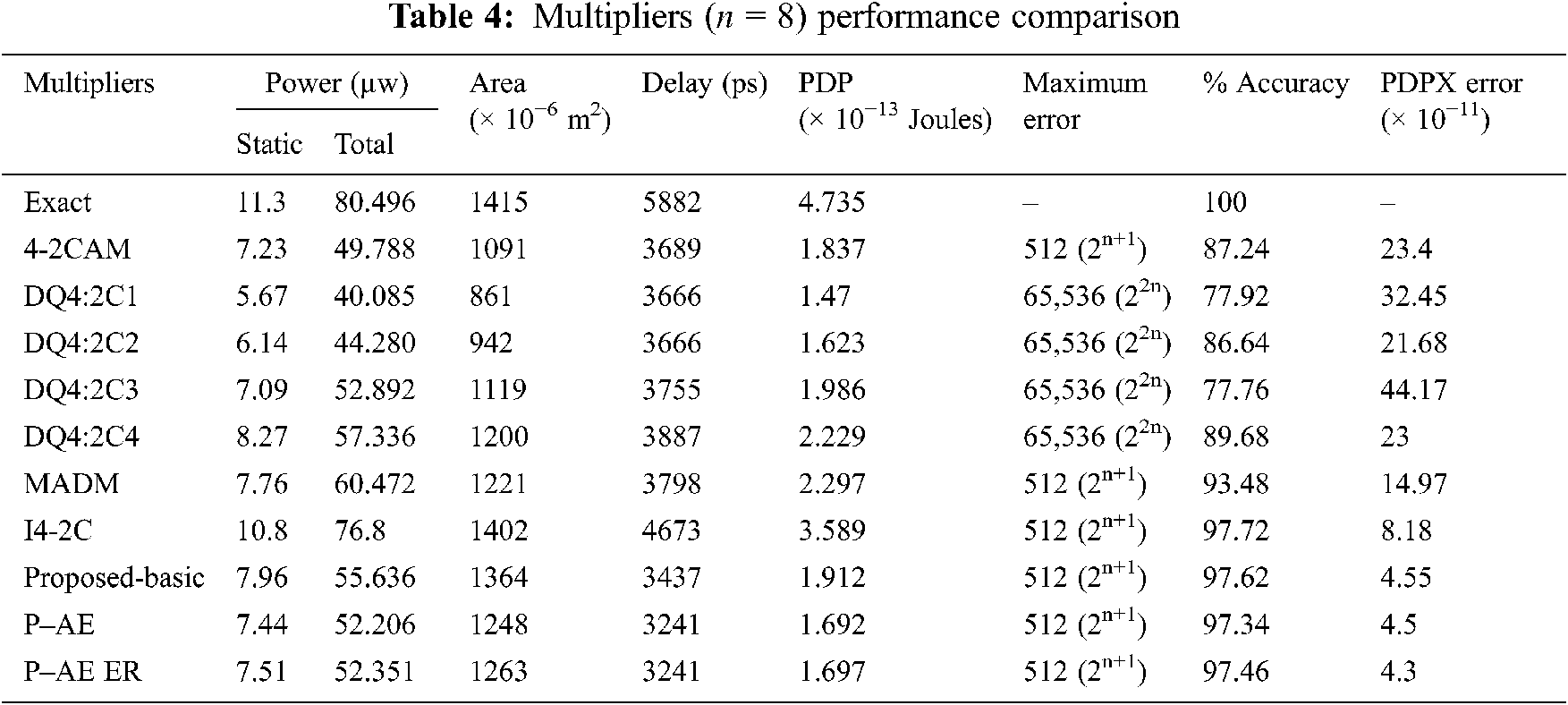
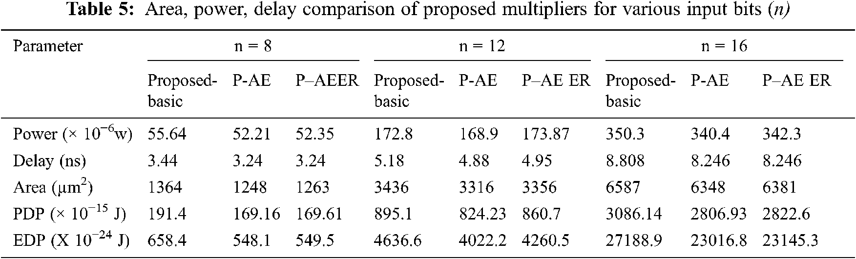

Figure 9: Approximate multipliers (prior) comparison with the proposed multiplier (a) PDP-MRED product (b) Area vs. MRED
5 Implementation in Digital Image Processing
An implementation in image enhancement viz., smoothing & scaling, and signal processing applications is done in FPGA board to justify the novelty of modified multipliers in fault-tolerant image processing applications. The Verilog HDL models of the modified new variant multipliers and futuristic approximate designs defined in the literature are synthesized using Xilinx ISE 14.2 tool, and the prototype model for the application system is made by using Spartan 6 FPGA (XC6XLX45-CSG324 device). Input images and signals are send to the FPGA Board using Xilinx-MATLAB co-simulation with System Generator tool.
In the digital images, Image smoothing technique is performed to reduce the blurring effect and noise. It is a pre-processing operation performed on images prior to the main object extraction. The smoothing operation performs averaging on the pixel intensity values of the input image in a pre-defined window and replaces the processing pixel with the result. The weight of the pixel in the window considered for smoothing operation depends on the type of mask used. For example, filter with 3 × 3 mask replace processing pixel with intensity value G (x, y) defined by
where f(x ± s, y ± t) represents the pixel intensity values of the input image in the window. s, t can take values 0 or 1, and αi represents the corresponding weights in the filter mask. The window is moved pixel by pixel till all the pixels in the input image are processed.

Figure 10: (a) Image of input (b)–(g) Images of output processed with various multipliers for ND = 10% & 20%
Fig. 10 shows the output processed images of the output by the image smoothing system performed along with new variant and other previous tabulated imprecise multipliers. The quality metrics Mean Absolute Error (MAE), Peak Signal to Noise Ratio (PSNR), and Structural Similarity Index (SSIM) [37] are used as measures to evaluate the operation of proposed approximate designs. It is estimated using output images processed by the smoothing system designed with error-tolerant and exact multipliers. MAE PSNR and MSE are defined by Eqs. (18)–(20).
where
G(x, y) and G′(x, y) indicate the image size of the output of the exact and error-tolerant system outputs, a and b. Note that, from Fig. 10, PSNR, MAE, and SSIM output image values are processed by image smoothing system with proposed multipliers–basic, P-AE, P-AE ER designs are more appreciable while comparing approximate multipliers in 4-2 compressor-based approximate multiplier, DQ4:2C1, DQ4:2C2, DQ4:2C3, DQ4:2C4 and Modified architecture of Dadda Multiplier based systems. This is due to the low average error performance of the proposed designs due to faithful approximation. Additionally, we have extracted Average MAE (AMAE) metric using different output images processed by a smoothing system with different standard input images - Lena, Boat, Cameraman, Bridge, Peppers, and shown in Fig. 11. Also by means of Fig. 11, AMAE output image values are processed by proposed-basic, P-AE and P-AE ER designs based systems are significantly better compared to approximate multipliers 4-2 compressor-based approximate multiplier, DQ4:2C1, DQ4:2C2, DQ4:2C3, DQ4:2C4 and Modified architecture of Dadda Multiplierbased systems. AMAE value of approximate multiplier based system fair better compared to the proposed technique and other approximate multiplier systems; however, it exhibits a high area. Also, it is noted that image smoothing system with proposed designs fairs better area compared to systems with designs in Modified architecture of Dadda Multiplier, Imprecise 4-2 compressor and conversely, it is higher when compared to systems with approximate multipliers in 4-2 compressor-based approximate multiplier, DQ4:2C1, DQ4:2C2, DQ4:2C3 and DQ4:2C4.P-AE and P-AEER based smoothing systems fair better processing delay compared to Proposed-basic,Modified architecture of Dadda Multiplier, DQ4:2C3, DQ4:2C4, 4-2 compressor-based approximate multiplier, and Imprecise 4-2 compressor built systems. Imprecise 4-2 compressor based system demonstrates the highest area and processing delay compared to related approximate multiplier smoothing systems.

Figure 11: AMAE Comparison of output images with various multipliers
As implementation of 27 tap Finite impulse Response is done to check the functionality of proposed multiplier. Fig. 12 shows the Data Flow Graph (DFG) of n tap FIR filter. From Fig. 12 it is noted that the multiplier is the significant element that contributes towards the area and critical delay of the FIR filter. Coefficients for the FIR filter are chosen in MATLAB using the Remeez commands. An ECG signal is added and it is fed as an input to the FIR Filter. The processed output signals of the FIR filter implemented with new variant and tabulated previously developed approximate multipliers are measured with standard output to measure the accuracy efficacy of proposed multipliers. The I/O signals processed by the FIR filter designed with various multipliers are illustrated in Figs. 13a–13c. Note from Fig. 13c shows that the output waves.

Figure 12: DFG of FIR filter

Figure 13: (a) Standard ECG input signal (b) ECG signal corrupted by white gaussian noise (c) Output signals processed by FIR filter systems
Processed by Proposed-basic and FIR filters (P-AE based) have small deviations when compared with standard output. Output waves processed by Q4:2C1 and 4-2 compressor-based approximate multiplier FIR systems display the highest and moderate deviations, respectively, compared to the standard output.
In the proposed research work, two area-efficient variants of 4:2 compressors (approximate type) targeted in the multiplier using PP compression. The logic of compressors is realized such that the designs generate sum without error in the first variant and carry without error in the second variant. Evaluations revealed that the proposed compressors fair better with regard to gate count and error reductions while comparing with the previous variants discussed in literature. Implementation of the new variant compressors in the Dadda multiplier disclosed the superior performance of the proposed multiplier with regard to processing speed and accuracy when compared to earlier designs. Enhanced variants of the proposed multiplier in terms of area and error recovery demonstrated better efficacy in terms of area at a trade-off in accuracy. Finally, the proposed multipliers are implemented in signal and image processing applications to verify the functionality and driving quality. Visual examination of processed output images and signals concluded that the proposed inexact multipliers perform similar to the standard design with minimal error deviation.
Acknowledgement: We show gratitude to anonymous referees for their useful ideas.
Funding Statement: The authors received no specific funding for this study.
Conflicts of Interest: The authors declare that they have no conflicts of interest to report regarding the present study.
1. M. J. Schulte and E. E. Swartzlander, “Truncated multiplication with correction constant,” in Proc. of IEEE Workshop on VLSI Signal Processing, Veldhoven, Netherlands, pp. 388–396, 1993. [Google Scholar]
2. J. M. Jou, S. R. Kuang and R. D. Chen, “Design of low-error fixed width multipliers for DSP applications,” IEEE Transactions on Circuits Systems, vol. 46, no. 6, pp. 836–842, 1999. [Google Scholar]
3. K. J. Cho, K. C. Lee, J. G. Chung and K. K. Parthi, “Design of low error fixed-width modified booth multiplier,” IEEE Transactions on Very Large Scale Integration (VLSI) Systems, vol. 12, no. 5, pp. 522–531, 2004. [Google Scholar]
4. T. B. Juang and S. F. Hsiao, “Low-error carry-free fixed-width multipliers with low-cost compensation circuits,” IEEE Transactions Circuits Systems, vol. 52, no. 6, pp. 299–303, 2005. [Google Scholar]
5. J. P. Wang, S. R. Kuang and S. C. Liang, “High-accuracy fixed-width modified booth multipliers for lossy applications,” IEEE Transactions Very Large Scale Integration (VLSI) System, vol. 19, no. 1, pp. 52–60, 2011. [Google Scholar]
6. H. J. Ko and S. F. Hsiao, “Design and application of faithfully rounded and truncated multipliers with combined deletion, reduction, truncation, and rounding,” IEEE Transaction Circuits Systems, vol. 58, no. 5, pp. 304–308, 2011. [Google Scholar]
7. C. Chang and R. K. Satzoda, “A low error and high performance multiplexer-based truncated multiplier,” IEEE Transactions on Very Large Scale Integration (VlSI) Systems, vol. 18, no. 12, pp. 1767–1771, 2010. [Google Scholar]
8. P. R. Cappello and K. Steiglitz, “A VLSI layout for a pipe-lined dadda multiplier,” ACM Transactions on Computer Systems, vol. 1, no. 2, pp. 157–174, 1983. [Google Scholar]
9. V. Gupta, D. Mohapatra, A. Raghunathan and K. Roy, “Low-power digital signal processing using approximate adders,” IEEE Transactions on Computer-Aided Design of Integrated Circuits and Systems, vol. 32, no. 1, pp. 124–137, 2012. [Google Scholar]
10. R. Jothin and C. Vasanthanayaki, “High performance error tolerant adders for image processing applications,” IETE Journal of Research, vol. 67, no. 2, pp. 205–216, 2021. [Google Scholar]
11. A. Dalloo, A. Najafi and A. Garcia-Ortiz, “Systematic design of an approximate adder: The optimized lower part constant-or adder,” IEEE Transactions on Very Large Scale Integration (VLSI) Systems, vol. 26, no. 8, pp. 1595–1599, 2018. [Google Scholar]
12. L. B. Soares, M. M. A. Da Rosa, C. M. Diniz, E. A. C. Da Costa and S. Bampi, “Design methodology to explore hybrid approximate adders for energy-efficient image and video processing accelerators,” IEEE Transactions on Circuits and Systems I: Regular Papers, vol. 66, no. 6, pp. 2137–2150, 2019. [Google Scholar]
13. S. Muthulakshmi, C. S. Dash and S. R. S. Prabaharan, “Memristor augmented approximate adders and subtractors for image processing applications: An approach,” AEU-International Journal of Electronics and Communications, vol. 91, no. 7, pp. 91–102, 2018. [Google Scholar]
14. A. B. Kahng and S. Kang, “Accuracy-configurable adder for approximate arithmetic designs,” in Proc. of the 49th Annual Design Automation Conf., San Francisco, California, USA, pp. 820–825, 2012. [Google Scholar]
15. Y. Guo, L. Guo, S. Kimura and H. Sun, “Low-cost approximate multiplier design using probability-driven inexact compressors,” in IEEE Asia Pacific Conf. on Circuits and Systems (APCCAS), Chengdu, China, pp. 291–294, 2018. [Google Scholar]
16. K. M. Reddy, M. Vasantha, Y. B. Nithin Kumar and H. Devesh Dwivedi, “Design and analysis of multiplier using approximate 4-2 compressor,” International Journal of Electronics and Communication, vol. 107, no. 7, pp. 89–97, 2019. [Google Scholar]
17. I. Alouani, H. Ahangari, O. Ozturk and S. Niar, “A novel heterogeneous approximate multiplier for low power and high performance,” IEEE Embedded System Letter, vol. 10, no. 2, pp. 45–48, 2018. [Google Scholar]
18. M. Ha and S. Lee, “Multipliers with approximate 4-2 compressors and error recovery modules,” IEEE Embedded Systems Letter, vol. 10, no. 1, pp. 6–9, 2018. [Google Scholar]
19. D. Baran, M. Aktan and V. G. Oklobdzija, “Energy efficient implementation of parallel CMOS multipliers with improved compressors,” in ACM/IEEE Int. Symp. on Low-Power Electronics and Design (ISLPED), Austin, TX, USA, pp. 147–152, 2010. [Google Scholar]
20. C. Liu, J. Han and F. Lombardi, “A low-power, high-performance approximate multiplier with configurable partial error recovery,” in Design, Automation & Test in Europe Conf. & Exhibition (DATE), Dresden, Germany, pp. 1–4, 2014. [Google Scholar]
21. A. Momeni, J. Han, P. Montuschi and F. Lombardi, “Design and analysis of approximate compressors for multiplication,” IEEE Transactions on Computers, vol. 64, no. 4, pp. 984–994, 2015. [Google Scholar]
22. P. Sonwane, P. Malathi and M. Sharma, “Design of low power inexact 4:2 compressor using approximate adder,” in Int. Conf. on Computer, Communication and Control (IC4), Indore, India, pp. 1–5, 2015. [Google Scholar]
23. K. Y. Kyaw, W. L. Goh and K. S. Yeo, “Low-power high-speed multiplier for error-tolerant application,” in IEEE Int. Conf. on Electron Devices Solid-State Circuits (EDSSC), Hong Kong, China, pp. 1–4, 2010. [Google Scholar]
24. G. Wang and J. Shield, “The efficient implementation of an array multiplier,” in IEEE Int. Conf. on Electro Information Technology, Lincoln, NE, USA, pp. 5–15, 2005. [Google Scholar]
25. Y. J. Chang, Y. C. Cheng, Y. F. Lin, S. C. Liao, C. H. Lai et al., “Imprecise 4-2 compressor design used in image processing applications, IET Circuits,” Devices & Systems, vol. 13, no. 6, pp. 848–856, 2019. [Google Scholar]
26. O. Akbari, M. Kamal, A. Afzali-Kusha and M. Pedram, “Dual-quality 4:2 compressors for utilizing in dynamic accuracy configurable multipliers,” IEEE Transactions on Very Large Scale Integration (VLSI) Systems, vol. 25, no. 4, pp. 1352–1361, 2017. [Google Scholar]
27. C. H. Chang, J. Gu and M. Zhang, “Ultra low-voltage, low power CMOS 4-2 and 5-2 compressors for fast arithmetic circuits,” IEEE Transactions on Circuits and Systems, vol. 51, no. 4, pp. 1985–1997, 2004. [Google Scholar]
28. S. F. Hsiao, M. R. Jiang and J. S. Yeh, “Design of high-speed low-power 3-2 counter and 4-2 compressor for fast multipliers,” Electron Letters, vol. 34, no. 4, pp. 341–343, 1998. [Google Scholar]
29. N. Sureka, R. Porselvi and K. Kumuthapriya, “An efficient high speed wallace tree multiplier,” in Int. Conf. on Information Communication and Embedded Systems (ICICES), Chennai, India, pp. 1023–1026, 2013. [Google Scholar]
30. S. Venkatachalam, H. J. Lee and S. B. Ko, “Power efficient approximate booth multiplier,” in IEEE Int. Symp. on Circuits and Systems (ISCAS), Florence, Italy, pp. 1–4, 2018. [Google Scholar]
31. Z. Wang, G. A. Jullien and W. C. Miller, “A new design technique for column compression multipliers,” IEEE Transactions on Computers, vol. 44, no. 8, pp. 962–970, 1995. [Google Scholar]
32. S. Venkatachalam and S. B. Ko, “Design of power and area efficient approximate multipliers,” IEEE Transactions on Very Large Scale Integration (VLSI) Systems, vol. 25, no. 5, pp. 1782–1786, 2017. [Google Scholar]
33. C. H. Lin and I. C. Lin, “High accuracy approximate multiplier with error correction,” in IEEE 31st Int. Conf. on Computer Design (ICCD), Asheville, NC, USA, pp. 33–38, 2013. [Google Scholar]
34. S. Narayanamoorthy, H. A. Moghaddam, Z. Liu, N. S. Kim and T. Park, “Energy- efficient approximate multiplication for digital signal processing and classification applications,” IEEE Transactions on Very Large Scale Integration (VLSI) System, vol. 23, no. 6, pp. 1180–1184, 2015. [Google Scholar]
35. A. Saha, R. Pal, A. G. Naik and D. Pal, “Novel CMOS multi-bit counter for speed-power optimization in multiplier design,” AEU-International Journal of Electronics and Communications, vol. 95, no. 8, pp. 189–198, 2018. [Google Scholar]
36. G. Zervakis, S. Xydis, K. Tsoumanis, D. Soudris and K. Pekmestzi, “Hybrid approximate multiplier architectures for improved power-accuracy trade-offs,” in IEEE/ACM Int. Symp. on Low Power Electronics and Design (ISLPED), Rome, Italy, pp. 79–84, 2015. [Google Scholar]
37. G. Palanisamy, V. K. Natarajan and K. Sundaram, “Area-efficient parallel adder with faithful approximation for image and signal processing applications,” IET Image Processing, vol. 13, no. 13, pp. 2587–2594, 2019. [Google Scholar]
 | This work is licensed under a Creative Commons Attribution 4.0 International License, which permits unrestricted use, distribution, and reproduction in any medium, provided the original work is properly cited. |