DOI:10.32604/csse.2022.022368
| Computer Systems Science & Engineering DOI:10.32604/csse.2022.022368 | |
| Article |
SOINN-Based Abnormal Trajectory Detection for Efficient Video Condensation
1National Taiwan University of Science and Technology, Taipei City, 106335, Taiwan
2Soochow University, Taipei City, 100, Taiwan
3Tamkang University, New Taipei City, 251301, Taiwan
4Chung Yuan Christian University, Taoyuan City, 32023, Taiwan
*Corresponding Author: Chang-Yi Kao. Email: edenkao@scu.edu.tw
Received: 05 August 2021; Accepted: 10 September 2021
Abstract: With the evolution of video surveillance systems, the requirement of video storage grows rapidly; in addition, safe guards and forensic officers spend a great deal of time observing surveillance videos to find abnormal events. As most of the scene in the surveillance video are redundant and contains no information needs attention, we propose a video condensation method to summarize the abnormal events in the video by rearranging the moving trajectory and sort them by the degree of anomaly. Our goal is to improve the condensation rate to reduce more storage size, and increase the accuracy in abnormal detection. As the trajectory feature is the key to both goals, in this paper, a new method for feature extraction of moving object trajectory is proposed, and we use the SOINN (Self-Organizing Incremental Neural Network) method to accomplish a high accuracy abnormal detection. In the results, our method is able to shirk the video size to 10% storage size of the original video, and achieves 95% accuracy of abnormal event detection, which shows our method is useful and applicable to the surveillance industry.
Keywords: Surveillance systems; video condensation; SOINN; moving trajectory; abnormal detection
The surveillance systems are set around our life for public and private safety. To record all possible anomalies within the view of the cameras, the surveillance videos are produced continuously every day around the clock. With the advancement of imaging systems, both the resolution and file size have increased. However, the compression rate of the state-of-the-art algorithms do not reduce as much file size as they increased. In addition, the surveillance videos are preserved more than one month by users, which indicates that there is a huge amount of video to be stored. Therefore, the storage capacity is crucial to the surveillance systems, and engineers seek for efficient strategies for file size reduction in surveillance videos.
On the other hand, humans have limited concentration in watching surveillance videos, particularly when most of the scenes are redundant and similar. The attention of the forensic officers would decrease as the video plays, and thus missing some key events in the video. To prevent this situation, computer-aided intelligent surveillance is helpful in this regard.
To solve the issues above, we propose a method which includes two major functionalities required for the surveillance industry, which are efficient data storage and intelligent surveillance. We extract the moving objects from the videos along with their trajectories and original images, and rearrange them to build a new video with reduced file size and enhanced observability. The rearrangement is by means of a technique of video condensation and abnormal detection.
Video condensation, also called video synopsis [1], is a method to rearrange the sequence of moving objects within a video, which is useful when there are many vacant spaces in most of the video parts. The condensation method is performed by pulling moving objects in the video from different time and make them show up simultaneously to fill up the vacant spaces among video frames. Different from video compression, video condensation works on content analysis rather than traditional information theory, and is possible to reduce times of file size than traditional video compression methods.
1.2 Intelligent Video Surveillance
Traditionally, the surveillance video observers, often forensic officers, watch the video to find some clues for crime solving manually, which is labor-consuming and inefficient for crime solving. Therefore, intelligent video surveillance systems [2] are developed to find anomalies automatically. Usually, abnormal events are obviously different from normal ones, and intelligent systems works on the induction of unique features of abnormal events using statistics and some machine learning strategies.
According to [3], the methods for detection can basically partition into four categories: 1) knowledge-based, 2) feature invariant, 3) template matching, and 4) appearance-based. Appearance-based methods highlight relevant characteristics of the face images by machine learning from a training set. The eigenface-based methods [4,5] are particular techniques grouped into this category. An et al. also completed a tracking system using a simple linear Kalman filter [6]. In addition to the Kalman filter, K. Y. Wang proposed a real-time face tracking system based on particle filtering techniques. Shan et al. [7] proposed a new tracking algorithm named MSEPF (Mean Shift Embedded in a Particle Filter). Elmenzain et al. [8] have proposed a system to recognize the alphabets and numbers in real time based on hidden Markov models.
Our proposed system is a combination of video condensation and intelligent video surveillance, which aims at shirking video size by segmenting foreground and background, and rearrange its containing objects by sorting the degree of anomaly of each object. The system moves the detected abnormal moving objects to the front of the surveillance video, and other normal objects to the latter parts. The flow chart of the proposed method is shown in Fig. 1.

Figure 1: Flow chart of the proposed system
Particularly, our abnormal detection method is implemented by SOINN [9] clustering algorithm. The SOINN is a semi-supervised incremental machine learning method, which supports on-line learning. SOINN also allows partially labelled inputs, which meets the demands of existing intelligent surveillance systems.
2 Trajectory Feature Extraction
In this paper, both the condensation and abnormal detection relies on the correct information of the trajectory of moving objects. The moving objects can be obtained by the subtraction of GMM (Gaussian Mixture Model) [10] produced background, but there are some drawbacks and issues on GMM. In this section, we propose the improved foreground segmentation and occlusion handling method to attain a more accurate trajectory feature extraction by GMM.
2.1 Proposed Foreground Segmentation Method
In most of the work, the foreground mask is obtained by the subtraction of GMM generated background. However, because some pixels are similar to the background, the produced foreground will contain holes, as shown in Fig. 2.

Figure 2: Foreground mask extracted from GMM background
To solve the problem, we improve the foreground mask of each object by the following steps: first, use a bounding box to frame the objects and perform magnification; second, apply the Gaussian-based contour detection to the magnified bounding box; finally, perform morphological operations, such as opening and closing the fill the holes inside the contours. The process is illustrated in Fig. 3.

Figure 3: Improve foreground extraction by magnification
Condensation is a kind of synthesis, so the extracted foregrounds should have smooth edges otherwise there will be gaps in the synthesized frames. To smooth the edges, the following steps are performed: first, we convert the foreground images to grayscale by the following formula with weighted RGB channels:
where F is the foreground image.
The Gaussian blur filter is applied as a low-pass filter to reduce images noises in the grayscale foreground. The Gaussian mask is obtained by the following formula:
where σ is the standard deviation of the Gaussian function.
After applying the Gaussian blur to the foreground image and the smoothed foreground.
Subsequently, we detect contours within the bounding boxes by setting an adaptive threshold to remove the noises. The adaptive threshold T (x, y) is set adaptively on a pixel-by-pixel basis by computing a weighted average of the r-by-r region around each pixel location minus a constant which is empirically set to 5, where r is a mask size the same value as the Gaussian blur filter.
We apply the adaptive threshold to the following formula to detect the contour edge of a moving object.
where B is the obtained binary contour image of a moving object, and S is the blurred grayscale foreground.
The detection method is useful especially when there are strong illumination or reflectance gradients.
After removing the noises within the foreground, we remove the regions belong to the background, as illustrated in Fig. 4, which is performed by subtracting the edges of the background image.

Figure 4: Example of contour detection
Finally, the moving object mask is reconstructed by adding original foreground mask to the contour produced by the above steps, and the result is shown in Fig. 5. The result can be improved again by using morphological operations to fill the holes and remove noises.

Figure 5: Example of reconstructing foreground of moving objects
After producing the foreground mask of objects in each frame, the foreground images can be extracted. In a moving object, the image sequence and their respective coordinates in the video can be extracted and saved as a new data structure as Fig. 6 shows. which redundant background pixels are discarded, and the video condensation is accomplished.

Figure 6: An example of a folder with data of a processed surveillance video, each folder includes a moving object trajectory with its foreground image
2.2 Image Processing for De-Condensation
After the foreground mask is obtained, its image sequence can be shifted to arbitrary parts of the surveillance video. The de-condensation process is performed by synthesizing the image sequence of a moving object to the surveillance video’s background image, which can be formulated as follows:
where Io is the foreground image of a moving object, Ib is the background image of the surveillance video, Mo is the foreground mask obtained from last section, and It is the synthesized image frame of the de-condensed video. The process is depicted in Fig. 7.

Figure 7: Replacement of original moving object image
If the foreground images are extracted in a rectangular shape, there will be sharp edges at the boundary after synthesis. To solve this issue, modify the foreground mask by padding some foreground pixels at the boundary in the mask Mo, and form a new mask Mr. The processed mask is shown in Fig. 8.

Figure 8: Replacement of original moving object image

Figure 9: Example of eliminating sharp edges: (a) without using mobbing objects’ image pre-processing; (b) using moving objects’ image pre-processing
Subsequently, use Mr to construct Gaussian pyramid, and then use Laplacian pyramid image fusion to fuse It and Ib. The image Ir is the result of fusing and it has been smoothed the sharp edges in It. An example of eliminating sharp edges as motorcycle image preprocessing is shown in Fig. 9.
If two or more moving objects are too close to each other while moving, the foreground mask of a moving object may include some parts of others’ as shown in Fig. 10.

Figure 10: Example of magnifying bounding box including the part of another moving object: (a) before magnifying; (b) after magnifying
The appearance model [11] is constructed to distinguish different Blobs in occlusion. The appearance model is based on the RGB color model which shows the appearance of each pixel of the moving object with a correlative probability mask MRGB(x) recording the probability of the moving object Pc(x) observed at the corresponding pixel.
When a new Blob is created, a rectangular appearance model is constructed with the same size as the bounding box of the Blob. MRGB(x) is initialized with the pixel values of the moving object into the color model, and Pc(x) is initialized to 0.4. If the value of the pixel corresponding to the Blob’s foreground mask is zero, the probability of pixel in Pc(x, y) is initialized to zero. Then the appearance of model is updated by the following formulas.
where f is the set of pixels of foreground, and α is set to 0.95.
The appearance model is updated continuously until its correspondence Blob disappears from the field of view.
The appearance model has each Blob pixel’s accumulated information. p(I, x, M) represents accumulated RGB probability maximized over a small search region. The maximum value position is set as the Blob’s location. p(I, x, M) is defined as follows.
To prevent occlusion from overlapping, find the “dispute pixels” in the appearance model. The probability of pixel i is formulated as:
If
After applying the appearance model, the Blobs of each occluded pixels can be distinguished to their respective objects. In Fig. 11, the blue word in frame is the ID of Blob. We successfully separate the two Blobs from overlapping Blobs.

Figure 11: Example of moving object occlusion resolution: (a) before occlusion; (b) occlusion
After the information of trajectories in a surveillance video is extracted, they are used for our proposed abnormal detector. In the detector, first, the trajectories of normal and abnormal moving objects are collected and labelled; second, we use the SOINN machine learning model to build the detector. The model is employed to analyze moving objects in real time to find out abnormal moving objects in sequences of image frames.
In practice, the coordinate of the objects is discrete, and is in a non-continuous zig-zag form. We exploit the Kalman filter [12] based on linear regression to process the original trajectory points to obtain a set of smoothened trajectory points. Each trajectory point consists of a feature vector as expressed as follows.
And:
where xt and yt are the location of a moving object at frame t; both the location differences dxt and dyt are calculated by dxt = xt − xt−1 and dyt = yt − yt−1 in the tth frame, respectively.
After tracking n successive frames, a trajectory of length n is extracted. Thus, all the trajectory Ti is linked to form a trajectory T of length m, where Ti is the trajectory of the ith moving object and m = n × i. T is composed of the trajectories of all the objects in the scene.
The next step is the normalization of the feature values of a moving object, where the positions of x and y are normalized to the range of 0∼1 using:
where width and height represent the width and height of a frame, respectively. For the moving orientation θ, we normalize the 0∼359 to 0∼1 accordingly.
3.2 Abnormal Detection Using SOINN
We collect trajectory information of moving objects in the scene
The SOINN [9] model is employed to analyze moving objects in the real-time camera frames and find out abnormal moving objects.
The trajectory of the ith moving object is denoted as Ti = {(x1, y1, dx1, dy1), ⋅ ⋅ ⋅ , (xn, yn, dxn, dyn)}. There are several groups in the model, and the abnormal moving object detection system examines whether Ti belongs to a normal group. If the trajectory Ti does not belong to any normal groups, the trajectory is detected to be abnormal. The detail of the anomaly detection steps is listed as follows:
1. Build a neural network with an empty node Q
2. Input new pattern F into Q as a vector VF, where F ∈ Ti and Ti is the trajectory of length n of the ith object composed of F = (xp, yp, xv, yv).
3. Calculate the Euclidean distance between VF and Vq, and determine the top two winners s1 and s2 as follows:
4. Calculate
5. Calculate the Euclidean distance DF between F and node s by:
6. Calculate the sum of DF and τs of all Fi=1,⋅⋅⋅,n respectively by:
7. Calculate the degree of abnormal object trajectory by:
8. In the real world, the definition of abnormality is a fuzzy concept. In addition, the occurrence of abnormal moving objects is continuous. Hence, we set threshold
Finally, according to the clustering result from SOINN, we use OA to indicate whether a moving object is abnormal. When a moving object is detected as abnormal, the system is able to alarm the users that some anomalies occur.
The SOINN autonomously detects abnormal trajectories based on the built model. However, without prior knowledge, some obvious abnormal objects need long learning time to be detected. Therefore, the feedback mechanism is designed by implementing a user interface which accepts human markups. Suppose that we have already known some forbidden areas, we can mark these areas up with a rectangular markup in Fig. 12, which any objects trespassed the regions are labelled as abnormal, and these object trajectories are retrained and update the SOINN model. In [13], Ashish mentions that the multicue feature fusion ensures that the limitations of the individual cue are suppressed and complementary in the unified feature. Sensors fusion in intelligent surveillance system is our directions for learning method improvement.

Figure 12: The feedback learning surveillance interface: (a) set a green bounding box as a normal area; (b) set a red bounding box as an abnormal area
In this section, the experimental results of two major contributions of this paper are presented as the video condensation rate and abnormal detection accuracy.
In the experiment, three types of video have been used to verify the performance of our proposed method. The scenes are square, campus, and freeway, respectively. On the orientation of the moving objects, the square scene has the highest degree of freedom, the freeway scene has the lowest, and the campus scene is in the midst of the other two. Tab. 1 shows the size and other related information of the three scene type video.

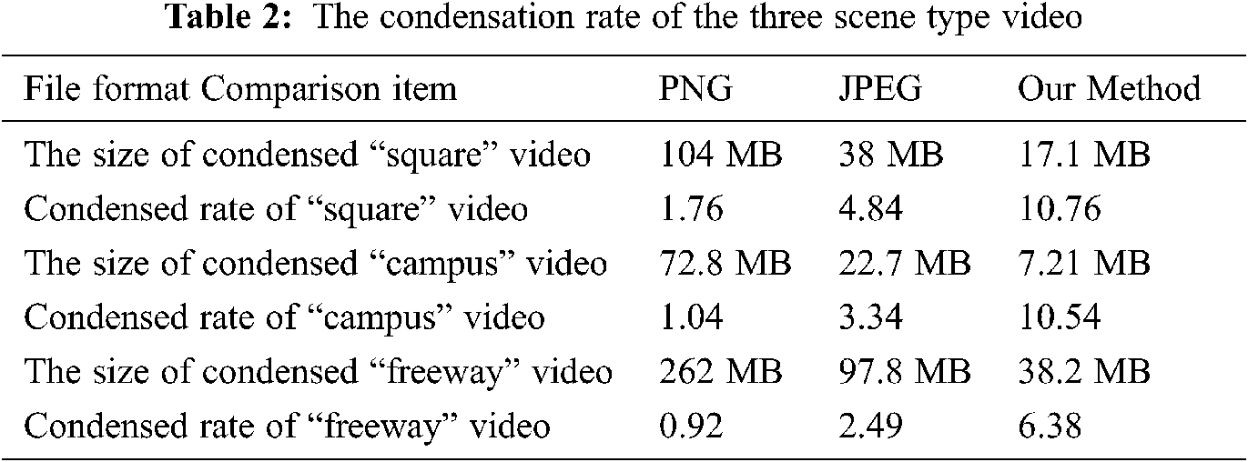
4.2 Results on Condensation Rate
To evaluate the performance of surveillance video size reduction, the condensation rate, which is defined as the time that the video size has reduced.
Tab. 2 shows the condensation rate of the three scenes of the video, which shows that our method is more efficient in video size reduction than other most used image compression formats. In addition, the scenes with higher degree of freedom in orientation has better condensation rate.
4.3 Results on Abnormal Detection Accuracy
The abnormal detection accuracy is evaluated on each trajectory, and perform statistics on the correctly classified count. We use the accuracy equation as follows as a statistical measure.
where TP is for the number of true positive samples, TN is for the number of true negative samples, FP is for the number of false positive samples, FN is for the number of false negative samples. Accuracy is the most common model measurement tool. Precision places more emphasis on the “model predicted to be true” result. The recall rate puts more emphasis on the “true-to-life” results. In the proposed method, it should be judged that both “prediction” and “judgment” are completely correct samples.
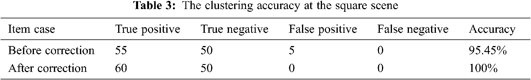
To evaluate the effectiveness after applying the improvements of trajectory feature enhancement, we use the square and campus scene to compare the accuracy before and after application. Tabs. 3 and 4 shows the improvement of accuracy after applying the enhancement methods.

In addition, we also compare the accuracy by detecting the abnormal moving object by single feature only, and Tabs. 5 and 6 shows that both scenes have high accuracy using our detection method, but the content of the video decides which feature has the best accuracy.


In this paper, we have proposed a new video condensation method which rearranges the moving sequence of the video to reduce video size and improves observability for forensic officers. The video can be reduced to 10 times as the original video, and the accuracy of the abnormal detection is around 95%.
However, without prior knowledge sent to the SOINN, the feedback mechanism is still required during the learning process in the proposed method. In the future, it should consider that the avoids the eventual drift of the tracker during illumination variation, rotation, and deformation. To ensure more robustness and accuracy in rainy days or crowded environments. In the future, we would develop a knowledge based mechanism for abnormal detection to efficiently reduce learning time of the abnormal detection method.
Acknowledgement: The authors thank to National Taiwan University of Science and Technology that providing the campus venue for the video shooting.
Funding Statement: The authors received no specific funding for this study.
Conflicts of Interest: The authors declare that they have no conflicts of interest to report regarding the present study.
1. A. Rav-Acha, Y. Pritch and S. Peleg, “Making a Long Video Short: Dynamic Video Synopsis,” in Proc. of Int. Conf. of Computer Vision and Pattern Recognition, New York, NY, pp. 435–441, 2006. [Google Scholar]
2. W. Li, V. Mahadevan and N. Vasconcelos, “Anomaly detection and localization in crowded scenes,” IEEE Transactions on Pattern Analysis and Machine Intelligence, vol. 36, no. 1, pp. 18–32, 2014. [Google Scholar]
3. M. H. Yang, D. Kriegman and N. Ahuja, “Detecting faces in images: A survey,” IEEE Transactions on Pattern Analysis and Machine Intelligence, vol. 24, no. 1, pp. 34–58, 2002. [Google Scholar]
4. R. Vaillant, C. Monrocq and Y. L. Cun, “An Original Approach for the Localization of Objects in Images,” in Proc. of the IEEE Conf. on Artificial Neural Networks, Brighton, UK, pp. 26–30, 1993. [Google Scholar]
5. M. Turk and A. Pentland, “Eigenfaces for recognition,” Journal of Cognitive Neuroscence, vol. 3, no. 1, pp. 71–86, 1991. [Google Scholar]
6. K. H. An, D. H. Yoo, S. U. Jung and M. J. Chung, “Robust Multi-View Face Tracking,” in Proc. of the IEEE Int. Conf. on Intelligent Robots and Systems,” Edmonton, Canada, pp. 1905–1910, 2005. [Google Scholar]
7. C. Shan, Y. Wei, T. Tan and F. Ojardias, “Real Time Hand Tracking by Combining Particle Filtering and Mean Shift,” in Proc. of the Sixth IEEE Int. Conf. on Automatic Face and Gesture Recognition, Seoul, South Korea, pp. 669–674, 2004. [Google Scholar]
8. M. Elmezain, A. Al-Hamadi and B. Michaelis, “Real-time capable system for hand gesture recognition using hidden markov models in stereo color image sequences,” Journal of WSCG, vol. 16, no. 1–3, pp. 65–72, 2008. [Google Scholar]
9. F. Shen and O. Hasegawa, “Self-organizing Incremental Neural Network and its Application,” in Proc. of Int. Conf. on Artificial Neural Networks, Thessaloniki, Greece, pp. 535–540, 2010. [Google Scholar]
10. Z. Zivkovic, “Improved Adaptive Gaussian Mixture Model for Background Subtraction,” in Proc. of Int. Conf. on Pattern Recognition, Cambridge, UK, pp. 28–31, 2004. [Google Scholar]
11. A. Senior, A. Hampapur, Y. L. Tian, L. Brown, S. Pankanti et al., “Appearance models for occlusion handling,” Image and Vision Computing, vol. 24, no. 11, pp. 1233–1243, 2006. [Google Scholar]
12. D. Sierociuk and A. Dzieliński, “Fractional kalman filter algorithm for the states, parameters and order of fractional system estimation,” International Journal of Applied Mathematics and Computer Science, vol. 16, no. 1, pp. 129–140, 2006. [Google Scholar]
13. K. Ashish, S. W. Gurjit, and S. Kapil, “Robust object tracking based on adaptive multicue feature fusion,” Journal of Electronic Imaging, vol. 29, no. 6, pp. 063001, 2020. [Google Scholar]
 | This work is licensed under a Creative Commons Attribution 4.0 International License, which permits unrestricted use, distribution, and reproduction in any medium, provided the original work is properly cited. |