DOI:10.32604/csse.2022.023102
| Computer Systems Science & Engineering DOI:10.32604/csse.2022.023102 | |
| Article |
A Compact Self-Isolated MIMO Antenna System for 5G Mobile Terminals
1Microwave Research Group, Department of Electrical Engineering, University of Technology, Baghdad, 10001, Iraq
2Microwave Research Group, Department of Communication Engineering, University of Technology, Baghdad, 10001, Iraq
*Corresponding Author: Muhannad Y. Muhsin. Email: muhannad.y.muhsin@uotechnology.edu.iq
Received: 27 August 2021; Accepted: 28 September 2021
Abstract: A compact self-isolated Multi Input Multi Output (MIMO) antenna array is presented for 5G mobile phone devices. The proposed antenna system is operating at the 3.5 GHz band (3400–3600 MHz) and consists of eight antenna elements placed along two side edges of a mobile device, which meets the current trend requirements of full-screen smartphone devices. Each antenna element is divided into two parts, a front part and back part. The front part consists of an I-shaped feeding line and a modified Hilbert fractal monopole antenna, whereas the back part is an L-shaped element shorted to the system ground by a 0.5 mm short stub. A desirable compactness can be obtained by utilizing the Hilbert space-filling property where the antenna element’s overall planar size printed on the side-edge frame is just (9.57 mm × 5.99 mm). The proposed MIMO antenna system has been simulated, analyzed, fabricated and tested. Based on the self-isolated property, good isolation (better than 15 dB) is attained without employing additional decoupling elements and/or isolation techniques, which increases system complexity and reduces the antenna efficiency. The scattering parameters, antenna efficiencies, antenna gains, and antenna radiation characteristics are investigated to assess the proposed antenna performance. For evaluating the proposed antenna array system performance, the Envelope Correlation Coefficients (ECCs), Mean Effective Gains (MEGs) and channel capacity are calculated. Desirable antenna and MIMO performances are evaluated to confirm the suitability of the proposed MIMO antenna system for 5G mobile terminals.
Keywords: 5G applications; compact antennas; isolation techniques; MIMO antennas; mobile terminals; self-isolated antennas
With increasing growth of wireless communication technologies, high data rates and intelligent services are being continuously demanded. Because of the advantages of large channel capacity, massive connection density and high spectral efficiency, the 5G wireless communication systems have attracted increasing attention in both academic and industrial fields [1]. One of the essential enabling technologies for the 5G communication systems is the Multiple Input Multiple Output (MIMO) technology. By utilizing the multipath property of the wireless communication environment, a MIMO system can improve the spectral efficiency and channel capacity without needing more bandwidth and/or transmitting power [2]. Whenever increasing MIMO system’s antenna elements, larger channel capacity and more link reliability can be obtained. However, because of mobile devices’ limited space, the mutual coupling problem is becoming more pronounced with more penetration of antennas. The MIMO system’s performance is severely affected by the mutual coupling impact [3]. So, various techniques have been employed and provided reasonable solutions to solve this problem. One of these techniques includes the spatial diversity method [4–6]. Good isolation can be obtained by this method but at the expense of decreasing the number of antennas, where the space variation between antennas is used as a key approach to achieve low mutual coupling. Isolation enhancement can be done with more compactness than the spatial diversity method by employing the polarization diversity method [7,8], and the pattern diversity method [9,10]. However the compact size and simple structure design of 5G mobile devices, which have high diversity performance capability with low ECCs, remains a highly requested aim for antenna engineers in designing MIMO antenna systems. Moreover, many other isolation techniques using external decoupling structures have been reported in the literature including parasitic structure [11,12], hybrid elements (neutralization line and parasitic element) [13], neutralization line [14,15], decoupling network [16,17], slot etching [18], hybrid decoupling like ground slot etching and meandered line parasitic element [19] or ground slot and neutralization line [20], and multimode decoupling technique [21]. Although these isolation techniques, which are based on additional decoupling structures, provide good isolation enhancement, the antenna efficiency might be reduced significantly. In other words, the isolation improvement is done at the expense of the antenna efficiency. For example, the antenna efficiency in [15] and [21] is affected notably, decreasing to 30% and 34%, respectively. Good isolation and antenna performance have been reported by utilizing the self-isolated technique [22]; however, the antenna element size is too large. In a self-isolated property, an antenna element operates as a radiated element as well as an isolation one at the same time. So, there will be no need for additional decoupling elements or/and isolation techniques. Nevertheless, a compact-size massive MIMO antenna system with good isolation and high efficiency for 5G mobile devices is still a challenge.
In this paper, a compact self-isolated eight-element antenna system that operates in the (3400–3600 MHz) band is presented for future 5G MIMO mobile handsets. The main feature of this work is that it can effectively solve the isolation problem with keeping high antenna efficiency. Based on the self-isolated property, good isolation is obtained without utilizing decoupling elements and/or isolation techniques. In addition to that, a compact antenna size and simple structure is presented in the proposed system where the antenna element’s overall planar size printed on the side-edge frame is just (9.57 mm × 5.99 mm). Furthermore, a high diversity performance with very low envelope correlation coefficients (ECCs) is attained, where a very good independence antenna’s far-field radiation characteristics can be shown. Besides, good antenna and MIMO performances are achieved. The proposed antenna system was simulated and analyzed using the CST Microwave Studio software (version 2019). A prototype model of the proposed system was fabricated and its performance was measured. Reasonable agreement between the measured and simulated results has been obtained.
The proposed eight-element MIMO antenna system for 5G mobile phones is presented in Fig. 1. The eight antenna elements of the proposed MIMO system are located over a mobile device’s two long side edges. The main board size is (150 × 75) mm2. This is a typical size of a 5.5-inch phone device. A side edge frame of 7 mm height is selected for a slim smartphone device requirement. Both the system circuit board and the frame are designed by employing a double-sided FR4 substrate of 0.8 mm height. It has an approximate relative permittivity of 4.3 and a dielectric loss tangent of 0.02. At the bottom and the top of the main system board, two clearance areas are left for the current 4G antennas and other different antennas. The size of each clearance area is (8 × 75) mm2. As can be observed from Fig. 1, the eight antenna elements are printed on the inner and outer surfaces of the two long side-edges of the frame substrate. They are located perpendicularly on the mobile device’s main substrate, with each side having four antenna elements. All antennas have the same structure and dimensions. A 50 Ω SMA connector is employed for feeding antenna elements via holes from the backside of the main system ground. As illustrated in Fig. 1, the distance between the front sides of the antennas which are printed on the inner frame surfaces is descried by D, and the distance between the back sides of the antenna elements is denoted by d, while the distance between the antenna feeding lines is indicated by DL. For example, D15 means the distance between the front sides of Ant1 and Ant5 and so on. In addition to that, the four antennas located at the mobile frame’s corners are symbolized as Ant1, Ant2, Ant3 and Ant4, while the four antennas located at the middle of the mobile frame are denoted by Ant5, Ant6, Ant7 and Ant8. The following parameters are optimized for the proposed MIMO antenna system (D15 = D47 = D26 = D38 = 30.43 mm, D56 = D78 = 34.13 mm), (d15 = d47 = d26 = d38 = 33 mm, d56 = d78 = 39.27 mm), and (DL15 = DL47 = DL26 = DL38 = 39.62 mm, DL56 = DL78 = 34.13 mm). One can observe from the distance parameters the similarity of the frame long side-edges.

Figure 1: The proposed eight-element MIMO antenna system
Fig. 2 shows the perspective view of a single self-isolated compact antenna element. As seen from this figure, the antenna element can be divided into two parts, a front part and a back part. Fig. 3 depicts the detailed structure of the two parts. The front part of the antenna, as observed in Fig. 3a, consists of an I-shaped feeding line and a modified Hilbert fractal monopole antenna. The second iteration of the Hilbert fractal geometry is considered and its modification is done by extending its long arm length. The symbol FL is used to describe the I-shaped feeding line which is fine-tuned for matching purposes. The long line length of the Hilbert’s arm is represented by LL and the short one is described by LS. Very good antenna miniaturization is obtained by utilizing the Hilbert space-filling property, where the antenna element overall planar size is just (9.57 mm × 5.99 mm) which operates at the desired (3.4–3.6) GHz band. Due to its small-size characteristic of 0.111

Figure 2: Three-dimensional view of the single antenna element

Figure 3: Single element front part (a) and back part (b)
To further demonstrate the working principle of the proposed compact self-isolated antenna element, the effects of LL and VL on the input reflection coefficient have been demonstrated as depicted in Figs. 4 and 5, respectively. Fig. 6 illustrates the surface current distribution at 3.5 GHz. One can see from Fig. 4 that four values have been chosen for LL: 7.5 mm, 7.7 mm (the proposed one), 8 mm and 8.5 mm. As expected, the antenna resonance frequency shifts according to the antenna length. So in this case study, the antenna resonance frequency shifts to a lower value as the effective value of LL increases. As can be observed form Fig. 5 that four values have been introduced for the VL parameter which are 2.85 mm, 3.85 mm, 5.85 mm (the proposed one) and 6.85 mm. So the optimized VL parameter value, which is an effective parameter of the coupling capacitance generated by the virtual antenna ground, plays a vital role for obtaining a very good impedance matching. In addition to that, the virtual antenna ground (L-shaped shorted-stub) has been employed to direct the maximum antenna gain direction to a direction far away as much as possible from other antennas maximum gain directions. Thus, the isolation among antennas in the proposed MIMO system is improved. It is worth noting that these case studies have been taken on a single antenna (Ant1 alone) before extending the system to the proposed eight antenna elements which will be discussed in the next section. Fig. 6a shows the surface current distribution of Ant1 front side. As depicted in this figure, the current mainly concentrates on the path (ABCDEFGH) and of course on the feeding line. The length of this current flowing path (the current direction is denoted by arrows) is about 22.85 mm, which is 0.26

Figure 4: Simulated reflection coefficient as a function of LL

Figure 5: Simulated reflection coefficient as a function of VL
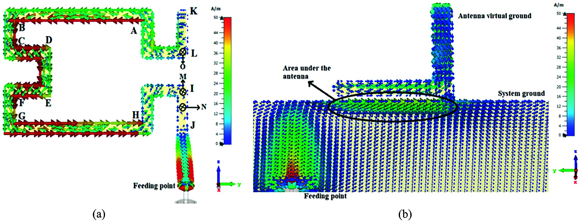
Figure 6: Simulated surface current distribution at 3.5 GHz. Antenna front side (a) and antenna back side with the main system ground (b)
The simulated results of the S-parameters for the proposed eight-element MIMO antenna system are sketched in Fig. 7. As shown in Fig. 7a, all the eight reflection coefficients of the antennas satisfy values less than –10 dB (2:1 VSWR) over all the desired bandwidth (3.4–3.6) GHz. This ensures a very good impedance matching. It can also be observed that there exists a very slight difference between the reflection coefficients of the eight antennas and that of the single antenna element (Ant1) presented in Fig. 4. This gives an indication of an acceptable mutual coupling between antennas. Because of the antennas’ similarity in the structure and the distribution along the two side-edges frame, the simulation results are also similar. So, only the transmission coefficients of the single side-edge antennas (Ant1, Ant2, Ant5 and Ant6) are presented in Fig. 7b. The transmission coefficients S51, S62, S65 are better than 12.2 dB, while S21, S61, S52 are better than 18 dB within the interested band. Therefore, good isolation is obtained without employing additional isolation elements and/or decoupling methods. To better explain the effectiveness of the proposed self-isolated antenna element in the proposed MIMO system’s good isolation, the surface current distributions of the proposed antenna system at 3.5 GHz are illustrated in Fig. 8. Two cases have been presented in this sketch where Fig. 8a shows the case when Ant1 is excited and all other antennas are terminated with 50 Ω, while Fig. 8b demonstrates the other case when Ant5 is excited and all other antennas are terminated with 50 Ω. As depicted in both figures, when either Ant1 or Ant5 is excited, the current intensity is concentrated in the region bounded inside the excited antenna area. This is the reason for good isolation of the proposed 8-element MIMO system. In this case, the desirable impedance matching and isolation are achieved without using matching circuits, additional isolation elements, and/or other decoupling methods which increases system complexity and reduces antenna efficiency. So, this is considered as the main advantage of the proposed MIMO antenna system.
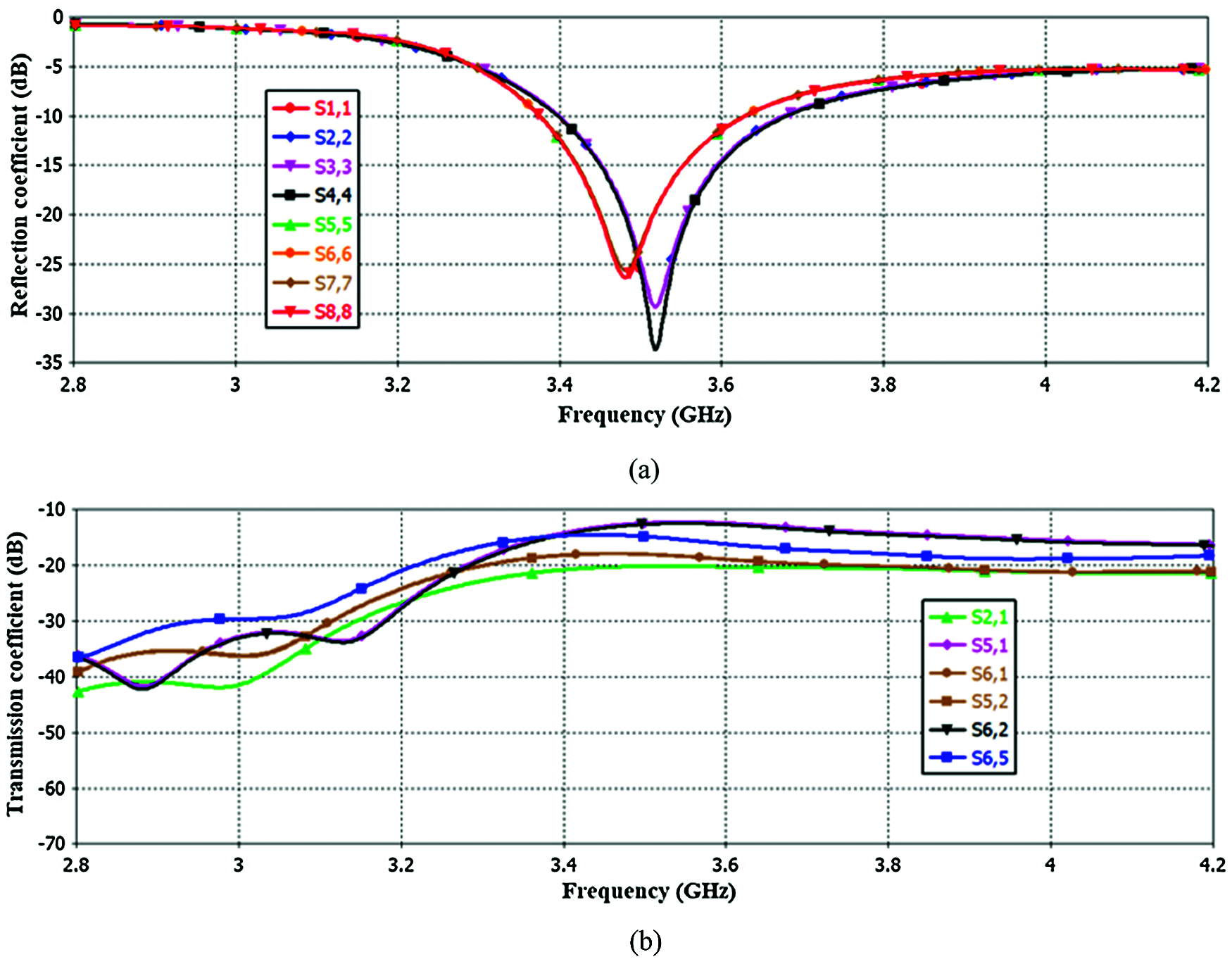
Figure 7: Reflection coefficients (a) and transmission coefficients (b)
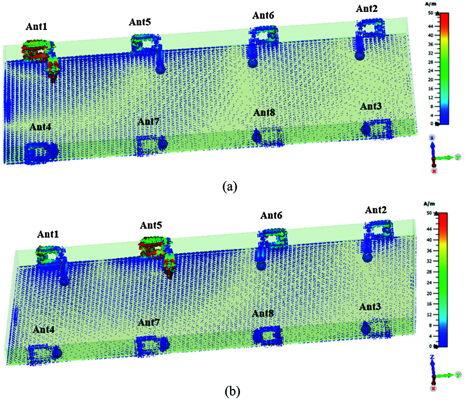
Figure 8: Surface current distribution of the proposed antenna system at 3.5 GHz with Ant1 is excited and all other antenna elements terminated by 50 Ω (a) and Ant5 is excited and all other antenna elements terminated by 50 Ω (b)
In addition to that, two cases have been studied to explain the effects of different array configurations. Due to the similarity, only the necessary S-parameters of a single side-edge are plotted in Fig. 9. In case one, the distance (D15 = D26 = 10.43 mm) is taken between the adjacent antennas (Ant1 and Ant5, Ant2 and Ant6), whereas in case two, the distance (D15 = D26 = 15.43 mm) is chosen. As can be observed in Figs. 9a and 9b, the reflection coefficients S11 and S55 do not change too much and are still satisfying the band of interest with acceptable impedance matching. The isolation (S51 in both cases) is reasonably reduced by decreasing the distance between antennas. However, the isolation is slightly reduced and is still at an acceptable value of more than 10 dB in both cases. This indicates the ability of the proposed self-isolated antenna structure in working well at different array element arrangements. So there is no need to use an impedance matching circuit or to re-optimize the antenna structure when an antenna moves from one location to another. This is one of the advantages of the proposed MIMO antenna system.
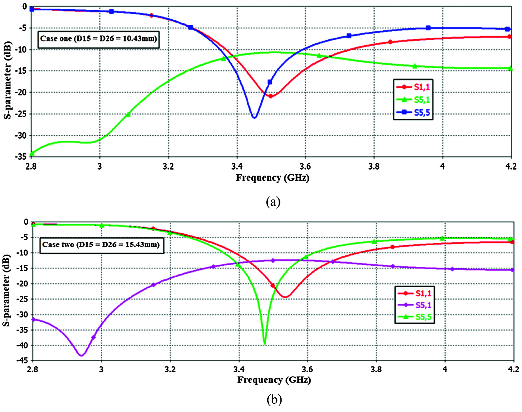
Figure 9: Simulated S-parameters of different MIMO antenna array configurations. (a) Case one (b) Case two
Fig. 10 shows all the radiation and total antenna efficiencies, which are in the range (66%–75%) and (56%–66%), respectively along the working band. The proposed self-isolated MIMO antenna system does not incur additional losses of decoupling elements or/and isolation techniques which affect the antenna efficiency performance. Thus, desirable antenna efficiencies are obtained. Fig. 11 depicts the eight antennas’ gain of the proposed MIMO system along the operating band. As observed, the maximum gains of the four antennas located at the mobile frame’s corners (Ant1, Ant2, Ant3 and Ant4) are about 4.07 dB, whereas the maximum gains of the four antennas located at the middle of the mobile frame (Ant5, Ant6, Ant7 and Ant8) are about 4.58 dB. So, they are appropriate for the 5G antenna requirement for mobile handsets. Three-dimensional and two-dimensional radiation patterns of all eight antennas at 3.5 GHz resonance frequency are displayed in Figs. 12a and 12b, respectively. Radiation pattern of Ant1 is described by (a), Ant2 is indicated by (b) and so on. As observed, the maximum gains of the antennas are in different directions, thereby indicating a desirable pattern diversity feature. Furthermore, these radiation patterns completely cover all sides of the mobile device’s mainboard, indicating a very good radiation coverage performance of the proposed antenna system.

Figure 10: Antenna efficiency

Figure 11: Antenna gain

Figure 12: Radiation patterns of all eight antennas at 3.5 GHz. (a) 3D (b) 2D
In this subsection, important parameters are evaluated and discussed to assess the potential MIMO performance of the proposed antenna array. The correlation coefficient (ρ) indicates how much the multipath communication channels are correlated or isolated (i.e., a measure of the independency) [23]. This metric refers to the correlation between the antenna radiation patterns. The square of the correlation coefficient (
where Ω defines the solid angle,
In this formula, N is the number of antennas and the antenna elements are expressed as i and j, respectively. For acceptable MIMO performance, the values of ECCs between the MIMO antennas should be less than 0.5. The smaller the ECCs, the better the MIMO system diversity performance is. The ECCs between the antennas in the proposed eight elements MIMO system are plotted in Fig. 13, which are calculated based on the E-filed radiation patterns of Eq. (1) under the hypothesis of uniform propagation channel with balanced polarization. Due to the similarity of the results, only antennas of the single side-edge frame are presented. As observed, the ECCs are all less than 0.02 in the desired band, which are far less from the accepted criteria (ECC < 0.5). So the proposed MIMO antenna system has a capability of a high diversity performance. Based on the small ECCs values, high diversity gain performance of the proposed MIMO antenna system is attained which is better than 9.9 dB in the desired band.
The Mean Effective Gain (MEG) is considered as one of the effective performance metrics for MIMO antenna systems. It can be well-defined as the ratio between the mean received power of the antenna to the total mean incident power when the antenna is moved over a random mobile environment route. MEG can be obtained from Eq. (3) below [26]:
where the cross-polarization power ratio is denoted as XPR, and
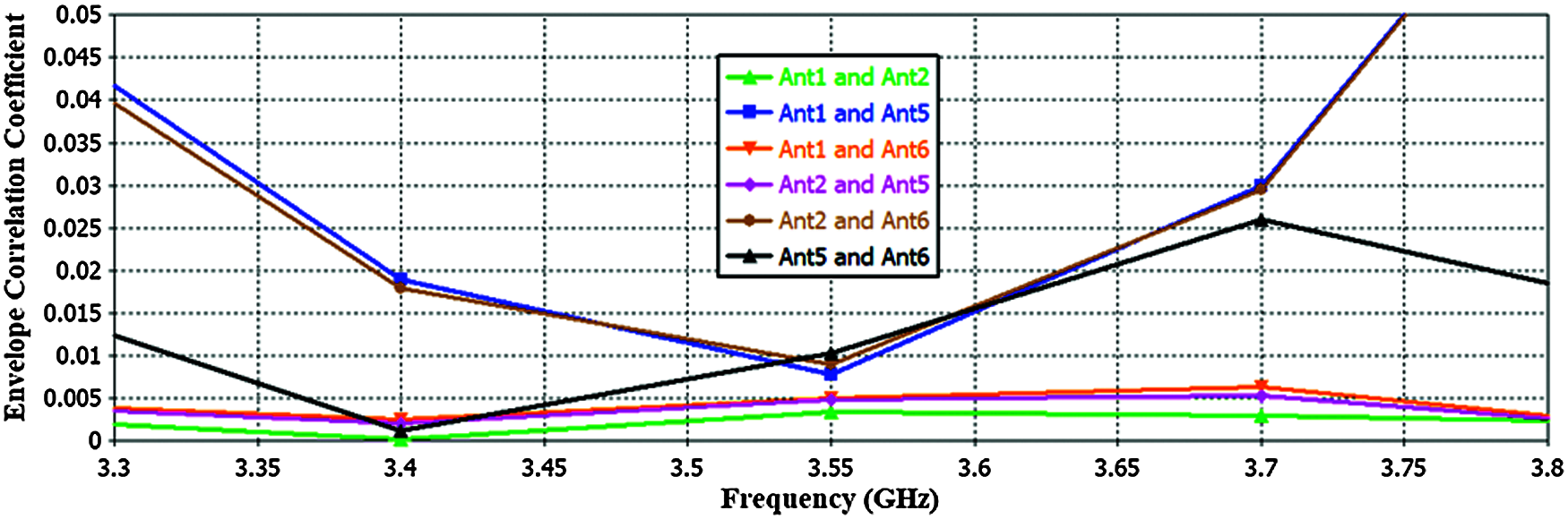
Figure 13: ECCs of the proposed system
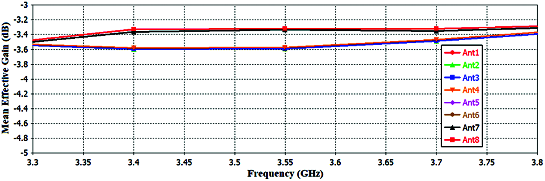
Figure 14: MEGs of the proposed eight antennas
Another significant parameter used to evaluate the multiplexing performance of the proposed MIMO antenna system is the channel capacity (CC), indicating the maximum data rate that can be achieved. It can be computed by Eq. (4) [28]:
CC is the channel capacity of the MIMO system in bits/s/Hz,
where S is the S-parameters matrix of the proposed MIMO antenna system which are obtained from the CST’s simulated results. As it can be seen in Fig. 15, the channel capacities of the proposed eight-element MIMO system are computed for different values of the Signal to Noise Ratio (SNR) based on Rayleigh fading channel environment model.
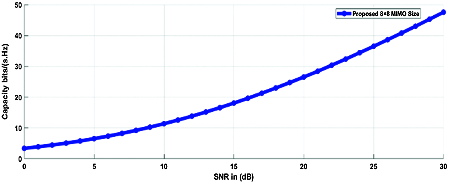
Figure 15: Simulated channel capacities of the proposed 8-element MIMO system
4 MIMO Antenna System Prototype and Measurement Results
The proposed 8-element MIMO smartphone antenna was fabricated and experimentally tested. The assembled prototype model is depicted in Fig. 16. Through the measurement process, each antenna under test (AUT) is connected to the vector network analyzer (VNA) and other antenna elements are connected to 50 Ω matched terminal loads (MTL). Due to the similarity and for the brevity, only the necessary simulated and measured S-parameters have been plotted in Figs. 17a and 17b, respectively. As observed, acceptable impedance matching and good isolation performance (better than 15 dB) are obtained by the proposed MIMO antenna system. The measured and simulated results are in good agreement. However, there are some deviations between them which may be due to fabrication tolerances, soldering effects, and/or measurement errors.

Figure 16: Fabricated prototype model of the proposed antenna (a) Perspective view (b) Back view

Figure 17: Measured and simulated S-parameters (a) Reflection coefficients (b) Transmission coefficients
Tab. 1, presents a summary for the performance comparison of the proposed eight-element MIMO antenna system with some other recent MIMO antenna systems reported for the 5G mobile phone devices. Compared with other MIMO antenna systems, the proposed one has got a smaller size and lower ECC. Good system isolation and eight antenna total efficiencies are obtained by adopting the self-isolation property where there is no additional antenna efficiency loss by other decoupling elements and/or isolation techniques. So it can be seen from the Tab. 1, that the proposed eight-element MIMO system is able to provide a massive MIMO system with a very comparable antenna and MIMO performance.

In this study, an eight-port MIMO antenna array is introduced and examined for 5G massive MIMO smartphone devices. Very good antenna miniaturization is achieved by utilizing the Hilbert fractal space-filling property. Due to the self-isolated property of the proposed antenna structure, good isolation is achieved (better than 15 dB) without using decoupling elements and/or isolation techniques. The main trait of the self-isolated property is that a single antenna can operate as a radiated and an isolated element simultaneously so that the antenna efficiencies do not decrease. The simulated and measured results of the antenna and MIMO performances obtained, as well as the structure simplicity, compactness, self-isolated property and position independency, show that the proposed eight element MIMO antenna system is a convincing candidate for the future 5G mobile phone devices.
Funding Statement: The authors received no specific funding for this study.
Conflicts of Interest: The authors declare that they have no conflicts of interest to report regarding the present study.
1. C. Z. Han, L. Xiao, Z. Chen and T. Yuan, “Co-located self-neutralized handset antenna pairs with complementary radiation patterns for 5G MIMO applications,” IEEE Access, vol. 8, pp. 73151–73163, 2020. [Google Scholar]
2. A. Zhao and Z. Ren, “Size reduction of self-isolated MIMO antenna system for 5G mobile phone applications,” IEEE Antennas and Wireless Propagation Letters, vol. 18, no. 1, pp. 152–156, 2019. [Google Scholar]
3. H. Wang, R. Zhang, Y. Luo and G. Yang, “Compact eight-element antenna array for triple-band MIMO operation in 5G mobile terminals,” IEEE Access, vol. 8, pp. 19433–19449, 2020. [Google Scholar]
4. A. J. Salim, R. S. Fyath, A. H. Ahmed and J. K. Ali, “A new fractal based PIFA antenna design for MIMO dual band WLAN applications,” in PIERS Proc., Kuala Lumpur, Malaysia, pp. 1526–1530, 2012. [Google Scholar]
5. H. Zou, Y. Li, H. Shen, H. Wang and G. Yang, “Design of 6 × 6 dualband MIMO antenna array for 4.5G/5G smartphone applications,” in Sixth Asia-Pacific Conf. on Antennas and Propagation (APCAPXi’an, China, pp. 1–3, 2017. [Google Scholar]
6. A. J. Salim, R. S. Fyath and J. K. Ali, “A new miniaturized folded fractal based PIFA antenna design for MIMO wireless applications,” in Proc. of the Int. Conf. on Information and Communication Technology, Baghdad, Iraq, pp. 36–40, 2019. [Google Scholar]
7. Y. Li, C. Sim, Y. Luo and G. Yang, “High-isolation 3.5 GHz eight-antenna MIMO array using balanced open-slot antenna element for 5G smartphones,” IEEE Transactions on Antennas and Propagation, vol. 67, no. 6, pp. 3820–3830, 2019. [Google Scholar]
8. M. Li, Y. Ban, Z. Xu, J. Guo and Z. Yu, “Tri-polarized 12-antenna MIMO array for future 5G smartphone applications,” IEEE Access, vol. 6, pp. 6160–6170, 2018. [Google Scholar]
9. C. F. Ding, X. Y. Zhang, C. D. Xue and C. Y. D. Sim, “Novel pattern-diversity-based decoupling method and its application to multi element MIMO antenna,” IEEE Transactions on Antennas and Propagation, vol. 66, no. 10, pp. 4976–4985, 2018. [Google Scholar]
10. M. Abdullah, S. H. Kiani and A. Iqbal, “Eight element multiple-input multiple-output (MIMO) antenna for 5G mobile applications,” IEEE Access, vol. 7, pp. 134488–134495, 2019. [Google Scholar]
11. W. Jiang, Y. Cui, B. Liu, W. Hu and Y. Xi, “A dual-band MIMO antenna with enhanced isolation for 5G smartphone applications,” IEEE Access, vol. 7, pp. 112554–112563, 2019. [Google Scholar]
12. N. Parchin, Y. AL-Yasir, A. Ali, I. Elfergani, J. Noras et al., “Eight-element dual-polarized MIMO slot antenna system for 5G smartphone applications,” IEEE Access, vol. 7, pp. 15612–15622, 2019. [Google Scholar]
13. W. Hu, X. Liu, S. Gao, L. Wen, L. Qian et al., “Dual-band ten-element MIMO array based on dual-mode IFAs for 5G terminal applications,” IEEE Access, vol. 7, pp. 178476–178485, 2019. [Google Scholar]
14. J. Guo, L. Cui, C. Li and B. Sun, “Side-edge frame printed eight-port dual-band antenna array for 5G smartphone applications,” IEEE Transactions on Antennas and Propagation, vol. 66, no. 12, pp. 7412–7417, 2018. [Google Scholar]
15. K. Wong, J. Lu, L. Chen, W. Li and Y. Ban, “8-antenna and 16-antenna arrays using the quad-antenna linear array as a building block for the 3.5-GHz LTE MIMO operation in the smartphone,” Microwave and Optical Technology Letters, vol. 58, no. 1, pp. 174–181, 2016. [Google Scholar]
16. Q. Kewei and G. Decheng, “Compact tunable network for closely spaced antennas with high isolation,” Microwave and Optical Technology Letters, vol. 58, no. 1, pp. 65–69, 2016. [Google Scholar]
17. J. Baek and J. Choi, “The design of a LTE/MIMO antenna with high isolation using a decoupling network,” Microwave and Optical Technology Letters, vol. 56, no. 9, pp. 2187–2191, 2014. [Google Scholar]
18. W. Hu, L. Qian, S. Gao, L. Wen, Q. Luo et al., “Dual-band eight-element MIMO array using multi-slot decoupling technique for 5G terminals,” IEEE Access, vol. 7, pp. 153910–153920, 2019. [Google Scholar]
19. J. Deng, J. Li, L. Zhao and L. Guo, “A dual-band inverted-F MIMO antenna with enhanced isolation for WLAN applications,” IEEE Antennas and Wireless Propagation Letters, vol. 16, pp. 2270–2273, 2017. [Google Scholar]
20. W. Jiang, B. Liu, Y. Cui and W. Hu, “High-isolation eight-element MIMO array for 5G smartphone applications,” IEEE Access, vol. 7, pp. 34104–34112, 2019. [Google Scholar]
21. H. Xu, H. Zhou, S. Gao, H. Wang and Y. Cheng, “Multimode decoupling technique with independent tuning characteristic for mobile terminals,” IEEE Transactions on Antennas and Propagation, vol. 65, no. 12, pp. 6739–6751, 2017. [Google Scholar]
22. A. Zhao and Z. Ren, “Multiple-input and multiple-output antenna system with self-isolated antenna element for fifth-generation mobile terminals,” Microwave and Optical Technology Letters, vol. 61, no. 1, pp. 20–27, 2018. [Google Scholar]
23. H. Aziz and D. Naji, “Compact dual-band MIMO antenna system for LTE smartphone applications,” Progress In Electromagnetics Research C, vol. 102, pp. 13–30, 2020. [Google Scholar]
24. Q. Cai, Y. Li, X. Zhang and W. Shen, “Wideband MIMO antenna array covering 3.3-7.1 GHz for 5G metal-rimmed smartphone applications,” IEEE Access, vol. 7, pp. 142070–142084, 2019. [Google Scholar]
25. S. Blanch, J. Romeu and I. Corbella, “Exact representation of antenna system diversity performance from input parameter description,” Electronics Letters, vol. 39, no. 9, pp. 705–707, 2003. [Google Scholar]
26. Z. Qin, W. Geyi, M. Zhang and J. Wang, “Printed eight-element MIMO system for compact and thin 5G mobile handest,” Electronics Letters, vol. 52, no. 6, pp. 416–418, 2016. [Google Scholar]
27. K. L. Wong, C. Y. Tsai and J. Y. Lu, “Two asymmetrically mirrored gap-coupled loop antennas as a compact building block for eight-antenna MIMO array in the future smartphone,” IEEE Transactions on Antennas and Propagation, vol. 65, no. 4, pp. 1765–1778, 2017. [Google Scholar]
28. T. Zervos, K. Peppas, F. Lazarakis, A. Alexandridis, K. Dangakis et al., “Channel capacity evaluation for a multiple-input multiple-output terminal in the presence of user’s hand,” IET Microwaves, Antennas & Propagation, vol. 1, no. 6, pp. 1137–1144, 2007. [Google Scholar]
29. A. Zhao and Z. Ren, “Wideband MIMO antenna systems based on coupled-loop antenna for 5G N77/N78/N79 applications in mobile terminals,” IEEE Access, vol. 7, pp. 93761–93771, 2019. [Google Scholar]
30. M. Li, Z. Xu, Y. Ban, C. Sim and Z. Yu, “Eight-port orthogonally dual-polarized MIMO antennas using loop structures for 5G smartphone,” IET Microwaves, Antennas & Propagation, vol. 11, no. 12, pp. 1810–1816, 2017. [Google Scholar]
31. D. Huang, Z. Du and Y. Wang, “Slot antenna array for fifth generation metal frame mobile phone applications,” Int. Journal of RF and Microwave Computer-Aided Engineering, vol. 29, no. 9, pp. 1–9, 2019. [Google Scholar]
32. M. Li, Y. Ban, Z. Xu, G. Wu, C. Sim et al., “Eight-port orthogonally dual-polarized antenna array for 5G smartphone applications,” IEEE Transactions on Antennas and Propagation, vol. 64, no. 9, pp. 3820–3830, 2016. [Google Scholar]
33. Y. Li, C. Y. D. Sim, Y. Luo and G. Yang, “Multiband 10-antenna array for sub-6 GHz MIMO applications in 5-G smartphones,” IEEE Access, vol. 6, pp. 28041–28053, 2018. [Google Scholar]
 | This work is licensed under a Creative Commons Attribution 4.0 International License, which permits unrestricted use, distribution, and reproduction in any medium, provided the original work is properly cited. |