DOI:10.32604/csse.2022.024202
| Computer Systems Science & Engineering DOI:10.32604/csse.2022.024202 | |
| Article |
Design and Analysis of Novel Antenna for Millimeter-Wave Communication
Department of Electrical Engineering, Engineering Faculty, The Hashemite University, Zarqa, 13133, Jordan
*Corresponding Author: Omar A. Saraereh. Email: eloas2@hu.edu.jo
Received: 08 October 2021; Accepted: 10 November 2021
Abstract: At present, the microwave frequency band bandwidth used for mobile communication is only 600 MHz. In 2020, the 5G mobile Communication required about 1 GHz of bandwidth, so people need to tap new spectrum resources to meet the development needs of mobile Internet traffic that will increase by 1,000 times in the next 10 years. Utilize the potentially large bandwidth (30∼300 GHz) of the millimeter wave frequency band to provide higher data rates is regarded as the potential development trend of the future wireless communication technology. A microstrip patch implementation approach based on electromagnetic coupling feeding is presented to increase the bandwidth of a dual-polarized millimeter-wave antenna. To extend the antenna unit's impedance bandwidth, coplanar parasitic patches and spatial parallel parasitic patches are used, and a 22 sub-array antenna is developed using paired inverse feed technology. The standing wave at the centre frequency of 37.5 GHz is less than 2 GHz. The antenna array's relative bandwidth is 6.13 percent, the isolation is >30 dB, the cross-polarization is −23.6 dB, and the gain is 11.5 dBi, according to the norm. The proposed dual-polarized microstrip antenna has the characteristics of wide frequency bandwidth, large port isolation, low cross-polarization, and high gain. The antenna performance meets the general engineering requirements of millimeter-wave dual-polarized antennas.
Keywords: Millimeter-wave antenna; metamaterial; electromagnetics; wireless communication
The wavelength of millimeter wave is short, and the beam width of millimeter wave radar is narrow, so it has higher angular resolution and low-elevation tracking ability. The wider available frequency band of millimeter wave can improve the range resolution of the radar system, and the improvement of the range resolution can also improve the anti-jamming capability of the millimeter wave radar [1–5].
Recently, research for the commercialization of millimeter wave 5G communication technology has been actively conducted worldwide [6–10]. 5G mobile communication technology, as well as fast data transfer speed with ultra-wideband, enable such high reliability/ultra-low latency communications, mass-connecting it to the technological evolution which is differentiated from existing 4G mobile targets [11–14]. In millimeter wave band communication, high path loss occurs between transmission and reception, unlike in the existing microwave band [15]. In order to compensate for this in the 5G millimeter wave terminal, a high-gain array antenna is used instead of the omnidirectional antenna used in 4G [16].
The millimeter wave frequency band provides many opportunities for various wireless applications, such as 35 GHz passive imaging radar [17–19], and frequency bands above 60 GHz can be used in high data rate radio line connection and sensing applications [20–22], 77 GHz automotive radar [23–25], Imager and radiator of 94 GHz [26–29] and so on. Antennas have become a key component of millimeter wave development. Millimeter wave antennas have also been used in various applications, such as broadband high-speed wireless communication systems [30–32] and automatic radar systems [33]. Millimeter wave radar systems require low profile, high gain and low cost antennas. Microstrip antennas have thin profile, small size, light weight, easy conformal, can be integrated with active devices and circuits, and can easily achieve dual-frequency and dual-polarization performance. Based on this, this paper studies a dual-polarization millimeter wave antenna scheme using microstrip antenna technology [34].
How to improve the port isolation and cross-polarization performance of dual-polarized antennas is an important research content in the field of dual-polarized antennas. There are two types of dual-polarized plane feeding methods: One is coplanar microstrip feeding, and the other is slot-coupled feeding. Among them, the advantage of using slot-coupled feeding is that the impedance bandwidth is relatively wide and it is easy to realize dual-polarization radiation characteristics. The antenna designed by Alexandre Perron et al. uses a rectangular slot with “L” antenna port isolation is −19 dB, and the cross-polarization is −18 dB [35]. The rectangular gap designed in [36] is set in a “cross” shape. This type of feed structure effectively improves the isolation performance because the feed lines of the two ports are not on the same layer of the medium, and the isolation is improved to 22 dB in the working bandwidth cross-polarization can reach −25 dB or less [37].
In this paper, a dual-polarized millimeter-wave microstrip patch antenna fed by electromagnetic coupling is designed using coplanar parasitic patches and spatially parallel parasitic patch structures to achieve the purpose of increasing the impedance bandwidth of the antenna. Using the designed unit form to form a 2 × 2 array antenna, a sub-array antenna with a millimeter wave dual-polarization microstrip structure was realized by simulation.
2 Band Widening of Slot-Coupled Microstrip Antenna
Commonly used methods to expand the bandwidth of a microstrip antenna include increasing the thickness of the substrate, reducing the dielectric constant of the substrate, loading parasitic patches, slotting, and adopting impedance matching. This article uses the method of loading parasitic patches to expand the frequency band. In order to achieve better impedance matching, a trapezoidal structure is added to the feeder. The parasitic patch can excite the frequency point adjacent to the resonant frequency of the main radiation patch, and the result is that the effective impedance bandwidth of the antenna is broadened. This phenomenon is also called double resonance technology. In this paper, parasitic patches are placed on the two radiating edges of the main radiating patch. An air layer and a dielectric layer are added to the antenna. The parasitic patches added in the vertical direction are square. The structure model of the antenna is shown in Fig. 1.
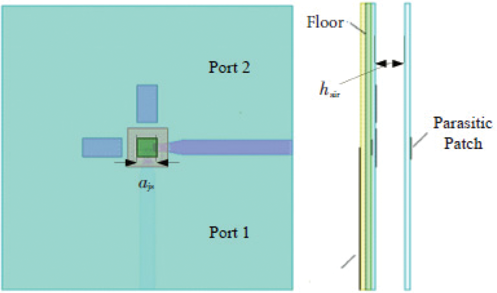
Figure 1: Microstrip antenna structure loaded with parasitic patches
The final size of the antenna is determined as the side length of the parasitic patch in the vertical direction is 1 mm, the length of the coplanar parasitic patch is 2 mm, and the width is 1.7 mm. After simulation and optimization, the frequency range of the antenna's voltage standing wave ratio ≤ 2 is about 36. 15∼43. 85 GHz, the relative bandwidth is about 20.53%. Within the working bandwidth, S21 <−20 dB, with good isolation characteristics.
3 Sub-Array Unit Design and Simulation
Based on the above design conclusions, this article studies the design and simulation of a four-unit sub-array. Fig. 2 shows two different arrays of 2 × 2 array antennas. Fig. 2a shows the paired in-phase feeding mode, that is, adjacent units in the array have the same structure and are all constant-amplitude in-phase feeding. Fig. 2b shows the paired inverting feed mode. Paired anti-phase feed technology can reduce the cross polarization of the antenna [38]. There is a mirror image structure between adjacent units, and the feed between the vertical ports or the horizontal ports is reversed, so that all the units on the dielectric board are subject to the same excitation.
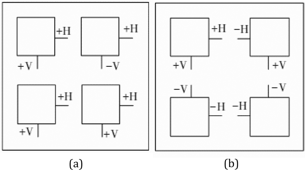
Figure 2: Different array methods of array antenna. (a) paired in-phase feed; (b) paired anti-phase feed
The authors in [39] did simulation experiments on the arrays of these two structures, and analyzed and compared the results. By comparing the directional pattern simulation results of the two, it is found that the cross-polarization level of the constant-amplitude and in-phase feed array mainly depends on the cross-polarization performance of the unit. The cross-polarization performance of the inverted feed array has been greatly improved. In [40], a detailed mathematics of a 4 × 4 array using paired inverted feeds is carried out. The theoretical analysis and radiation pattern equation of the antenna array is given. In the design, in addition to the cross-polarization performance of the antenna, the distance between the position of the parasitic patch and the unit must be considered, so the paired inverse feed technology is adopted.
Fig. 3 is the proposed structure diagram of the feed network of the slot-coupled-fed electronic array antenna designed, which uses the paired inverted feed. Since the adjacent ports of the same polarization are reversed, an inverter needs to be added to the feed network, which is the part circled in Fig. 3. The sum of the inverter feeders should theoretically be λe/2, Because the wave travels half a wavelength, the phase is just out of phase. So set λe/2 = 2.865 mm as the initial value of the inverter. In the HFSS, the feed network can be optimized and simulated separately until the phase difference between adjacent ports of the same polarization is 180°, and the final optimized result of the inverter's total feeder is 2.2 mm.
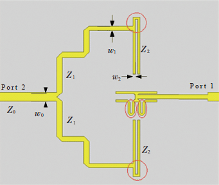
Figure 3: Proposed feeding network schematic
The design of the feed network uses a simple microstrip three-port power divider. Because the conditions of the two ports are the same, take port 1 as an example for analysis. The impedance of port 1 is Z0, Z1 = Z0
3.2 Simulation of 2 × 2 Sub-Array Antenna
3.2.1 Proposed Antenna Structure
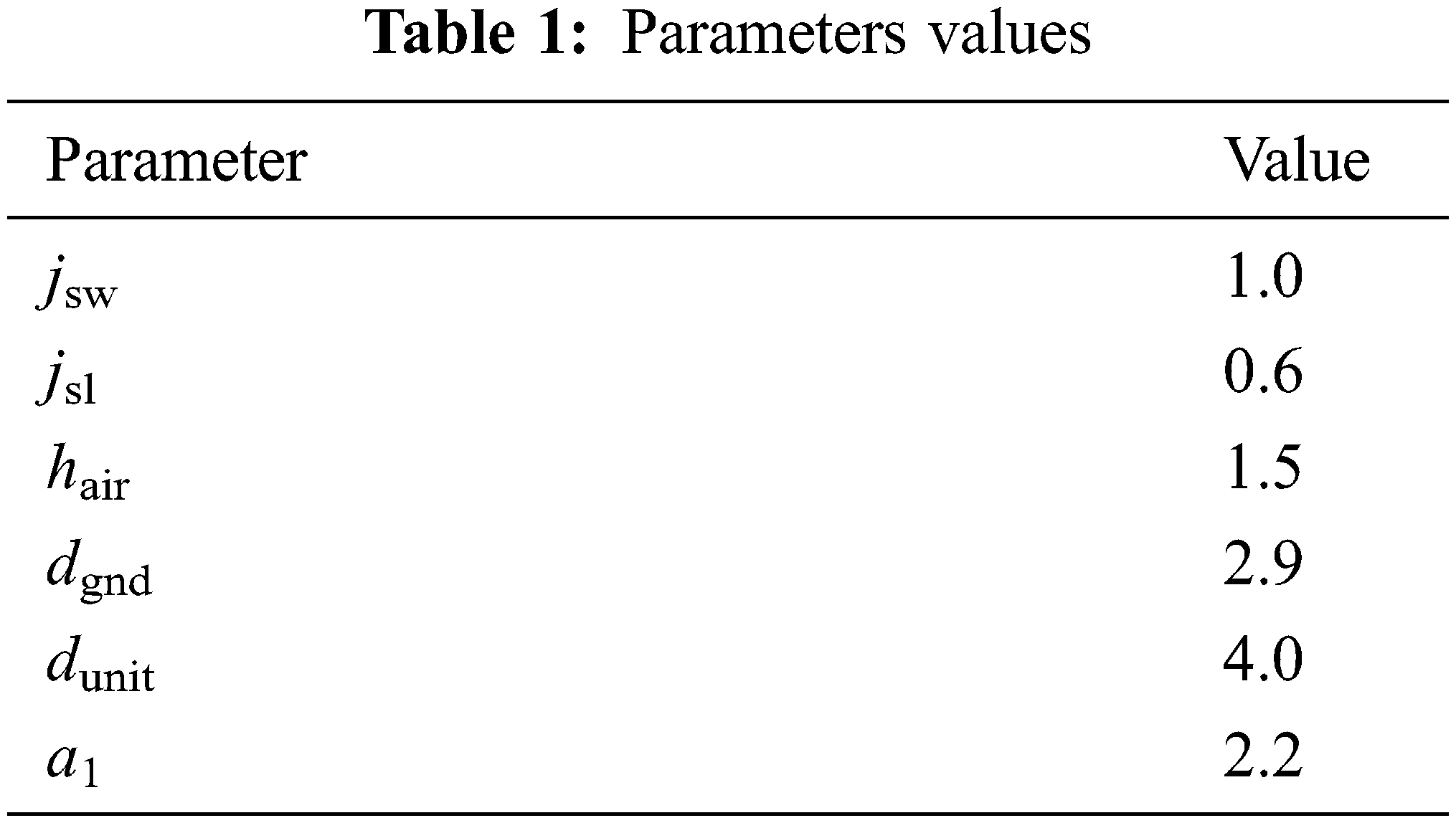
The designed slot-coupled-fed 2 × 2 sub-array antenna is shown in Fig. 4. In order to make the various indicators of the antenna meet the requirements, the unit of the antenna is adjusted, including the size of the parasitic patch, the size of the radiating patch, and the shape of the slot. First, a reflector is added behind the antenna, the purpose is to reduce the antenna's backward radiation, make the antenna one-way radiation, and increase the gain. After adding the radiating plate, the antenna mainly radiates above the dielectric plate. The distance between the 2 × 2 sub-array antenna elements is λ/2. The parameter values of the proposed antenna structure are shown in Tab. 1.
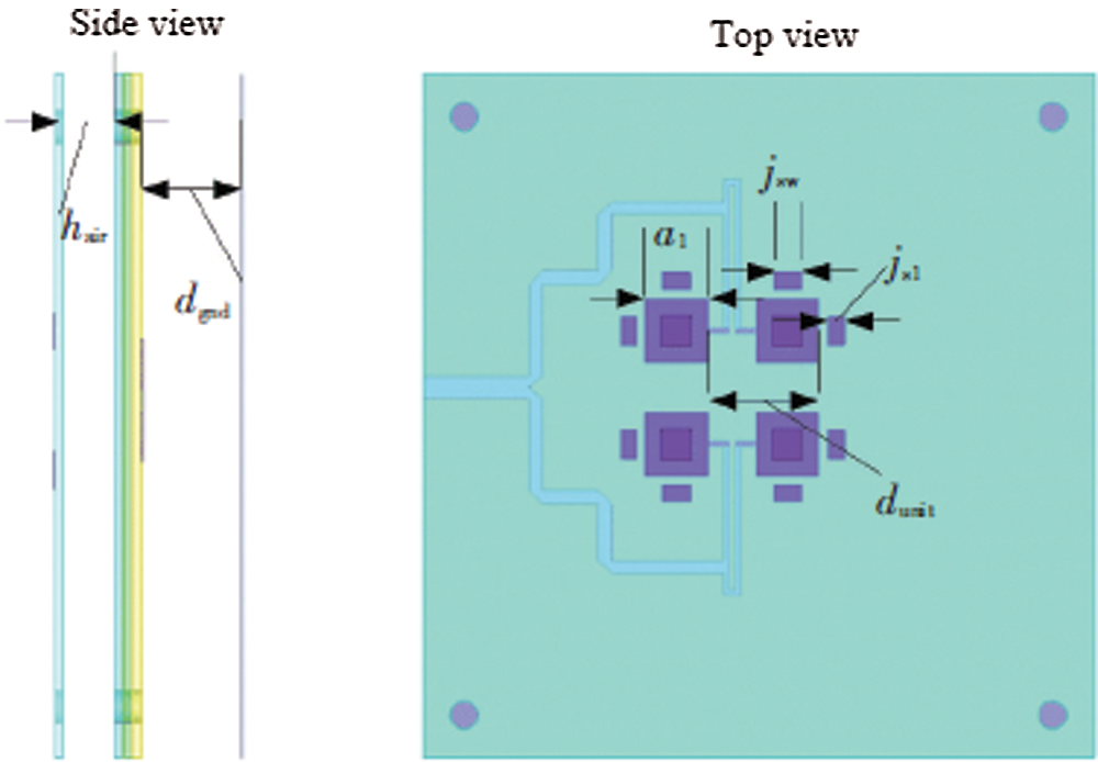
Figure 4: Proposed antenna structure
This paper uses electromagnetic simulation software CST and HFSS to simulate at the same time to verify the correctness of the design. The return loss at the two ports of the antenna obtained through multiple scan optimization is shown in Fig. 5. It can be seen that although the return loss of port 2 has been optimized to 37. 5 GHZ nearby S22 <−10 dB, but the return loss of port 1 still cannot reach 37.5 GHz. S11 <−10 dB. Due to the loss of the microstrip feed line itself, the loss of the feed network is more than the loss of a single microstrip line, which leads to the reduction of the energy coupled to the patch through the gap, making the antenna unable to form an effective resonance.
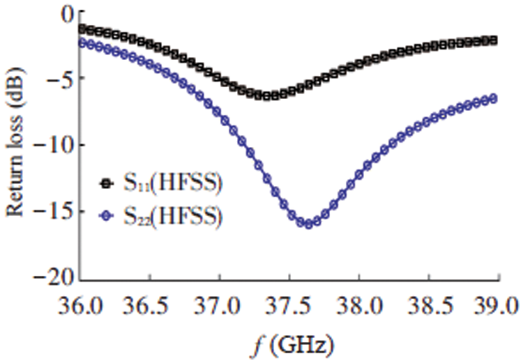
Figure 5: The port return loss of the rectangular slot array
Therefore, in the optimization process, in order to enable the slot-coupled feed port to couple more energy to the radiation patch, the original rectangular slot is changed to a T-shaped slot, as shown in Fig. 6. The parameter values of the gap structure are shown in Tab. 2. The simulation results can also prove that in the proposed array antenna, the T-slot can get better impedance matching.
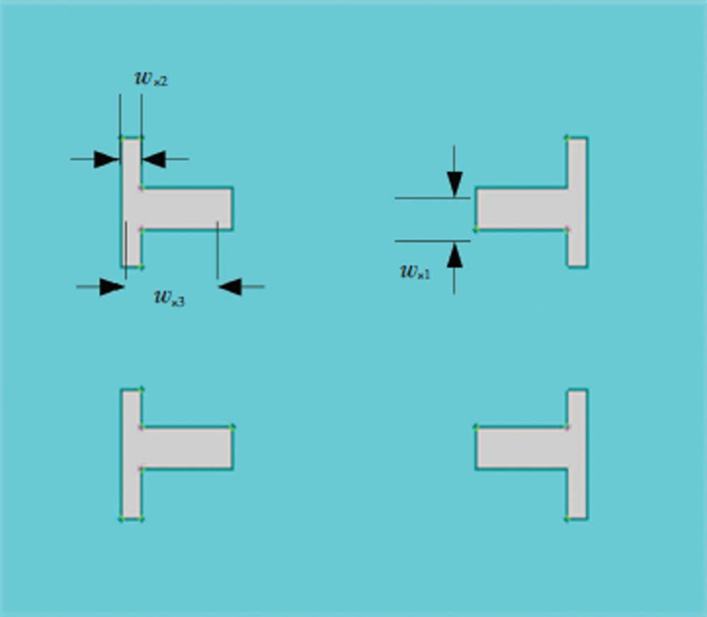
Figure 6: T-shaped gap structure

Fig. 7 shows the S parameter simulation results of the T-slot array antenna. It can be concluded that the operating frequency of the antenna is 36.6∼38.9 GHz, and the relative bandwidth is 6.13%. The bandwidth of the sub-array antenna is narrower than the bandwidth of the antenna. This is because the feed network itself is narrow-band, which leads to the narrowing of the bandwidth of the antenna. The isolation of the antenna after the array is less than −30 dB in the entire frequency band, because the feed networks of the two ports are not on the same layer, and the distance between the two polarized feed networks after the array becomes larger. The coupling between is reduced. The cross-polarization characteristics of the sub-array antenna on the E-plane and the H-plane are shown in Figs. 8 and 9 respectively. The maximum gain of the antenna at 37.5 GHz is 11.5 dBi, which is an increase of about 6.6 dB compared to the gain of a single unit. The absolute value of the cross-polarization of the antenna can reach 23 dB, and the 3 dB beam bandwidth of the antenna is about 54°.
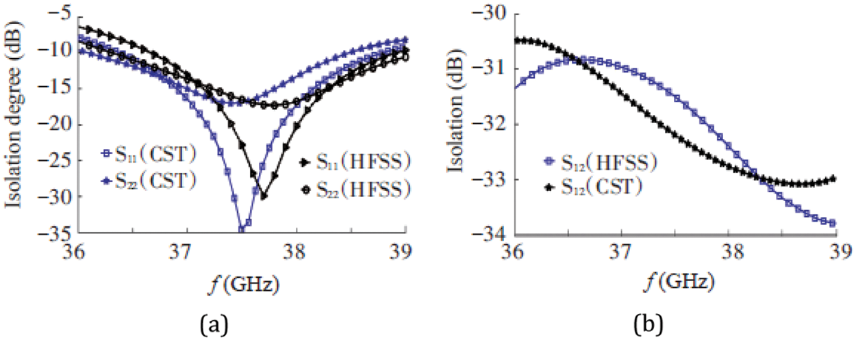
Figure 7: S-parameter simulation results of T-shaped slot array. (a) S11 and S22; (b) S12
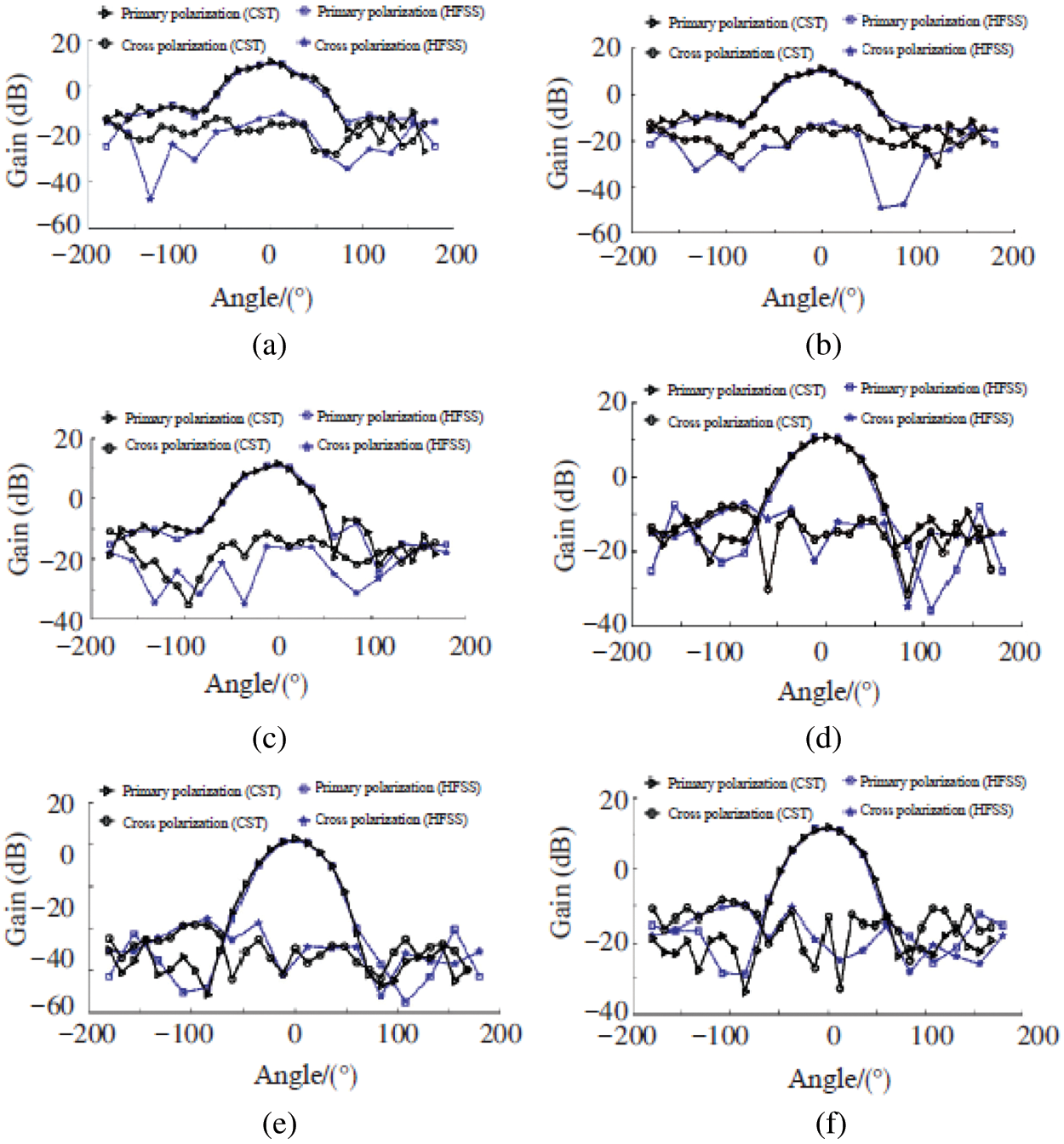
Figure 8: Directions of sub-array antenna port 1 at different frequency points (a) E-plane direction at frequency 36.5 GHz (b) E-plane direction at frequency 37.5 GHz (c) E-plane direction at frequency 38.5 GHz (d) H-plane direction at frequency 36.5 GHz (e) H side at frequency 37.5 GHz (f) H side at frequency 38.5 GHz
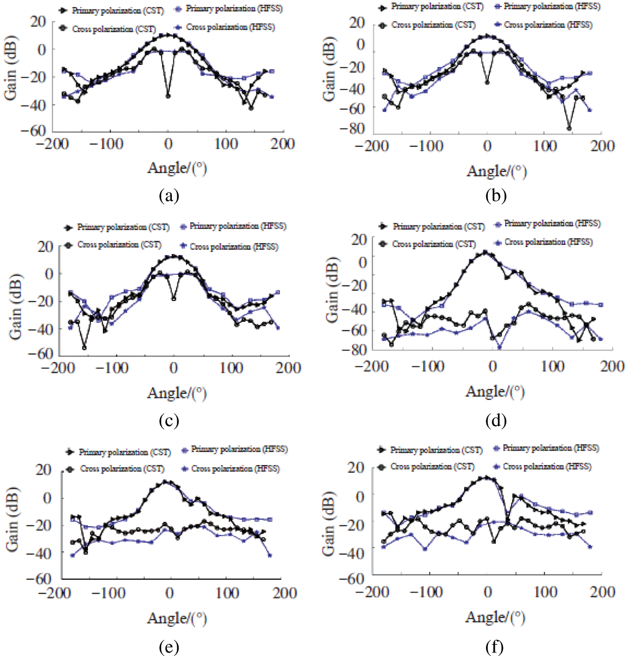
Figure 9: Directions of sub-array antenna port 2 at different frequency points (a) E-plane direction at frequency 36.5 GHz (b) E-plane direction at frequency 37.5 GHz (c) E-plane direction at frequency 38.5 GHz (d) H-plane direction at a frequency of 36.5 GHz (e) H-plane direction at frequency 37.5 GHz (f) H-plane direction at frequency 38.5 GHz
From the antenna radiation patterns when the frequencies are 36.5, 37.5, and 38.5 GHz, it can be seen that the proposed antenna design has unidirectional radiation characteristics, and the radiation patterns of the E and H planes are both smooth Most of the energy is also concentrated in the 3 dB bandwidth of the antenna.
This paper proposed the design of a dual-polarized millimeter-wave microstrip antenna based on electromagnetic coupling feed technology. Starting from technical indicators such as standing wave ratio bandwidth, port isolation and cross-polarization level, the specific design ideas and simulation optimization work are discussed. Based on the use of parasitic patch technology to achieve bandwidth expansion, a four-unit sub-array was designed and simulated, and the design of its feed network was focused on, and the simulation and optimization results of the sub-array antenna were given. At the center frequency of 37.5 GHz, the relative bandwidth of the antenna array is 6.13%, the port isolation is more than 30 dB, the cross polarization reaches −23.6 dB, and the gain is 11.5 dBi. Its technical indicators meet general engineering requirements. The research work in this paper provides an effective technical approach for the design and engineering realization of dual-polarized millimeter wave antennas.
Acknowledgement: The author would like to thanks the editors and reviewers for their precious remarks.
Funding Statement: The author received no specific funding for this study.
Conflicts of Interest: The author declare that he has no conflicts of interest to report regarding the present study.
1. S. Y. Zhu, Y. L. Li, K. M. Luk and S. W. Pang, “Compact high-gain si-imprinted THz antenna for ultrahigh speed wireless communications,” IEEE Transactions on Antennas and Propagation, vol. 68, no. 8, pp. 5945–5954, 2020. [Google Scholar]
2. O. A. Saraereh, “A novel broadband antenna design for 5G application,” Computers, Materials & Continua, vol. 67, no. 1, pp. 1121–1136, 2021. [Google Scholar]
3. R. Xu, S. Gao, B. S. Izquierdo, C. Gu and P. Reynaert, “A review of broadband low-cost and high-gain low-terahertz antennas for wireless communications applications,” IEEE Access, vol. 8, pp. 57615–57629, 2020. [Google Scholar]
4. S. L. Mohammed, M. H. Alsharif, S. K. Gharghan, I. Khan and M. Albreem, “Robust hybrid beamforming scheme for millimeter-wave massive mimo 5G wireless networks,” Symmetry, vol. 11, no. 11, pp. 1–18, 2019. [Google Scholar]
5. S. Alemaishat, O. A. Saraereh, I. Khan, S. H. Affes, X. Li et al., “An efficient precoding scheme for millimeter-wave massive mimo systems,” Electronics, vol. 8, no. 9, pp. 1–15, 2019. [Google Scholar]
6. O. A. Saraereh, I. Khan, B. M. Lee and A. Al-Bayati, “Modeling and analysis of wearable antennas,” Electronics, vol. 8, no. 1, pp. 1–12, 2018. [Google Scholar]
7. C. Wang, Y. Yao, J. Yu and X. Chen, “3d beam reconfigurable THz antenna with graphene-based high impedance surface,” Electronics, vol. 8, no. 11, pp. 1–21, 2019. [Google Scholar]
8. S. E. Hosseininejad, M. Neshat, R. Dana, M. Lemme, P. H. Bolivar et al., “Reconfigurable THz plasmonic antenna based on few-layer graphene with high radiation efficiency,” Nanomaterials, vol. 8, no. 8, pp. 1–18, 2018. [Google Scholar]
9. C. Lee and J. Jeong, “THz cmos on-chip antenna array using defected ground structure,” Electronics, vol. 9, no. 7, pp. 1–14, 2020. [Google Scholar]
10. F. Zhao, C. Zhu, W. Guo, J. Cong, C. Tee et al., “Resonant tunneling diode (RTD) terahertz active transmission line oscillator with graphene-plasma wave and two graphene antennas,” Electronics, vol. 8, no. 10, pp. 1–16, 2019. [Google Scholar]
11. S. Fajr, A. Rajawat and S. H. Gupta, “Design and optimization of THz antenna for onbody wban applications,” Optik, vol. 223, pp. 1–12, 2020. [Google Scholar]
12. S. Ullah, C. Ruan, T. Haq and X. Zhang, “High performance THz patch antenna using photonic band gap and defected ground structure,” Journal of Electromagnetic Waves and Applications, vol. 33, no. 15, pp. 1943–1954, 2019. [Google Scholar]
13. A. K. Geim and K. S. Novoselov, “The rise of graphene,” Nature Materials, vol. 6, no. 3, pp. 183–191, 2007. [Google Scholar]
14. J. Diaz and J. P. Carrier, “Microwave to THz properties of graphene and potential antenna applications,” in IEEE Int. Symp. on Antennas and Propagation (ISAP), Nagoya, Japan, pp. 239–242, 2012. [Google Scholar]
15. J. P. Carrier, M. Tamagone, J. G. Diaz and E. Carrasco, “Graphene antenna: Can integration and recofigurability compensate for the loss?,” in European Microwave Conf., Nuremberg, Germany, pp. 141–148, 2013. [Google Scholar]
16. X. Zhang, C. Ruan and J. Dai, “Reconfigurable antenna based on graphene at terahertz frequency,” in Progress in Electromagnetic Research Symp. (PIERS), Toyama, Japan, pp. 1–7, 2018. [Google Scholar]
17. N. Hussain and I. Park, “Design of a wide-gain-bandwidth metasurface antenna at terahertz frequency,” AIP Advances, vol. 25, no. 5, pp. 1–12, 2017. [Google Scholar]
18. N. Hussain, T. K. Ngyuyen, H. Han and I. Park, “Minimum lens size supporting the leaky-wave nature of slit dipole antenna at terahertz frequency,” International Journal of Antennas and Propagation, vol. 5826957, pp. 1–8, 2016. [Google Scholar]
19. N. Hussain and I. Park, “Performance of multiple-feed metasurface antennas with different numbers of patch cells and different substrate thicknesses,” Applied Computational Electromagnetics Society Journal, vol. 33, no. 1, pp. 49–55, 2018. [Google Scholar]
20. Q. Rubani, S. H. Gupta, S. Pani and A. Kumar, “Design and analysis of a terahertz antenna for wireless body area networks,” Optik, vol. 179, pp. 684–690, 2019. [Google Scholar]
21. M. E. Temmar, A. Hocini, D. Khedrouche and M. Zamani, “Analysis and design of a terahertz microstrip antenna based on a synthesized photonic bandgap substrate using BPSO,” Journal of Computational Electronics, vol. 18, pp. 231–240, 2019. [Google Scholar]
22. F. Zhao, L. Mao, W. Guo, S. Xie and C. A. Tee, “On-chip terahertz detector designed with inset-feed rectangular patch antenna and catadioptric lens,” Electronics, vol. 9, no. 6, pp. 1–14, 2020. [Google Scholar]
23. K. S. Novoselov, A. K. Geim, S. V. Morozov, D. Jiang, Y. Zhang et al., “Electric field effect in atomically thin carbon films,” Science, vol. 306, no. 5696, pp. 666–669, 2004. [Google Scholar]
24. S. A. Amanatiadis, T. D. Karamanos and N. V. Kantartzis, “Radiation efficiency enhancement of graphene THz antennas utilizing metamaterial substrates,” IEEE Antennas and Wireless Propagation Letters, vol. 16, no. 5, pp. 2054–2057, 2018. [Google Scholar]
25. M. Donelli, “A simple and efficient adaptive ISM-band antenna based on a reconfigurable optically driven parasitic structure,” Electronics, vol. 7, no. 2, pp. 1–13, 2018. [Google Scholar]
26. K. Payandehjoo and R. Abhari, “Investigation of parasitic elements for coupling reduction in multiantenna hand-set devices,” International Journal of RF and Microwave Computer-Aided Engineering, vol. 24, no. 1, pp. 1–10, 2014. [Google Scholar]
27. Z. Li, Z. Du, M. Takahashi and K. Saito, “Reducing mutual coupling of MIMO antennas with parasitic elements for mobile terminals,” IEEE Transactions on Antennas and Propagation, vol. 60, no. 2, pp. 473–481, 2012. [Google Scholar]
28. I. Nadeem and D. Y. Choi, “Study on mutual coupling reduction technique for MIMO antennas,” IEEE Access, vol. 7, pp. 563–586, 2018. [Google Scholar]
29. S. Y. Zhu, Y. L. Li, K. M. Luk and S. W. Pang, “Compact high-gain si-imprinted THz antenna for ultrahigh speed wireless communications,” IEEE Transactions on Antennas and Propagation, vol. 68, no. 8, pp. 5945–5954, 2020. [Google Scholar]
30. M. S. Rabbani and H. G. Shiraz, “Fabrication tolerance and gain improvements of microstrip patch antenna at terahertz frequencies,” Microwave and Optical Technology Letters, vol. 58, no. 8, pp. 1819–1824, 2016. [Google Scholar]
31. S. Anand, D. S. Kumar, R. J. Wu and M. Chavali, “Graphene nanoribbon based terahertz antenna on polyimide substrate,” Optk, vol. 125, no. 19, pp. 5546–5549, 2014. [Google Scholar]
32. V. P. Gusynin, S. G. Sharapov and J. P. Carbotte, “Magneto-optical conductivity in graphene,” Journal of Physics, vol. 19, no. 2, pp. 231–241, 2007. [Google Scholar]
33. L. A. Falkovsky and S. S. Pershoguba, “Optical far-infrared properties of a graphene monolayer and multilayer,” Physical Review B, vol. 76, no. 15, pp. 1–17, 2007. [Google Scholar]
34. Y. M. Lin, K. A. Jenkins, A. V. Garcia, J. P. Small, D. B. Farmer et al., “Operation of graphene transistors at gigahertz frequencies,” Nano Letters, vol. 9, no. 1, pp. 422–426, 2009. [Google Scholar]
35. G. W. Hanson, “Dyadic green's functions for an anisotropic, non-local model of biased graphene,” IEEE Transactions on Antennas and Propagation, vol. 56, no. 3, pp. 747–757, 2008. [Google Scholar]
36. L. A. Falkovsky and S. S. Pershoguba, “Optical far-infrared properties of a graphene monolayer and multilayer,” Physical Review B, vol. 76, no. 15, pp. 1–19, 2007. [Google Scholar]
37. A. Perron, T. A. Denidni and A. R. Sebak, “A low-cost and high-gain dual-polarized wideband millimeter-wave antenna,” in European Conf. on Antennas and Propagation, Berlin, Germany, pp. 3558–3561, 2009. [Google Scholar]
38. C. H. Tsao, Y. M. Hwang, F. Kilburg and F. Dietrich, “Aperture-coupled patch antennas with wide-bandwidth and dual-polarization capabilities,” in Antennas and Propagation Society Int. Symp., Syracuse, USA, pp. 936–939, 1988. [Google Scholar]
39. S. Arumugam, S. Manoharan, S. K. Palaniswamy and S. Kumar, “Design and performance analysis of a compact quad-element uwb mimo antenna for automotive communications,” Electronics, vol. 10, no. 18, pp. 1–14, 2021. [Google Scholar]
40. K. Woelder and J. Granholm, “Cross-polarization and sidelobe suppression in dual linear polarization antenna arrays,” IEEE Transactions on Antennas and Propagation, vol. 45, no. 12, pp. 1727–1740, 1997. [Google Scholar]
 | This work is licensed under a Creative Commons Attribution 4.0 International License, which permits unrestricted use, distribution, and reproduction in any medium, provided the original work is properly cited. |