DOI:10.32604/csse.2022.021693
| Computer Systems Science & Engineering DOI:10.32604/csse.2022.021693 | |
| Article |
Efficient Single-Stage Bridgeless AC to DC Converter Using Grey Wolf Optimization
1Department of Electrical and Electronics Engineering, Thangavelu Engineering College, Chennai-600097, India
2Department of Electrical and Electronics Engineering, Rajalakshmi Engineering College, Chennai-602105, India
*Corresponding Author: Prema Kandasamy. Email: premakandasamyp1@gmail.com
Received: 11 July 2021; Accepted: 01 November 2021
Abstract: Bridgeless single-stage converters are used for efficient (alternative current) AC-(direct current) DC conversion. These converters control generators, like electromagnetic meso- and micro-scale generators with low voltage. Power factor correction helps increase the factor of the power supply. The main advantage of the power factor is it shapes the input current for increasing the real power of the AC supply. In this paper, a two-switch bridgeless rectifier topology is designed with a power factor correction capability. For the proposed converter topology to have good power quality parameters, the closed loop scheme, which uses the grey wolf optimization (GWO) algorithm, is implemented. The successes of GWO encourage this research to implement GWO in the topology. The performance of the proposed topology is analyzed under different load conditions. Simulation is carried out using the MATLAB/Simulink environment, and the results are compared with those of conventional (proportional integral derivative) PID and (particle swarm optimization) PSO controllers. To validate the simulation results, a 350-W hardware prototype is implemented, and the voltage ripple, efficiency, and power factor under different load conditions are analyzed and tabulated. The comparative study clearly indicates that the proposed converter topology with a closed loop control scheme using the GWO algorithm improves the power factor to 0.9732 and reduces the voltage ripple to 0.12% with a conversion efficiency of 98.25%.
Keywords: Bridgeless; AC converter; DC converter; GWO controller; power factor
The rapid boom of renewable energy technologies has led to pollution-free power generation with reduced fuel consumption and that uses abundantly available natural resources. Though renewable energy sources have many advantages over conventional energy resources, the power quality problem arises while it is interconnected with the grid. To overcome power quality issues, passive filters were used along with power converters in olden days. However, this practice was discouraged due to additional stage requirement and the cost and over size of power conversion stages. In this paper, the power quality problem is addressed while interconnecting the AC-DC converter with the grid. To achieve the objective of the proposed work, the researchers contributed many works to the literature.
A single-stage three-level isolated power factor corrected AC/DC converter was proposed for low power applications where switches are shared between stages [1]. In this work, the output voltage is regulated with input current shaping. To have a good power factor in line voltages, the switches are triggered using the (zero volt switching) ZVS and (zero current switching) ZCS concept. Having the same switches with different switching schemes enables single-stage conversion. The result reveals that the proposed converter could achieve a 0.99 power factor with 95.2% efficiency.
The proposed converter could improve the power factor during boost or buck converter mode charging. Due to power quality problems addressed in (switched-mode power supply) SMPS supplies to personal computer had led to usage of non-isolated power factor corrected converter used at the front end of (switched mode power converter) SMPC to resolve power quality issues. To select best operating mode of front-end converter, a simulation was carried out and same was implemented on experimental prototype. The results revealed that the proposed converter could overcome the conventional converter in terms of power factor, voltage regulation and harmonic content. A power conversion interface was introduced which consist of power factor correction stage and buck converter unit.
The rest of this paper is organized as follows. Section 2 presents the related literature on the proposed model. Section 3 briefly discusses the proposed technique. Section 4 presents the results and their evaluation, and Section 5 concludes the research work.
A highly efficient soft-switched AC/DC converter, which incorporates the boost and buck converter topologies, was proposed by a previous study [2]. In the converter, the boost converter operates in discontinuous mode, ensuring power factor correction, while the buck converter operates to ensure a stable ripple-free regulated DC output voltage. This investigation concluded that the proposed concept could achieve 94.8% efficiency. 0.995 pf with 9.25%. For low power applications, an output voltage regulated with a power factor corrected AC/DC converter was proposed [3]. The loss-free resistor behavior was used in the (single-ended primary-inductor converter) SEPIC and the cuk converter to improve the power factor. To avoid distortion near the zero input current, a variable bandwidth hysteresis controller was used. The results indicate that the performance of the cuk converter is better than that of the SEPIC converter in terms of achieving the objective.
Without an input diode bridge, a single-stage dual output PFC SEPIC converter was proposed for the RMS voltage range of 85 V to 265 V [4]. To replace two individual inductors, a magnetically coupled inductor was introduced in the circuit. The proposed work could achieve 95% efficiency with a near-unity power factor and a (total harmonic distortion) THD of 14.8%. A continuous conduction mode (unified power format) UPF single-phase bridgeless buck rectifier was proposed in a previous study [5]. The proposed topology could achieve dead angle freedom at the zero crossing of the input current. A THD of less than 7% and a near-unity power factor with 94% maximum efficiency could be achieved.
An analysis was performed to explore the reason for the occurrence of high voltage stress in a single-stage power factor correction converter and provide a solution [6,7]. The previous works reported the reason under the steady state condition, but transient performance was not considered [8]. The inherent negative current feedback property in an output inductor causes voltage stress. Incorporating an auxiliary circuit into the main transformer could reduce the voltage stress during the output variation of load. A power-factor-corrected integrated battery charger was proposed for electric vehicle applications [9,10]. The charger could operate the power factor of more than 0.9 for both boost and buck operations at 48 or 192 V [11].
The multilevel AC/DC conversion stage was introduced due to low switching harmonics and with-stand capacity of passive components. The proposed conversion interface could achieve unity power factor and low harmonic distortion. For telecommunication applications, a three-level full bridge AC/DC converter was proposed and investigated by incorporating three different closed loops [12]. The results indicate that genetic-algorithm-based average current control performs better in terms of power factor, THD, and UPF without a filter requirement at the source side under disturbances in the source and load sides. A three-phase Vienna AC/DC converter with power factor correction in which (field-programmable gate array) FPGA-based emulation was implemented for generating switching pattern was proposed in a previous study [13]. In the proposed scheme, the control scheme was implemented by incorporating Hardware-in-the-Loop testing in the system, thereby increasing the accuracy. A semi-bridgeless boost rectifier was presented for power factor correction using a sliding mode controller [14]. The proposed topology consists of two boost cells operating in complementary mode. The third order harmonic component reportedly decreased. The problem raised due to two unbalanced inductors was also mitigated. To achieve high power density and efficiency, a three-level single-phase rectifier operating in one direction with the (power factor correction) PFC was presented by a previous study [15]. This topology exhibits a lower switching loss than the state of the art; the low conduction loss results in 98% maximum efficiency with 2.18% THD at 140 kHz switching frequency. A single-stage AC/DC converter was proposed with ZVS capability in all active switches [16]. The H-bridge topology was used, offering power factor correction and DC output voltage regulation. The proposed scheme could achieve 92% maximum efficiency due to the reduced losses in the magnetic reactor and transformer.
For power quality improvement, AC to DC converters were proposed on the basis of the magnetic energy recovery switch [17]. The proposed converter topology was used in high-current and low-voltage applications, such as electric vehicle charging. The proposed converter can maintain good power quality parameters in the presence of source and load disturbances, and the power factor was maintained at 0.99 with R and RL loads. To drive a (brushless DC electric motor) BLDC motor, a new AC/DC converter topology was proposed in combination with the chopper circuit, allowing the voltage boosting during discontinuous conduction and reduction during the continuous mode of operation [18].
The proposed converter has only one switch, which could supply the required real power with an improved power factor at 25 kHz switching frequency. For the BLDC motor to drive with an improved power factor, the Luo converter was proposed on the basis of single voltage sensor [19]. It was able to provide good power quality parameters with values consistent with the IEC 61000–3–2 standard with unity power factor. A forward converter capable of ZVS switching with power factor correction for the split-phase charger was proposed by a study [20]. Given the soft switching of active switches, the converter efficiency improved considerably with good power quality indices. The proposed converter was simulated and built in a lab for checking the feasibility on a real test bench, achieving the maximum efficiency of 94% with a power of 0.985.
3 Proposed GWO-Based Converter Topology
The proposed converter topology consists of two active swiches, S1 and S2, which are switched asymmetrcally as shown in the figure, which also shows no continous conduction. The switches are triggered as per the switching pattern generated and shown in Fig. 1. The pulses are generated using the phase shifted carrier (pulse with modulation) PWM technique, which reduces the switching frequency in the individual leg, and the switching angle is distributed among the switches. The rectifier bridge consist of diodes D1–D4, which assist the main switches in both the negative and postive half cycles. Inductors L1 and L2 are placed in the upper and lower arms, respectively. The load voltage is shared by capacitors C1 and C2.
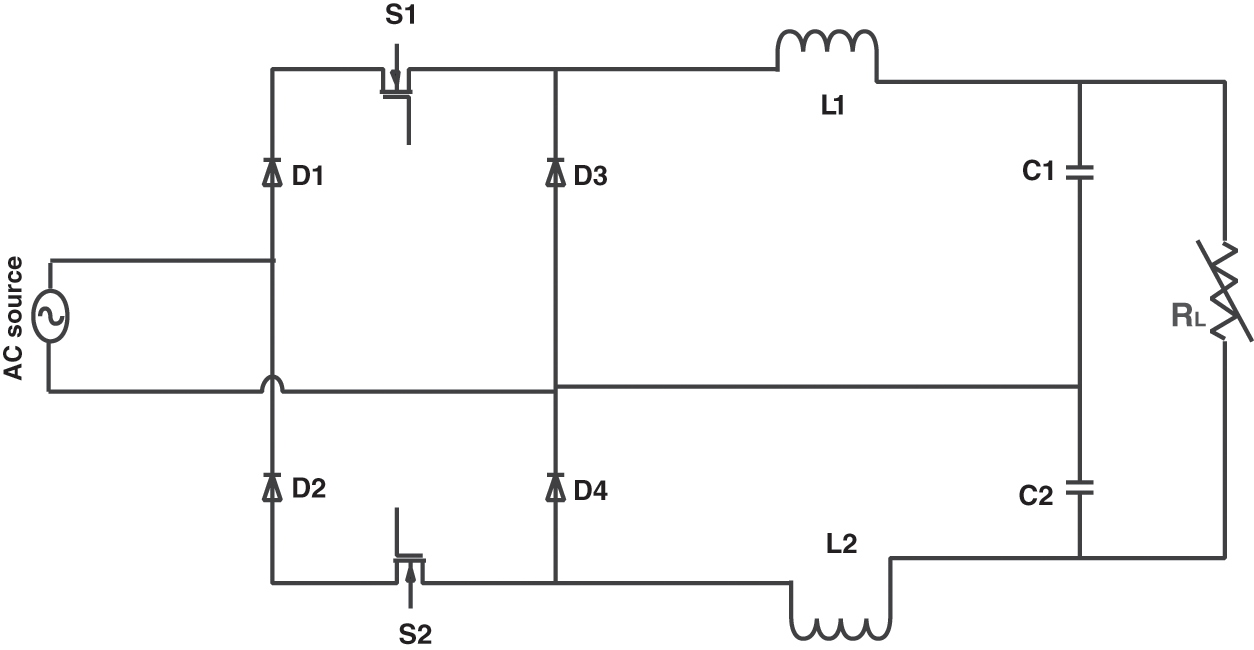
Figure 1: Proposed converter topology
Mode 1: In this mode, switch S1 is turned on, the current conduction path is shown in Fig. 2a, and the load voltage is being shared among the capacitors.
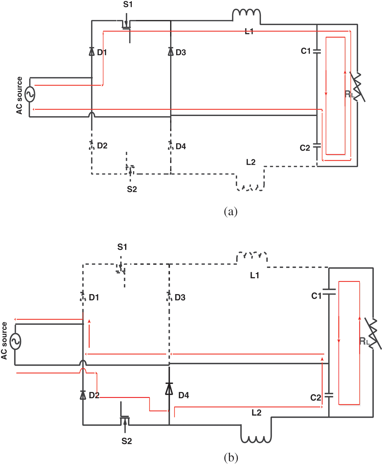
Figure 2: (a) Mode 1 (b) Mode 2
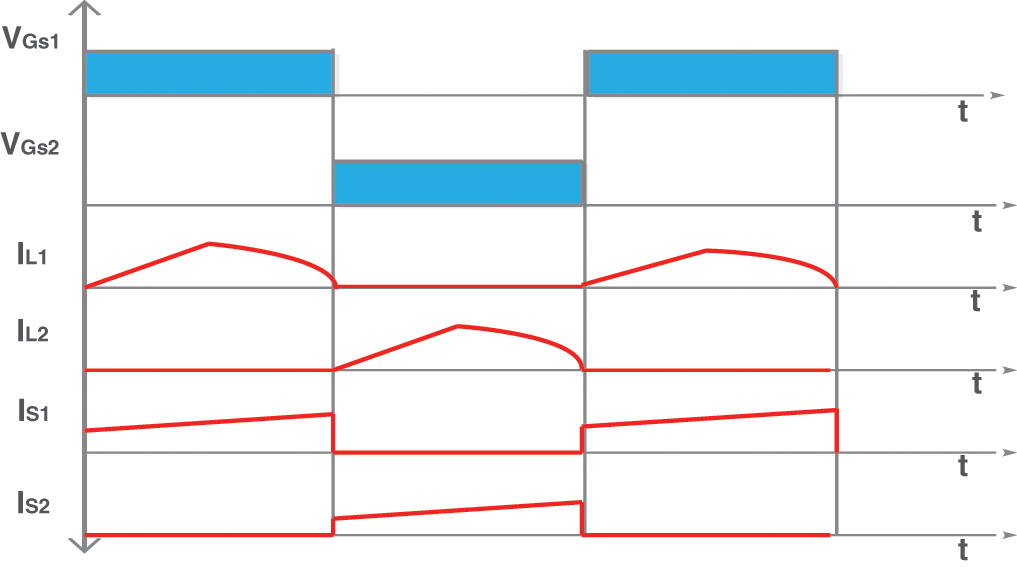
Figure 3: Theoretical key waveform
Mode 2: At the end of Mode 1, switch S1 is turned off and switch S2 is turned on. The corresponding current path is shown in Fig. 2b. During this mode, diodes D2 and D4 assist the current conduction. Both inductors are charging in this mode.
Vo1 and Vo2 are the voltages across output capacitors C1 and C2, respectively; Vin is the input RMS voltage; Po is the output power; and fs is the switching frequency.
3.2 Design of Proposed Converter
Design of inductor L1, L2: The inductor values are assumed equal, that is, L = L1 = L2, and the zero crossing dead angle zero. The inductor value can be determined using the following equation, where ΔIL indicates the input current ripple, and Vc1 indicates the voltage across output capacitor C1.
Design of output capacitor C1, C2: The output capacitor value is calculated using the following equation, assuming unity power factor. The voltage ripple is approximately equal to the difference between the input RMS voltage and the average output voltage regardless of the circuit topology. Fig. 3 shows that the theoretical key wave form of the propsoed system. Vin and Iin indicate the input RMS voltage, f1-indicates the supply frequency, and ΔVout indicates the voltage ripple.
Researchers have been using meta-heuristic algorithms in the last decades because of their simplicity and flexibility in solving non-linear problems and they need no derivative concepts and avoid local minima [21]. To overcome the drawbacks of well-known nature-inspired algorithms, such as genetic algorithm, gravitational search algorithm, and differential evolution, a new algorithm called grey wolf optimization (GWO) was proposed by Seyedali Mirjalili. GWO is inspired by the leadership and hunting behavior of wolves and their hierarchy in handling preys. To depict the encircling of a prey by wolves, the following mathematical model was established:
where
ɛ is linearly decreasing from 2 to 0 in the interval of iteration, and
To imitate the hunting behavior of wolves, the following mathematical expressions were established.
The next phase involves the exploitation and exploration of the prey. The wolves start attacking the prey when no movement is noted in the prey. To imitate this behavior, the value of ε is linearly decreased from 2 to 0. The wolves are instructed to attack the prey if
The proposed converter is simulated in the MATLAB/Simulink environment to analyze the performance of the converter using the circuit parameters listed in Tab. 2. The active switches are symmetrically triggered. The switching pattern is generated using the phase shifted carrier PWM (phase-shifted carrier pulse width modulation based) PSCPWM technique in which the switching angle is distributed to reduce the frequency. The switching pattern using the PSCPWM technique is shown in Fig. 4. The input voltage applied is 230 V AC, and the output voltage obtained is 160.5 V with a 0.12% ripple content. The source voltage, output voltage, source current, and output current waveforms are shown in Fig. 5. The conventional PID controller without a tuning gain was implemented initially, and the results are compared with those of the PSO and proposed meta-heuristic GWO controllers. Tab. 2 clearly shows that the gain tuned by the GWO controller yielded a better performance than the other two methods. The source current had a total harmonic distortion of 4.45% when delivering real power of 340.5 W and reactive power of 15.1 KVAR. The power factor of the proposed converter drastically increased to 0.9732, which is near unity, resulting in a conversion efficiency of 98.25%.
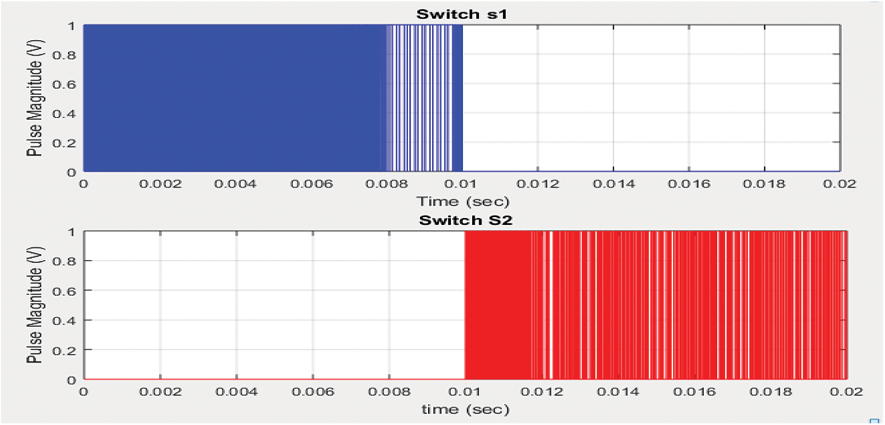
Figure 4: Switching pattern generated for switches S1 and S2
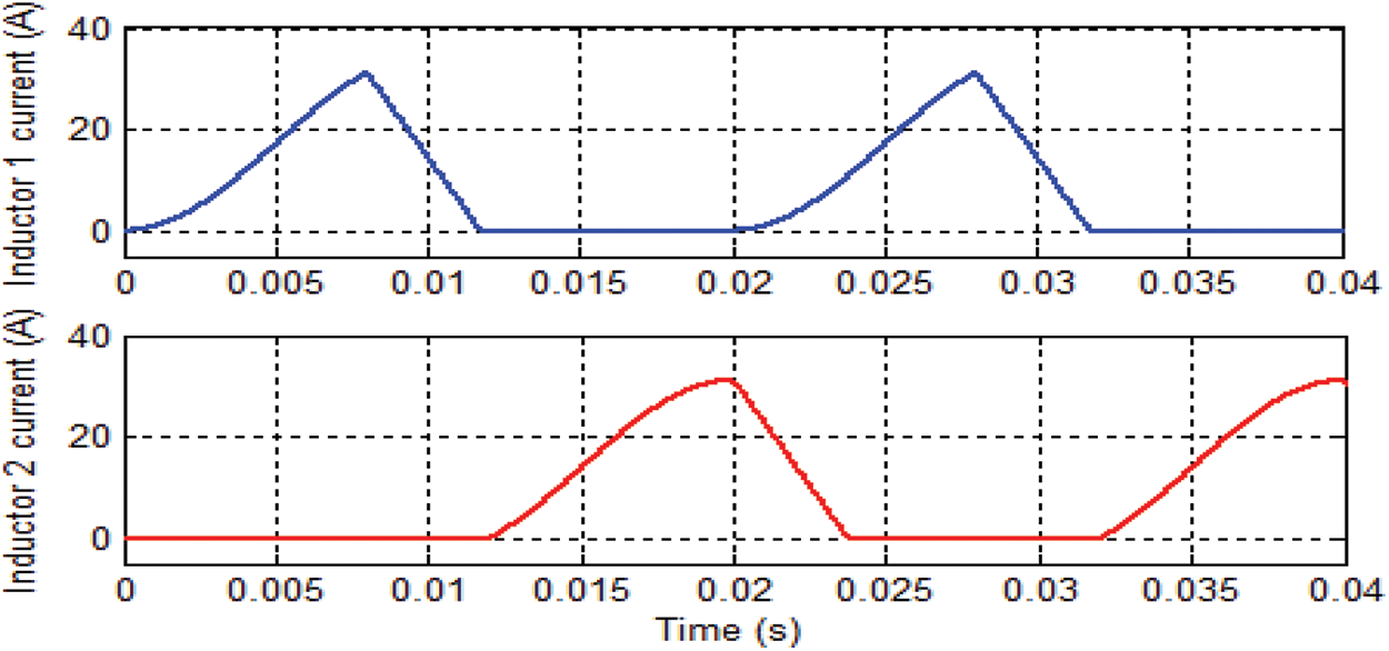
Figure 5: Inductor current IL1, IL2
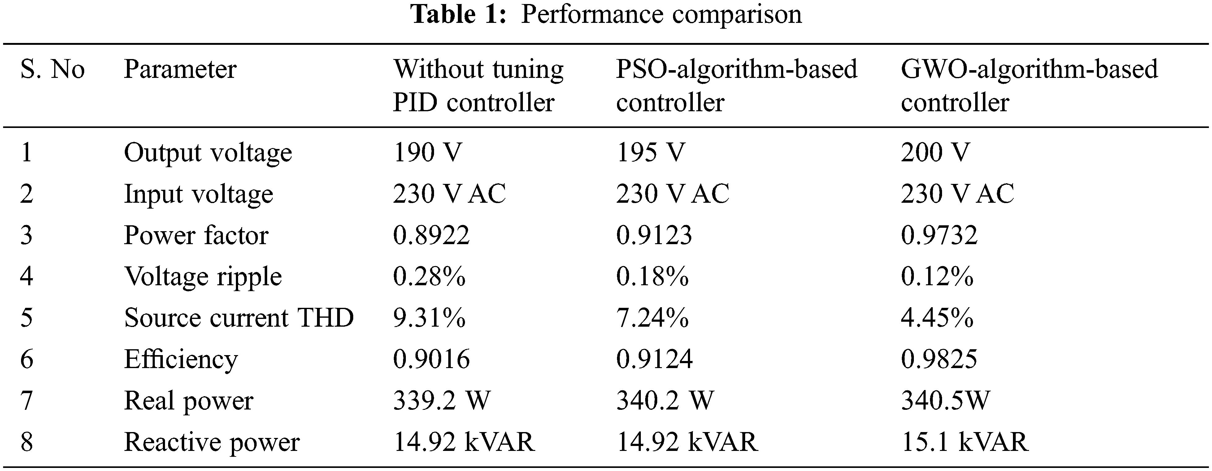
Fig. 6 indicates that the proposed converter delivers more output power with high conversion efficiency when the GWO controller is used to tune the PID controller gain than when the PSO controller is used.
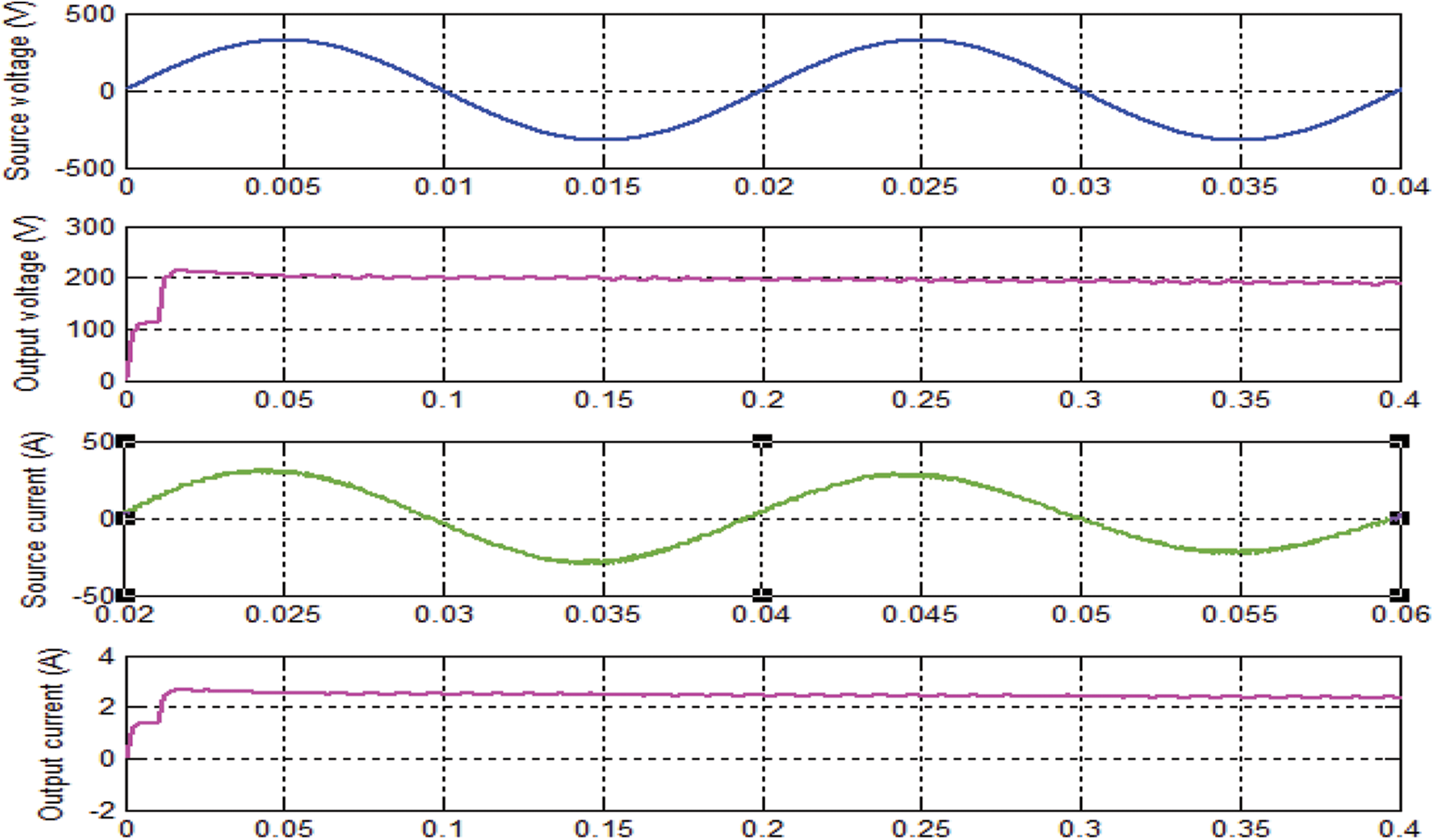
Figure 6: Source voltage, output current, source current, and output current
The performance comparison between the PID controller without gain tuning, the PSO controller, and the GWO controller is presented in Tab. 1. The source current THD window of the PID controller without gain tuning, the PSO controller, and the GWO controller is shown in Figs. 7 and 8. From the source current, the THD of the PID controller is reduced compared to those of the other two methods.
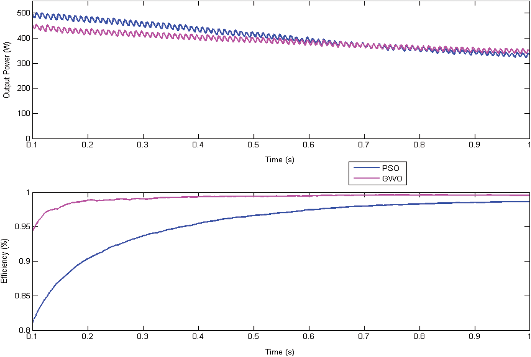
Figure 7: Output power and efficiency with respect to time
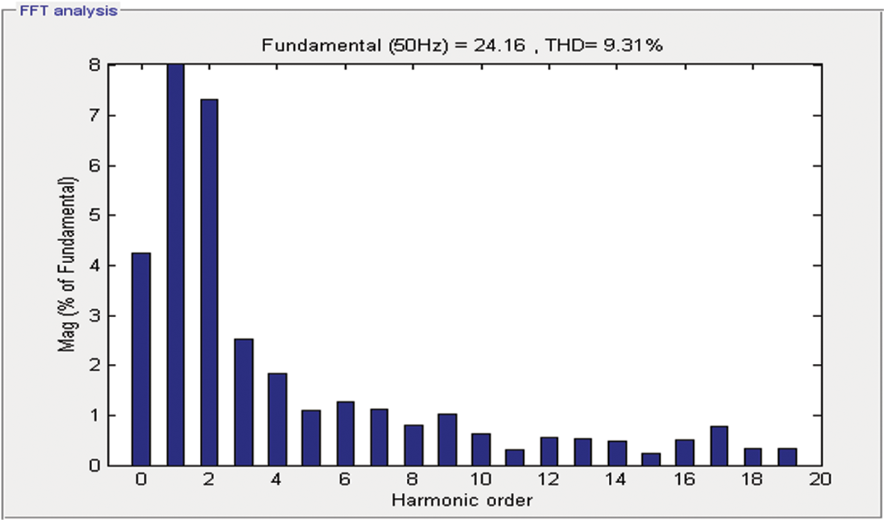
Figure 8: THD window of source current without tuning PID controller
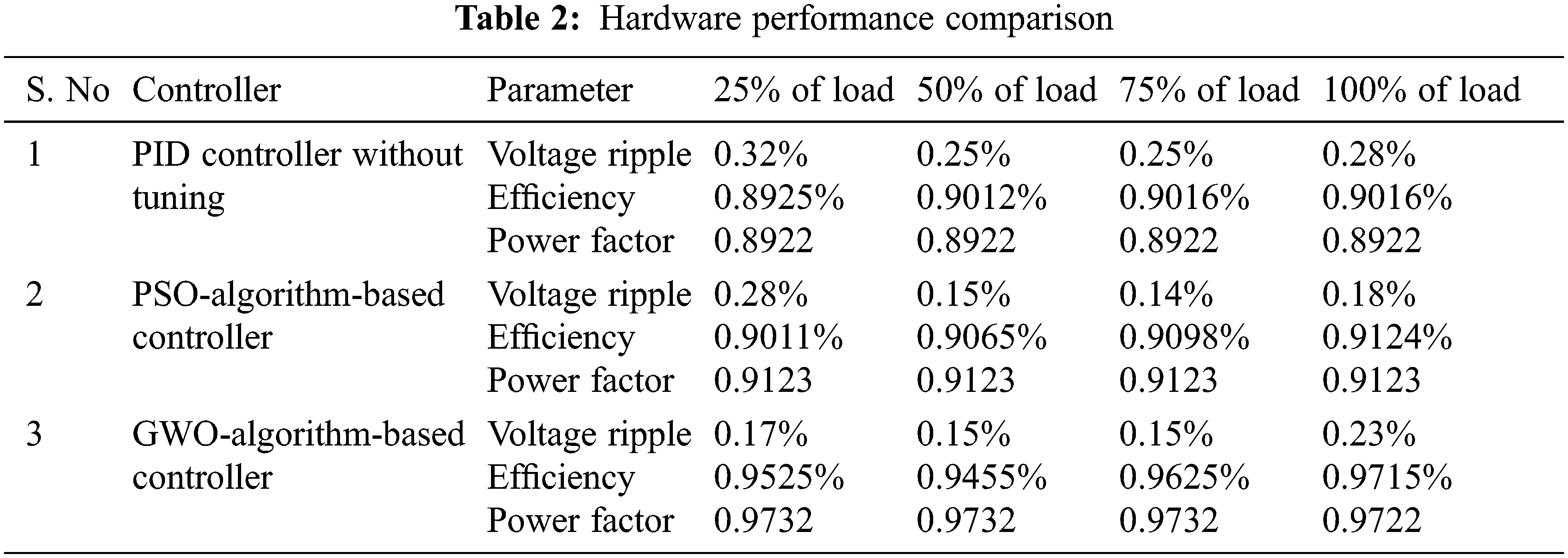
To validate the simulation results on a real test bench, the proposed 350 W–200 V topology with 20 kHZ switching frequency was constructed using the circuit components listed in Tab. 1. The performance of the proposed converter topology with a GWO controller is compared under different values of the load resistance connected to the output port. Tab. 2 indicates that the proposed rectifier can achieve 97.15% maximum efficiency at full load condition with a power factor of 0.9732, which is near unity.
4.3 Hardware Performance Comparison
The power quality parameters listed in Tab. 2 were measured using a TEKTRONIX (SMU 2450) power analyzer. The measured efficiency was 97.15%, which agrees with the simulation efficiency. The switches were triggered at 20 kHz frequency, and the pulses generated are shown in Fig. 9. The measured input voltage of 230 V AC and the current of 2.5A are shown in Fig. 10. The measured inductor current is shown in Fig. 11. The input voltage and current waveform is shown in Fig. 12. The experimental output voltage obtained was 195 V, which is near the simulation result with a 0.5% voltage ripple.
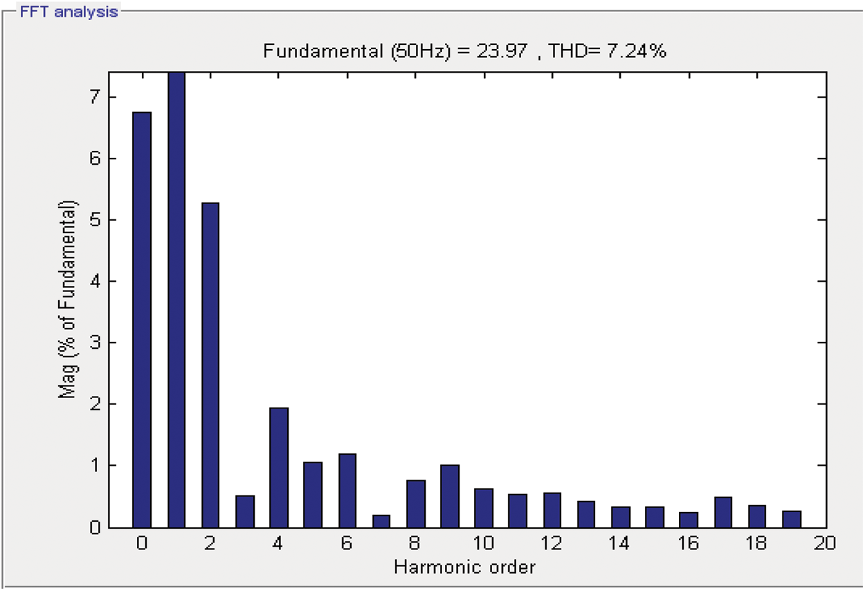
Figure 9: THD window of source current with PSO controller
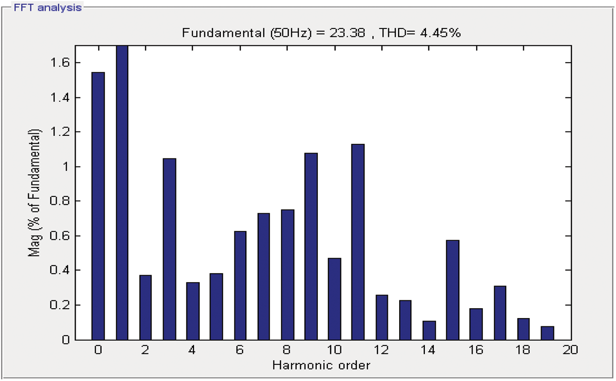
Figure 10: THD window of source current with GWO controller
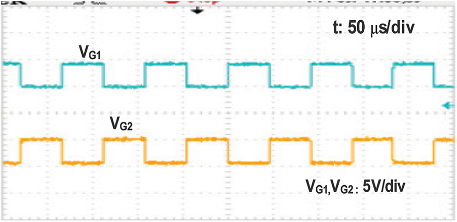
Figure 11: Gate pulses applied to switch S1, S2
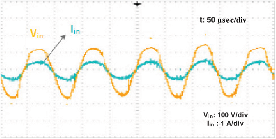
Figure 12: Input voltage and current
A highly efficient bridgeless AC/DC converter with a topology capable of power factor correction is proposed with a GWO0-based closed loop control scheme. The detailed analysis of the proposed topology and the design of the circuit parameters were discussed. Simulation was carried out using MATLAB/Simulink to analyze the power quality parameters of the proposed topology, and the results were compared with those of the conventional and PSO controllers. The prototype hardware of 350 W was implemented in the laboratory under various load conditions. The power quality parameters of the proposed scheme, like voltage ripple, power factor, source current THD, and efficiency, under different load conditions are better than those of the other two closed loop control schemes. In the future, the firefly and butterfly optimization techniques of swarm intelligence can be tested and the power coversion can improved.
Funding Statement: The authors received no specific funding for this study.
Conflicts of Interest: The authors declare that they have no conflicts of interest to report regarding the present study.
1. S. Dusmez, X. Li and B. Akin, “A fully integrated three level isolated single stage PFC converter,” IEEE Transactions on Power Electronics, vol. 30, no. 4, pp. 2050–2062, 2015. [Google Scholar]
2. C. Chang, E. Chang, H. Cheng and B. Yang, “An integrated high power factor converter with ZVS transition,” IEEE Transactions on Power Electronics, vol. 31, no. 3, pp. 2362–2371, 2016. [Google Scholar]
3. M. Bodetto, A. El Aroudi, A. C. Pastor, J. Calvente and L. Martínez salamero, “Design of AC–DC PFC high order converters with regulated output current for low power applications,” IEEE Transactions on Power Electronics, vol. 31, no. 3, pp. 2012–2025, 2016. [Google Scholar]
4. C. Shen and S. Yang, “Dual output single stage bridgeless SEPIC with power factor correction,” Journal of Power Electronics, vol. 15, no. 2, pp. 309–318, 2015. [Google Scholar]
5. G. Cao and H. Kim, “Improved bridgeless interleaved boost PFC rectifier with optimized magnetic utilization and reduced sensing noise,” Journal of Power Electronics, vol. 14, no. 5, pp. 815–826, 2014. [Google Scholar]
6. Y. Lai and Z. Su, “New integrated control technique for two stage server power to improve efficiency under the light load condition,” IEEE Transactions on Industrial Electronics, vol. 62, no. 11, pp. 6944–6954, 2015. [Google Scholar]
7. M. Narimani and G. Moschopoulos, “A new interleaved three-phase single-stage PFC AC-DC converter,” in Proc. IECON, Quebec, Canada, pp. 92–97, 2012. [Google Scholar]
8. D. D. Lu, “High voltage stress in single phase single stage PFC converters: Analysis and an alternative solution,” IEEE Transactions on Industrial Electronics, vol. 63, no. 1, pp. 133–143, 2016. [Google Scholar]
9. Y. I. Chenliu, T. Huachen and J. Peiheng, “Integrated battery charger with power factor correction for electric-propulsion systems,” IET Electric Power Applications, vol. 9, pp. 229–238, 2016. [Google Scholar]
10. S. Singh, B. Singh, G. Bhuvaneswari and V. Bist, “Power factor corrected zeta converter based improved power quality switched mode power supply,” IEEE Transactions on Industrial Electronics, vol. 62, no. 9, pp. 5422–5433, 2015. [Google Scholar]
11. W. Jinnchang, J. Hurng and J. Jyun, “Single phase multi-level AC–DC power conversion interface,” IET Power Electronics, vol. 9, pp. 1–8, 2015. https://doi.org/10.1049/ietpel.2015.0143. [Google Scholar]
12. S. Vadivu and K. R. Ramaprabha, “Investigation on operating characteristics in three level full bridge AC–DC converter using different control strategies for telecom,” Journal of Electrical Engineering & Technology, vol. 15, pp. 1217–1230, 2020. [Google Scholar]
13. G. Aiello, M. Cacciato and G. Scarcella, “Real-time emulation of a three-phase Vienna rectifier with DC voltage control and power factor correction,” Electrical Engineering, vol. 102, pp. 97–106, 2020. [Google Scholar]
14. A. Marcos, E. Vidalidiarte, A. Cidpastor and L. Martínez Salamero, “Loss free resistor based power factor correction using a semi bridgeless boost rectifier in sliding mode control,” IEEE Transactions on Power Electronics, vol. 30, no. 10, pp. 5842–5853, 2015. [Google Scholar]
15. A. D. B. Lange, T. B. Soeiro, M. S. Ortmann and M. L. Heldwein, “Three level single phase bridgeless PFC rectifiers,” IEEE Transactions on Power Electronics, vol. 30, no. 6, pp. 2935–2949, 2015. [Google Scholar]
16. S. Maekawa Sari, T. Shunsuke, M. Hiroshi Nakazawa, Y. Usami and Y. Kusaka, “The proposal of isolated single stage AC-dC converter,” Electrical Engineering, vol. 204, pp. 908–917, 2018. https://doi.org/10.1002/eej.23093. [Google Scholar]
17. A. Berigai Ramaiaha, R. Maurya and S. R. Arya, “Magnetic energy recovery switch–based power quality AC DC converters,” International Transactions on Electrical Energy Systems, 2017, pp. e2350. https://doi.org/10.1002/etep.2350. [Google Scholar]
18. R. Meena and P. Premalatha, “Analysis of bridgeless converter model for power factor correction,” Computers Electrical Engineering, vol. 87, 2020. https://doi.org/10.1016/j.compeleceng.2020.106785. [Google Scholar]
19. S. Bhim and B. Vashist, “Power quality improvements in power factor correction luo converter fed brushless direct current motor drive: A PFC based BLDC motor drive,” International Transactions on Electrical Energy Systems, vol. 25, no. 5, 2014. https://doi.org/10.1002/etep.1882. [Google Scholar]
20. C. Taotsai, T. Chunliang, Y. Chekuo and Y. Changl, “An improved forward converter with PFC and ZVS features for split phase charger applications,” Computer and Electrical Engineering, vol. 51, pp 291–303, 2016. [Google Scholar]
21. S. Mirjalili, S. Mohammad Mirjalili and A. Lewis, “Grey wolf optimizer,” Advances in Engineering Software, vol. 69, pp. 46–61, 2014. https://doi.org/10.1016/j.advengsoft.2013.12.007. [Google Scholar]
 | This work is licensed under a Creative Commons Attribution 4.0 International License, which permits unrestricted use, distribution, and reproduction in any medium, provided the original work is properly cited. |