DOI:10.32604/csse.2022.022927
| Computer Systems Science & Engineering DOI:10.32604/csse.2022.022927 | |
| Article |
Modeling and Experimental Verification of Electric Vehicles Off-Grid Photovoltaic Powered Charging Station
1Department of Electrical Engineering, College of Engineering, Taif University, Taif, 21944, Saudi Arabia
2Department of Electrical Engineering, Faculty of Engineering, University of Tabuk, Tabuk, 47913, Saudi Arabia
3Renewable Energy & Energy Efficiency Center (REEEC), University of Tabuk, Tabuk, 47913, Saudi Arabia
4Department of Electrical Power, Faculty of Engineering, Cairo University, Cairo, 12613, Egypt
*Corresponding Author: Essam Hendawi. Email: essam@tu.edu.sa
Received: 23 August 2021; Accepted: 25 October 2021
Abstract: With the increasing development of EVs, the energy demand from the conventional utility grid increases in proportion. On the other hand, photovoltaic (PV) energy sources can overcome several problems when charging EVs from the utility grid especially in remote areas. This paper presents an effective photovoltaic stand-alone charging station for EV applications. The proposed charging station incorporates PV array, a lithium-ion battery representing the EV battery, and a lead-acid battery representing the energy storage system (ESS). A bidirectional DC-DC converter is employed for charging/discharging the ESS and a unidirectional DC-DC converter is utilized for charging the EV battery. The proposed controllers achieve maximum power extraction from the PV and regulate the DC-link voltage. It also controls the voltage and current levels of both the ESS and the EV during the charging/discharging process. The study has been applied to two cases with different power levels. Analysis, simulation, and implementation of the proposed system are presented. A 120 W laboratory prototype is carried out to verify the system performance, experimentally. Design guides for higher power levels are proposed to help in choosing the proper parameters of the converters. Both the simulation and experimental results are matched and verify the high performance of the proposed system.
Keywords: Electric vehicle; lithium-ion battery; lead-acid battery; photovoltaic; microcontroller; charging station
Recently, EVs are going to replace the classical internal combustion engine (ICE) vehicles [1,2]. This is based on the many advantages of EVs over ICEs such as higher energy efficiency, lower noise, and lower maintenance than the ICE. Moreover, EVs give many benefits to public health and are considered environmentally-friendly vehicles. Nevertheless, the EV battery charging operation yet has many barriers such as the charging station’s infrastructure, the battery charging time, and the impact of these stations on the utility grid. The fast-charging approaches can be utilized to reduce the charging time to minutes [3–5]. However, these charging stations are connected to the utility grid that is affected adversely when a high number of stations are online. Many problems are generated such as excessive overload, voltage instability, and voltage variation [6–8]. One of the solutions to overcome these problems is promoting the utility grid however this requires extensive costs. Recently, energy storage systems (ESS) are integrated to the EV charging station [9–11] to reduce the utility demand performance. This prevents utility grid overloading while the EV is being charged.
If the EV charging stations are supplied mainly from the utility grid, the concept that the EV is an environment-friend could not be accepted. Commonly, the utility grids are utilizing fossil fuels to generate the electricity. To ensure the better environmental impacts of the EV, renewable energy sources must be used in the charging stations. However, these sources are characterized by its intermittent nature. The ESSs can be used with these sources to store energy and charge EVs when needed.
The common renewable energy sources used for the EV charging stations are the PV and wind systems. However, the PV systems have many advantages such as the high efficiency and simplicity. Therefore, it is more appealing for EV charging stations. In literature, there are some research have been proposed for the EV charging stations utilizing PV energy [12,13]. Reference [14] has introduced a high-energy charging station using a two-quadrant converter supplied by PV energy. However, the introduced charging station could not be used for AC charging. An EV charging station utilizing PV array and a multiport converter has been suggested in [15]. But the harmonic distortion of the charging-station current. A z-source converter is utilized to interface the PV energy to the grid and supply an EV charger has been introduced in [16]. The charging station gave better performance but it could not work in the off-grid mode. Reference [17] has introduced a PV-powered EV charging station that the ESS management has been optimized. An optimization of the EV charging-stations scheduling has been proposed by [18]. An EV charging station powered by PV array with an ESS has been presented by [19]. The ESS showed a good support for the system during high demands. The authors in [20] presented an analysis and evaluation of a grid-connected electric vehicle charging station (EVCS) powered by a PV solar system and a pack of batteries as a storage system. The authors also gave only a simulation study and did not introduce the details of controllers. They also focused on the simulation of the system. The authors in [21] presented also a theoretical study focusing on the power management and current scenario of a solar-powered EV charging station with ESS. Additional grid support is also considered to avoid power interruption in the charging station. A PV based off-Grid charging station for EV is presented by the authors in [22]. However, the authors focused on the simulation study of the system without mathematical verifications. In addition, the PV panels operate for several periods without achieving maximum power point operation.
In this paper, an efficient EV charging station supplied from a PV panel and operates in the off-grid mode is proposed. The proposed system incorporates a PV array, a lithium-ion battery representing the EV battery, and a lead-acid battery representing the energy storage system (ESS). Also, a bidirectional DC-DC converter is employed for charging/discharging the ESS and a unidirectional DC-DC converter is utilized for charging the EV battery. The proposed control system includes three controllers. Each controller has two nested loops. One of the controllers is used to control the charging and discharging of a lead-acid battery pack that represents the ESS. Another controller is utilized to regulate the charging process of the EV battery (lithium-ion battery). The power extracted from the PV panels is always maximized to meet the required energy of the EV battery and store the excessive energy in the lead-acid battery. Design guides for selecting the suitable parameters of the converters are proposed for the low power case of study and for any higher power levels of the charging station. Modeling, analysis, and simulation of the system are presented including two cases: low power (120 W) and high power (3 kW) charging systems. Simulation results in both cases of study and experimental results in a laboratory prototype are very close and verify the effectiveness of the proposed system. A single-chip PIC18F4550 microcontroller is utilized to realize the operation of controllers and generate the control signals of the power switches, experimentally. The system is tested successfully for 120 W and 3 kW power levels. The results show that the system controllers track their references perfectly. Also, the ESS compensates for the drop in the PV energy at low insolation states and keeps the EV battery charge continuously.
The paper structure is as follows. Section 2 presents the proposed system description. Modeling of the system has been described in Section 3. The system controllers are introduced in Section 4. Simulation results are presented in Section 5. Design guides for higher power levels are proposed in Section 6. Experimental verification has been proposed in Section 7 and finally, Section 8 comes with the conclusions.
The proposed system, shown in Fig. 1, is a standalone EVCS, which is powered by a PV panel. The main power source for the system is the PV unit that is normally connected to a DC power regulating capacitor [23]. A boost converter is cascaded to the PV output terminals. The function of the boost converter is to manage the maximum power point tracking (MPPT) condition of the PV panel and provide a voltage level matching between the PV and the system DC bus. The DC bus voltage is regulated through the controllers of charging/discharging the storage battery. The boost converter output terminals are the system DC bus that is linked to the EV charger input. The EV charger is a one-quadrant buck converter. Also, the storage system, lead-acid batteries connected through a two-quadrant DC/DC converter, is linked to the DC bus.
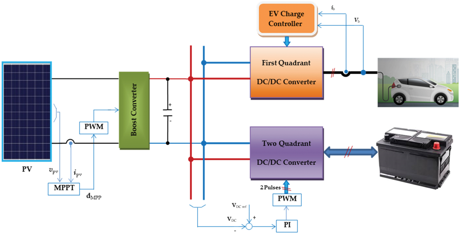
Figure 1: The proposed PV-powered EVCS with the battery storage system
3 System Modelling and Analysis Layout
Generally, the first step for any research is the modeling of the system. The system model is an important foundation for simulation, implementation, and controllers’ design. The mathematical model assumes that the system has no losses, no voltage drops and leakage currents, and no snubber circuits. Nevertheless, the computer simulations do not use those assumptions. The following paragraphs will explain the model of each part of the proposed system.
The dynamic model of the PV panel is represented by the circuit shown in Fig. 2 [24,25]. The current source value (IS) represents the short circuit current of the PV panel. The resistors (rp, rs) are the model parallel and series resistances. Relations between the model parameters are well-known in the literature [24,25].
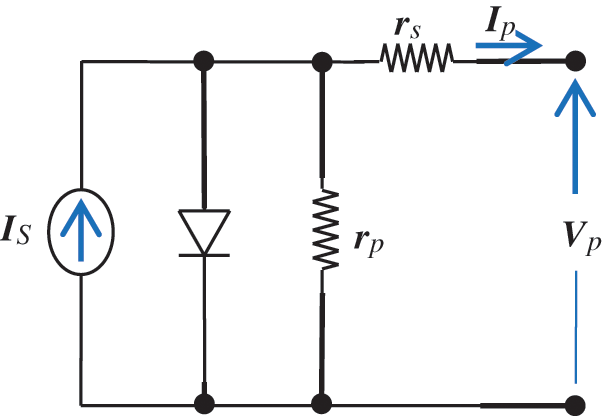
Figure 2: Circuit model of the PV array
The system converters circuit diagram is shown in Fig. 3. The analysis of the two-quadrant converter applied to the storage lead-acid battery “B1” is presented so that the converter parameters can be designed.
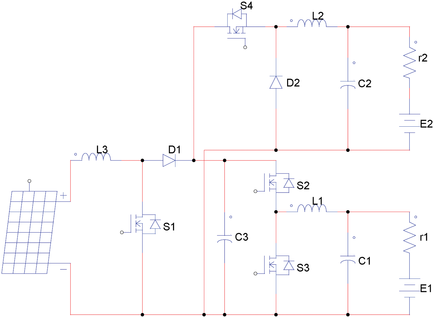
Figure 3: The system converters circuit diagram
The storage battery converter dynamic model in the state-space form is described as follows.
First, the buck operation is represented as:
where il, and vc are the inductor current and the capacitor voltage, respectively. u is a logic number {0:1} that implements the operation of S2 action. C1 and L1 are the filter capacitance and inductance, respectively. Vdc is the DC bus voltage. The matrices A, B, and C are defined respectively as:
Manipulating the previous equations gives:
where ‘
Second, the boost operation is represented as follows. S3 is alternated between ‘on’ and ‘off’ state for periods TonB1 and ToffB1 respectively while S2 is kept in the “off” state. During the ‘on’ period of the boost mode.
where u1 is a logic number {0:1} that implements the operation of S3 action.
To achieve a certain ripple factor “
“R” is the output resistance of the converter, and it can be calculated as:
The value of the converter inductor
To achieve the same ripple factor “
The same procedures are applied to the one-quadrant converter of the EV battery to determine the parameters
The relation of the capacitor
The inductance of the boost converter on the PV side (L3) is chosen according to the following equation:
The proposed control system is divided into three controllers, shown in Fig. 4. The first controller is the MPPT controller. This controller is adapted to absorb maximum power from the PV array. It generates the required boost converter duty cycle that forces the PV into the MPPT conditions. The second controller is the EV converter controller. This controller regulates the EV charging process. The third controller is the battery storage, converter controller. This controller adopts the DC link voltage and the storage battery current.
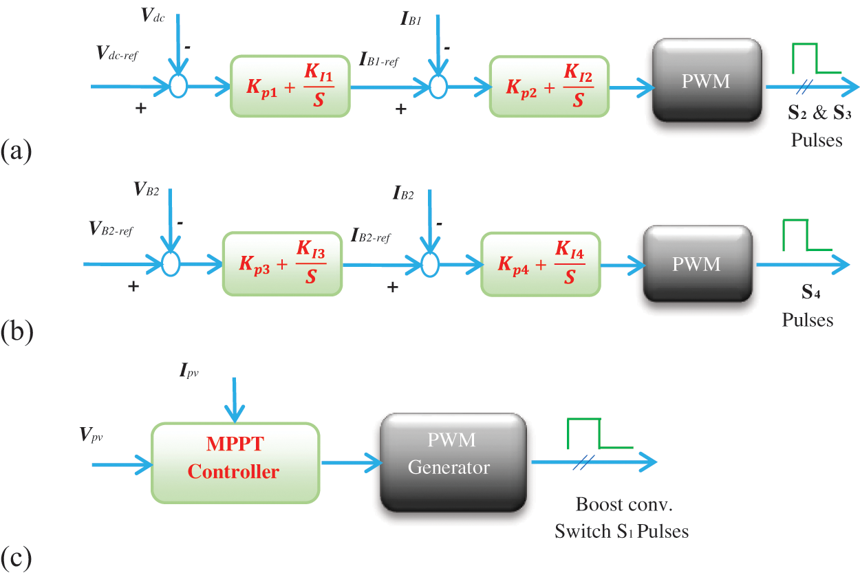
Figure 4: System controllers, (a) voltage and current controller of storage battery B1, (b) Voltage and current controller of EV battery B2, (c) PV maximum power point tracker
The energy utilization of the PV can be improved using the MPPT controller. Nevertheless, the MPPT has been applied using many algorithms [26–29]. The common technique called “Perturb and Observe” is utilized here. The algorithm of this technique is briefly described as follows:
Step 1: Read the present values of PV voltage Vpv-new and current Ipv-new then calculate the present PV power Ppv-new
Step 2: Calculate the increment values of PV power ΔPpv and PV voltage ΔVpv.
Step 3: Update the duty cycle of the switch S1 and generate the corresponding control signal.
Step 4: Go to Step 1 to repeat the cycle of MPPT control.
4.2 The Charge Controller of the EV Converter
The function of this controller is to control the EV charging-process. The common control methods for the charging process are the constant current, constant voltage, and constant voltage/constant current. The last method is usually selected due to its low charging time high current protection. The constant voltage/constant current method is used in the proposed charging station. The controller possesses two nested loops for the current and voltage as shown in Fig. 4b. A simple PI controller is assigned for both loops. The PI controller gains parameters are tuned by Ziegler–Nichols technique.
4.3 The Charge Controller of the ESS Converter
This controller is used to regulate the voltage of the DC-link and control the charge/discharge processes of the ESS battery. The utilized controller this converter is the conventional PI controller. If the PV energy is sufficient to charge the EV, the excess PV energy is sent to charge the ESS batteries. When the ESS batteries are fully charged, the ESS charging ends and the MPPT stop.
The proposed system shown in Fig. 1 is simulated using Matlab/Simulink platform. The simulation process is carried out for the following two cases:
5.1 Case (1): (3 kW) Power System
A relatively high-power system is simulated to verify the effectiveness of the proposed system. Four units of PV panels (125 W) are connected in series to get one PV string. Six strings are connected in parallel to get the PV array of 24 PV panels having a total maximum power of 3 kW. The storage battery bank is four, 12 V, 250 Ah lead-acid batteries connected in series. The lithium-ion battery representing the electric vehicle is a 48 V, 200 Ah. Sun irradiance is assigned three steps. The first period (0 to 5 sec) is 1000 W/m2 corresponding to the maximum power of the PV array. The second (5 to 10 sec) and third (10 to 15 sec) are 700 W/m2 and zero W/m2 corresponding to 70% Pmax and evening time, respectively. The DC bus voltage is set at 100 V. The behavior of the lithium-ion battery is shown in Fig. 5. The S.O.C. is initially set at a low value of 30%. Therefore, the voltage controller generates a high reference charging current of 30 A. The current controller follows the reference current during the three periods and the battery is charged from the PV array from t = 0 to t = 10 s and is charged at the same voltage and current levels during the third period from t = 10 s to t = 15 s through the lead-acid storage battery bank.
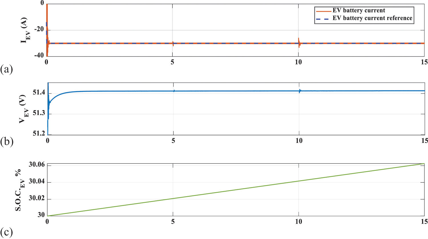
Figure 5: Lithium-ion battery (B2) performance, (a) battery current (A), (b) battery voltage (V), (c) state of charge (%)
Fig. 6 presents the performance of the PV array and storage battery. The MPPT algorithm always tracks the maximum power during the first two periods while all PV array values are zero during the evening period. The performance of the lead-acid storage battery bank (B1) is presented in Figs. 6f–6h. During the first period with maximum PV array power, the lead-acid storage battery bank is charged rapidly with a high charging current and high state of charge (S.O.C) rate. During the second period, the rate of charging is reduced due to the reduction in solar irradiance.
After sunset, the PV array is disconnected. The battery current becomes positive, and the battery starts discharging. The battery voltage and S.O.C. starts decreasing. Fig. 6e gives the DC bus voltage and its reference. The voltage controller of the storage battery generates the required charging current of the storage battery during the first two periods and the required discharging current during the third period so that the DC bus voltage is always kept constant.
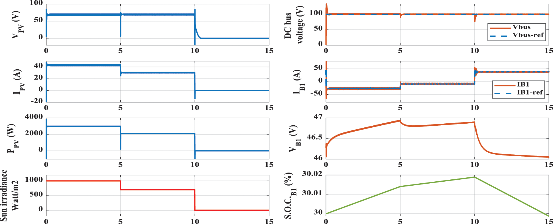
Figure 6: Case 1 performance, (a) PV array voltage, (b) PV array current, (c) PV array power, (d) irradiance (W/m2), (e) DC bus voltage and its reference, (f) storage battery current and its reference, (g) storage battery voltage and (h) storage battery state of charge
5.2 Case (2): (120 W) Power System
The system power and parameters are typically the same as the implemented experimental setup. In this case, both the simulation and experimental setup specifications are:
• PV panel (copex model: P120) specifications:
Peak power Pmax 120 W, Voltage at maximum power Vmp 16 V, current at maximum power Imp 7.5 A, open-circuit voltage Voc 19.2 V, and short-circuit current Is.c. 8.82 A.
• Storage battery (Lead Acid) specifications:
Rating: 65 Ah, nominal voltage: 12 V, fully charged voltage: 13 V, cut-off voltage: 9 V, maximum charging current: 0.2 C = 13 A and maximum discharging current: 0.2 C = 13 A.
• Battery representing EV (Lithium-ion):
Construction: four batteries connected in series, rating: 6.5 Ah, nominal voltage: 3.7 V per battery, fully charged voltage: 4.25 V per battery, cut-off voltage: 3 V per battery, maximum charging current = 3 A and maximum discharging current = 5 A. Four series-connected Li-ion batteries form a battery pack having a rating 6.5 Ah, it has 14.8 V rated voltage, the fully charged/cut-off voltage is 17 V/12 V respectively. The parameters of the converters for low power case are listed in Tab. 1. Figs. 7 and 8 present the responses of the system against to step variations in the PV insolation level. The variations of the PV irradiation are shown in Fig. 7a. The response of the voltage of the DC bus precisely follows its reference (25 V), as presented in Fig. 7b. The S.O.C. of the lead-acid battery B2 is shown in Fig. 7c.
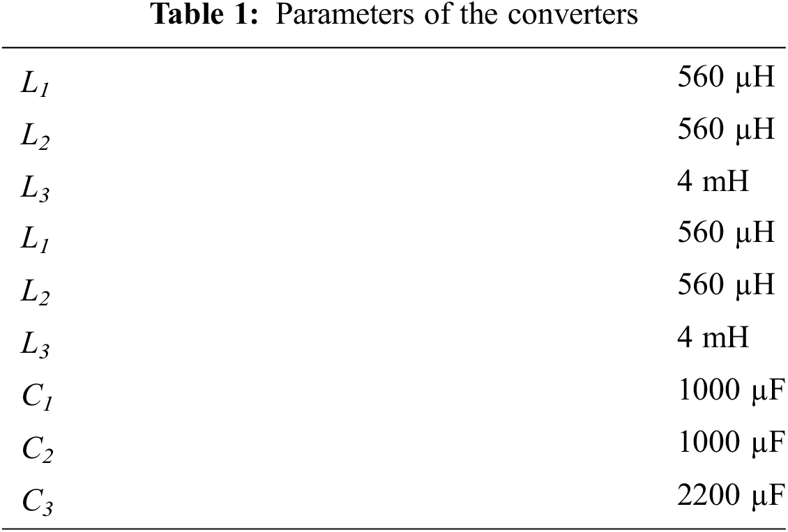
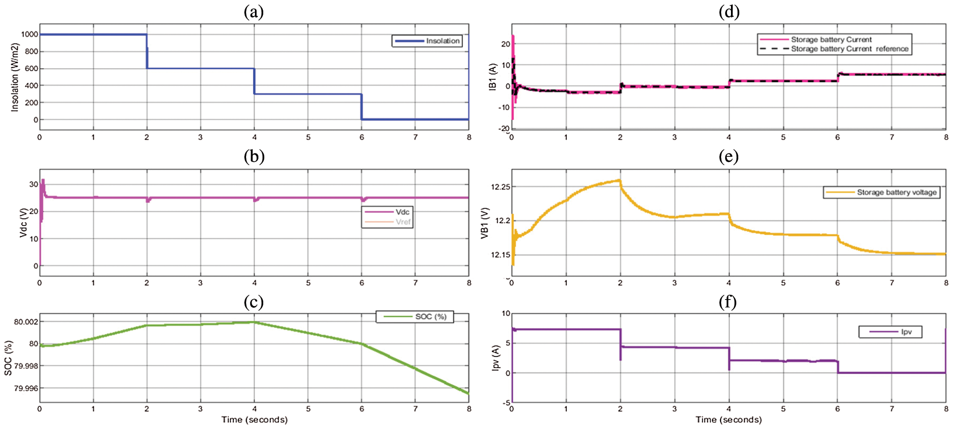
Figure 7: (a) PV irradiation level, (b) DC bus voltage, (c) the lead-acid battery (B1) state of charge, (d) the current of the battery B1, (e) the voltage of the battery B1 (f) the current of the PV
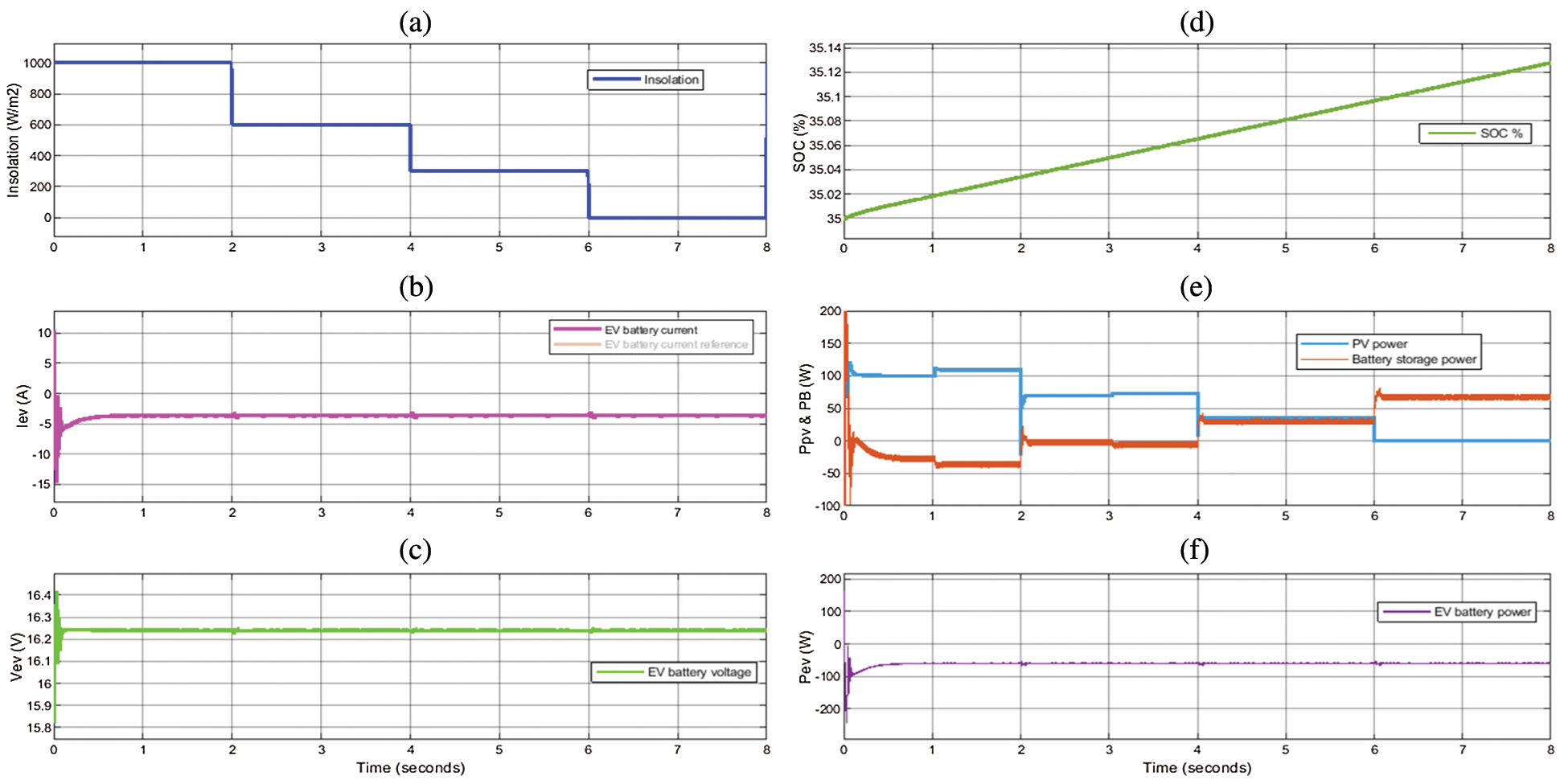
Figure 8: (a) PV irradiation level, (b) the EV battery (B2) current, (c) EV battery voltage, (d) the EV battery state of charge, (e) the power of the PV and B2 battery (f) the power of the EV
When the irradiation is greater than (60%), the PV generates enough energy to charge the EV and serve the rest in the ESS battery. This occurs at the first 4 seconds. If the irradiation is less than (60%), the generated PV energy is not sufficient to charge the EV. Therefore, the ESS battery starts discharging to account for the PV energy drop. It is seen from Fig. 7d that the ESS-battery current follows well its reference. Also, the charging and discharging processes track and compensate for the irradiation level. Fig. 7e shows the voltage of B1 battery where it increases with charging and decreases with discharging. The PV current is shown in Fig. 7f. The current level is the same as the MPPT conditions. The variations of the PV irradiation are shown in Fig. 8a. The charging current of the EV follows perfectly its reference value as shown in Fig. 8b. Fig. 8c shows the voltage of the B2 battery which is continuously charged as its S.O.C. can be illustrated in Fig. 8d. Figs. 8e and 8f present the PV power, the EV battery power, and the power of the B1 battery. When the irradiation is greater than (60%), the PV generates enough energy to charge the EV and serve the rest in the ESS battery. This occurs at the first 4 seconds. If the irradiation is less than (60%), the generated PV energy is not sufficient to charge the EV. It is noted that the EV charging is kept constant against all disturbances, as presented in Fig. 8f.
6 Design Guides for Different Power Levels
This section presents design guides for selecting the parameters of the converters assuming that the calculated parameters which are given in Tab. 1 are the base values based on
The following assumptions are considered:
-
-
- The storage battery voltage level
- The EV battery voltage level
The power level of the charging station
As the inductor current ripple is usually a percentage value of the average inductor current, then
Therefore Eqs. (3), (7), (9), (10), (12), (15), (16) and (18) are replaced in the higher power charging station by Eqs. (21)–(28) respectively noting that
“R” is the output resistance of the converter and it can be calculated as:
These design equations help for proper selection for inductances and capacitances of the converter keeping into consideration the maximum currents of inductors and maximum voltages of capacitors in high power applications.
An experimental prototype is built to verify the simulation results of the proposed system. The prototype has the same specifications as indicated in case 2. The practical system has the following converters:
• DC-DC boost converter with MPPT on the PV panel side
• A bidirectional boost-buck converter on the storage lead-acid battery (B1) side.
• A buck converter on the lithium-ion battery (B2) side.
A single-chip PIC18F4550 microcontroller is utilized to achieve the operation of the controllers simultaneously. The microcontroller crystal oscillator frequency is set at 16 MHz. The microcontroller receives the signals of Ipv, Vpv, IB1, VB1 Vdc, IB2 and VB2. Then the microcontroller utilizes its modules Timer0, Timer1, Timer2 and CCP to perform the controllers of the system. The outputs of the microcontroller are the signals of switches S1, S2, S3 and S4. The five controllers are:
• DC-DC boost converter controller
The microcontroller receives the PV voltage and current, performs the perturb and observe MPPT algorithm, then generates the control signal to S1.
• DC bus voltage controller
This controller regulates the DC-bus voltage to track a certain constant value. The stability of the system is directly related to the regulation grade of this controller. The output of this controller is the reference current of B2.
• Lead-acid battery current controller
This controller utilizes the reference battery current and generates the control signal to either switch S2 (charging) or to switch S3 (discharging).
• Lithium-ion voltage controller and current controller
The lithium-ion battery is charged using constant voltage/current method. The outer loop is set for the voltage controller that regulates the battery voltage and produces the reference current for the inner loop. The inner loop (current controller) generates the control signal to S4.
The experimental platform has been implemented in the laboratory to verify the feasibility of the proposed system as shown in Fig. 9. The current controller of the lithium-ion battery is tested at different current levels (3A, 2A, and 1A) as illustrated in Fig. 10. The voltage controller forces the battery voltage to change according to each current value. Fig. 11 shows the effects of disconnecting the PV panel. After disconnecting the PV array, the DC link voltage is kept constant by the controller. However, the lead-acid battery discharges and its voltage drops. The controller of the buck converter of the lithium-ion battery keeps its voltage level and current at the same values before disconnecting the PV panel.
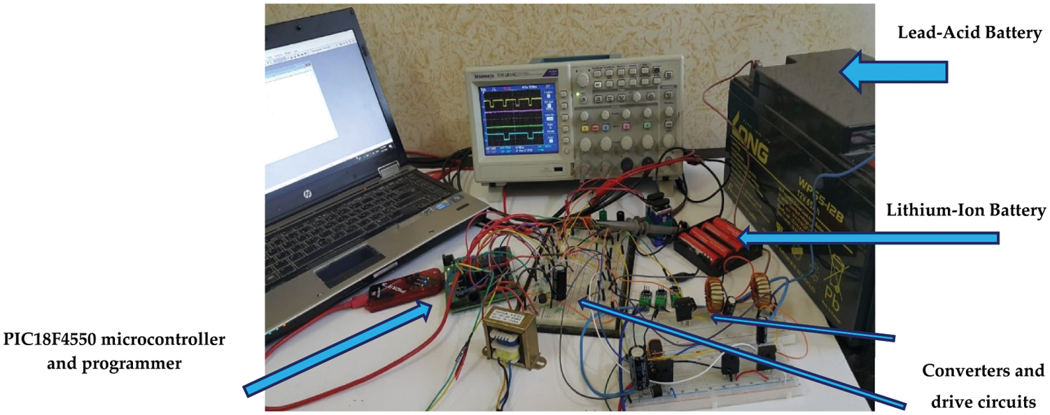
Figure 9: Physical experimental setup
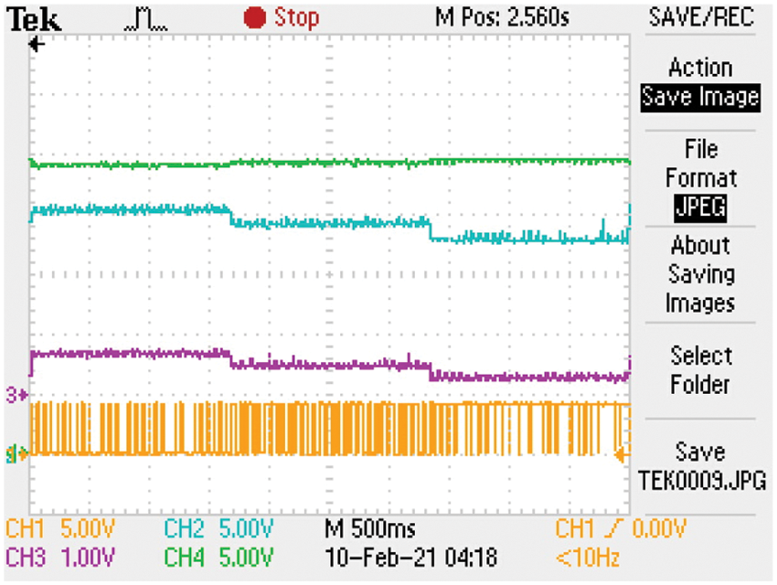
Figure 10: Ch1: Control signal of buck-converter switch for Li-ion (5 V/div.) Ch2: the voltage of B1 (5 V/div.) Ch3: the current of B1 (4 A/div), Ch4: the DC link voltage (5 V/div)
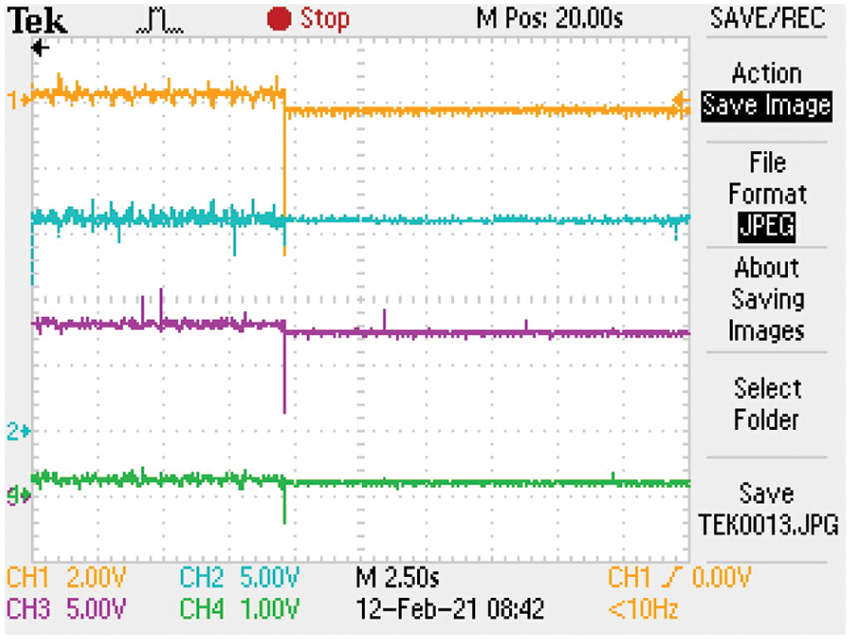
Figure 11: Ch1: The B2 current (6 A/div.) Ch2: The B1 voltage (5 V/div.) Ch3: The B2 voltage (5 V/div.), Ch4: The B1 current (4 A/div.). First: Connected PV panel, second: Disconnected PV panel
Disconnecting and reconnecting the PV panel are illustrated in Figs. 12a and 12b. In Fig. 12a, if the PV array is removed, the battery B2 charges the EV battery B1. The B1 voltage and the DC-link voltage are kept at the set values. However, the lead-acid battery voltage decreases. Fig. 12b shows the reconnection of the PV panel. Both batteries are being charged, and the lead-acid battery voltage increases. Figs. 13a and 13b show the control pulses of the converter switches in connecting and disconnecting the PV array. The previous results are considered as short-time results where they can be monitored by oscilloscope. The long-time results are that associated with the charging process. The software in the laboratory from (Lab-Volt) can store the results at minimum intervals of one second. Fig. 14a presents part of the charging process of EV battery while Fig. 14b gives the performance of the MPPT with a step change in the load at t = 70 s.
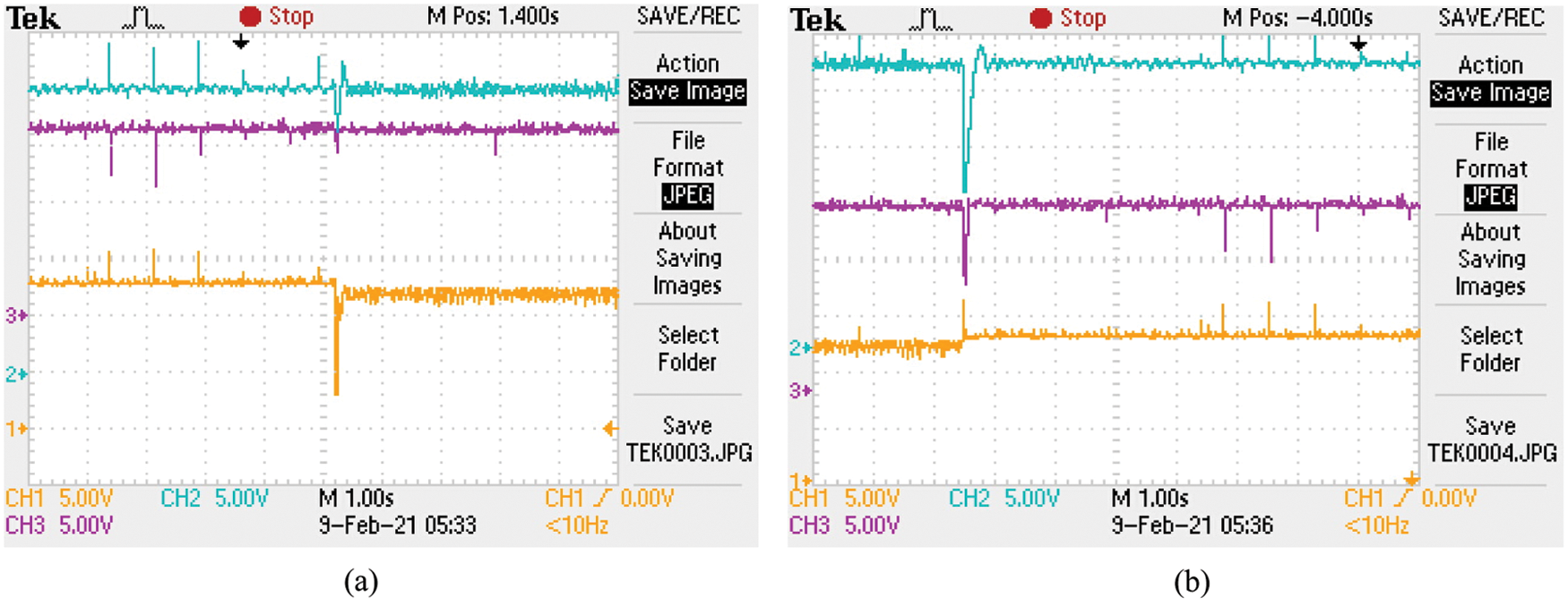
Figure 12: PV panel, (a) disconnecting, (b) reconnecting. Ch1: Lead Acid battery voltage (5 V/div.) Ch2: DC-link voltage (5 V/div.), Ch3: Li-ion battery voltage (5 V/div)
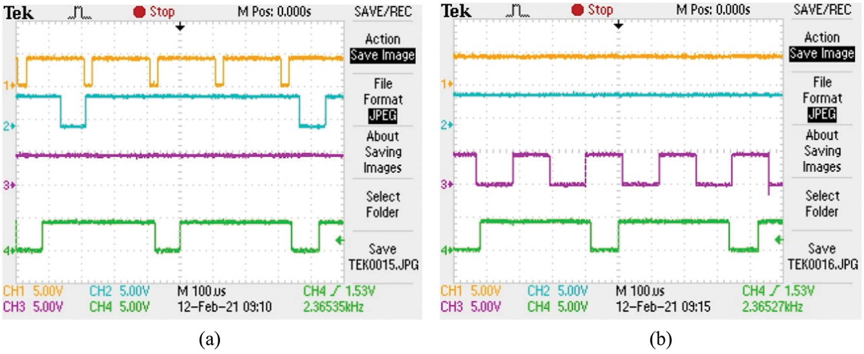
Figure 13: The microcontroller control pulses for the converter switches, (a) The PV array is connected, (b) PV panel is disconnected. S1 (CH1), S2 (CH2), S3 (CH3), S4 (CH4)
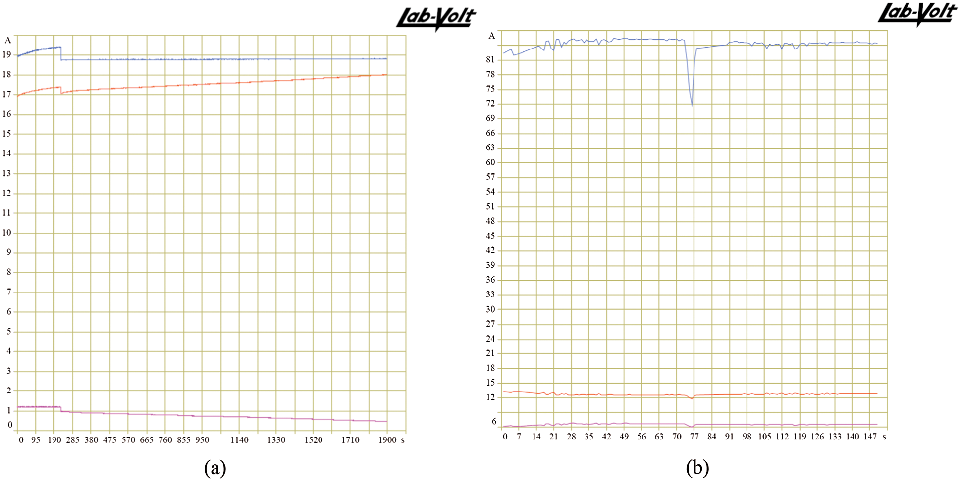
Figure 14: (a) Case 2: Voltage and current of lithium-ion battery during the charging process (Red: battery voltage, Violet: battery current) – Voltage applied to the battery (blue) (b) MPPT performance: from top to bottom; PV power, voltage, and current
An efficient EV charging station based on a PV energy source has been proposed. Analysis and simulation of the system were presented including two cases: low power (120 W) and high power (3 kW) charging system. The PI voltage and current controllers were employed to control the charging and discharging of a lead-acid battery pack that represents the energy storage system. Another voltage and current controller were utilized to adjust the charging of an EV battery (lithium-ion battery). The power of the PV panel was always maximized to meet the required energy of the EV battery and store the excessive energy in the lead-acid battery. Simulation results in both cases of study and experimental results were very close and verify the effectiveness of the proposed system.
A single-chip PIC18F4550 microcontroller is utilized to realize the operation of controllers and generate the control signals of the power switches thus lowering the hardware implementation complexity and cost. The system was tested successfully for 120 W and 3 kW power levels, and it could be extended for higher power charging stations where the proposed design guides can successfully help for selecting the suitable parameters of the converters. Also, it could be applied in urban and remote areas as well.
Funding Statement: This research was funded by the Deanship of Scientific Research, Taif University, KSA (Research project number 1-441-99).
Conflicts of Interest: The authors declare that they have no conflicts of interest to report regarding the present study.
1. R. Carter, A. Cruden, P. J. Hall and A. S. Zaher, “An improved lead-acid battery pack model for use in power simulations of electric vehicles,” IEEE Transactions in Energy Conversion, vol. 27, no. 1, pp. 21–28, 2012. [Google Scholar]
2. I. O. Lee, “Hybrid PWM-resonant converter for electric vehicle on-board battery chargers,” IEEE Transactions on Power Electronics, vol. 31, no. 5, pp. 3639–3649, 2016. [Google Scholar]
3. A. Kuperman, U. Levy, J. Goren, A. Zafransky and A. Savernin, “Battery charger for electric vehicle traction battery switch station,” IEEE Transactions on Industrial Electronics, vol. 60, no. 12, pp. 5391–5399, 2013. [Google Scholar]
4. H. J. Chiu, L. W. Lin, P. L. Pan and M. H. Tseng, “A novel rapid charger for lead-acid batteries with energy recovery,” IEEE Transactions on Power Electronics, vol. 21, no. 3, pp. 640–647, 2006. [Google Scholar]
5. Y. H. Jung, J. H. Jung, H. E. Jeong, J. H. Jung, J. S. An et al., “A fast and highly accurate battery charger with accurate built-in resistance detection,” IEEE Transactions on Power Electronics, vol. 33, no. 12, pp. 10051–10054, 2018. [Google Scholar]
6. S. Haghbin, S. Lundmark, M. Alaküla and O. Carlson, “Grid-connected integrated battery chargers in vehicle applications: Review and new solution,” IEEE Transactions on Industrial Electronics, vol. 60, no. 2, pp. 459–473, 2013. [Google Scholar]
7. N. Tashakor, E. Farjah and T. Ghanbari, “A bidirectional battery charger with modular integrated charge equalization circuit,” IEEE Transactions on Power Electronics, vol. 32, no. 3, pp. 2133–2145, 2017. [Google Scholar]
8. H. N. de Melo, J. Pedro, F. Trovao, P. G. Pereirinha, H. M. Jorge et al., “A controllable bidirectional battery charger for electric vehicles with vehicle-to-grid capability,” IEEE Transactions on Vehicular Technology, vol. 67, no. 1, pp. 114–123, 2018. [Google Scholar]
9. M. A. H. Rafi and J. Bauman, “A comprehensive review of DC fast charging stations with energy storage: Architectures, power converters, and analysis,” IEEE Transactions on Transportation Electrification, vol. 7, no. 2, pp. 345–368, 2021. [Google Scholar]
10. M. Yilmaz and P. T. Krein, “Review of battery charger topologies, charging power levels, and infrastructure for plug-in electric and hybrid vehicles,” IEEE Transactions on Power Electronics, vol. 28, no. 5, pp. 2151–2169, 2013. [Google Scholar]
11. Z. Amjadi and S. S. Williamson, “Power- electronic-based solutions for plug-in hybrid electric vehicle energy storage and management systems,” IEEE Transactions on Industrial Electronics, vol. 57, no. 2, pp. 608–616, 2010. [Google Scholar]
12. A. B. de Mozos, G. R. C. Mouli and P. Bauer, “Evaluation of topologies for a solar powered bidirectional electric vehicle charger,” IET Power Electronics, vol. 12, no. 14, pp. 3675–3687, 2019. [Google Scholar]
13. V. Kumar, V. R. Teja, M. Singh and S. Mishra, “PV based off-grid charging station for electric vehicle,” International Federation of Automatic Control, vol. 52, no. 4, pp. 276–281, 2019. [Google Scholar]
14. G. R. Chandra Mouli, J. Schijffelen, M. van den Heuvel, M. Kardolus and P. Bauer, “A 10 kW solar-powered bidirectional EV charger compatible with CHAdeMO and COMBO,” IEEE Transactions on Power Electronics, vol. 34, no. 2, pp. 1082–1098, 2019. [Google Scholar]
15. V. Monteiro, J. G. Pinto and J. L. Afonso, “Experimental validation of a three-port integrated topology to interface electric vehicles and renewables with the electrical grid,” IEEE Transactions on Industrial Informatics, vol. 14, no. 6, pp. 2364–2374, 2018. [Google Scholar]
16. S. A. Singh, G. Carli, N. A. Azeez and S. S. Williamson, “Modeling, design, control, and implementation of a modified z-source integrated PV/Grid/EV DC Charger/Inverter,” IEEE Transactions on Industrial Electronics, vol. 65, no. 6, pp. 5213–5220, 2018. [Google Scholar]
17. K. Chaudhari, A. Ukil, K. N. Kumar, U. Manandhar and S. K. Kollimalla, “Hybrid optimization for economic deployment of ESS in PV-integrated EV charging stations,” IEEE Transactions on Industrial Informatics, vol. 14, no. 1, pp. 106–116, 2018. [Google Scholar]
18. Y. Zhang, P. You and L. Cai, “Optimal charging scheduling by pricing for EV charging station with dual charging modes,” IEEE Transactions on Intelligent Transportation Systems, vol. 20, no. 9, pp. 3386–3396, 2019. [Google Scholar]
19. J. C. Hernandez and F. S. Sutil, “Electric vehicle charging stations fed by renewable: PV and train regenerative braking,” IEEE Latin America Transactions, vol. 14, no. 7, pp. 3262–3269, 2016. [Google Scholar]
20. R. Mkahl, A. N. S. Moh and M. Wack, “Modeling and simulation of standalone photovoltaic charging stations for electric vehicles,” International Scholar Scientific Research Innovation, vol. 9, no. 1, pp. 72–80, 2015. [Google Scholar]
21. K. Kouka and L. Krichen, “Energy management strategy of a photovoltaic electric vehicle charging station,” in Proc. of 19th Int. Conf. Science Technology Automation Control Computer Engineering, Sousse, Tunisia, pp. 124–129, 2019. [Google Scholar]
22. T. S. Biya and M. R. Sindhu, “Design and power management of solar powered electric vehicle charging station with energy storage system,” in Proc. of 3rd Int. Conf. of Electronics Communication Aerospace Technology, ICECA, India, pp. 815–820, 2019. [Google Scholar]
23. S. A. Zaid and A. M. Kassem, “Review, analysis and improving the utilization factor of a PV-grid connected system via HERIC transformerless approach,” Renewable and Sustainable Energy Reviews, vol. 73, no. 3, pp. 1061–1069, 2017. [Google Scholar]
24. Y. Atia, “Photovoltaic maximum power point tracking using SEPIC converter,” Shebin El-Kom Journal, vol. 36, no. 4, pp. 33–40, 2009. [Google Scholar]
25. M. Rashid, “Power Electronics Handbook,” 2nd ed., Elsevier Press, 2011. [Google Scholar]
26. H. Elbalawi and S. A. Zaid, “An H5 Transformerless inverter for grid connected PV system with improved utilization factor and simple maximum power point algorithm,” Energies, vol. 11, no. 11, 2912, 2018. [Google Scholar]
27. M. A. Husain, A. Tariq, S. Hameed, M. S. B. Arif and A. Jain, “Comparative assessment of maximum power point tracking procedures for photovoltaic systems,” Green Energy Environment, vol. 2, pp. 5–17, 2017. [Google Scholar]
28. P. Das, “Maximum power tracking based open-circuit voltage method for PV system,” Energy Procedia, vol. 90, pp. 2–13, 2016. [Google Scholar]
29. H. Albalawi and S. A. Zaid, “Performance improvement of a grid-tied neutral-point-clamped 3-φ transformerless inverter using model predictive control,” Processes, vol. 7, no. 11, 856, 2019. [Google Scholar]
 | This work is licensed under a Creative Commons Attribution 4.0 International License, which permits unrestricted use, distribution, and reproduction in any medium, provided the original work is properly cited. |