DOI:10.32604/csse.2022.024979
| Computer Systems Science & Engineering DOI:10.32604/csse.2022.024979 | |
| Article |
Low-Cost IMU Sensors for Satellite Maturity Improvement
Department of Science and Technology, College of Ranyah, Taif University, P.O. Box 11099, Taif, 21944, Saudi Arabia
*Corresponding Author: Omar Ben Bahri. Email: obinbahri@tu.edu.sa
Received: 06 November 2021; Accepted: 20 December 2021
Abstract: The satellite technology proves its impact in the modern era with its wide benefits and applications. However, the cost of the development in this field presents gaps in many countries, almost the developed countries. Therefore, this paper provides a rich platform around low-cost sensors in order to improve maturity in space technology, mostly the system of attitude determination and control. The development of this knowledge turns out to be very interesting in order to achieve a space mission which leads to the progression of the spatial technology readiness level (TRL) defined by the international measurement scale which is able to estimate the technological maturity. Thus, the idea is carried out for the development of low-cost sensors’ system for attitude determination around an Arduino board. A sensor fusion method was applied on three types of sensors: accelerometer, magnetometer, and gyroscope in order to detect the reliable orientation. It is aimed to apply quaternion based Kalman filter on different platform than previous systems. It is succeeded therefore to improve measurement accuracy around low-cost sensor to achieve the main goal of this paper.
Keywords: ADS; IMU sensors; kalman filter; low-cost; satellite
The space exploitation is beneficial in several areas, such as climate and meteorological monitoring, access to health care and education, water management, transport efficiency and agriculture, peacekeeping, security, and humanitarian aid. The list of space applications affecting life on earth is virtually endless, and many more contributions are currently either under development or being researched. Indeed, space technology has gradually revealed itself. The question we must ask ourselves is to what extent the knowledge accumulated experience in the process of producing this technology can serve the progress of developing countries, especially, as an example of the propagation form.
Space is a very difficult environment, which makes launching a satellite into orbit is a very complicated task and needs several requirements, such as, in-depth knowledge of the phases, the objectives and constraints of space missions which leads to meet all the criteria for a requested space application. All space missions are made up of main phases. The arrangement of these phases forms the overall structure of a space mission to define NASA’s space engineering system [1].
This motivated the birth of small satellites such as nano and pico-satellites to provide an affordable means for the development of low-cost space missions. This led the rapid increase in emerging technologies for space education [2]. Small satellites present interest practical tools for academies and universities around the world [3–5]. The dissemination and mastery of “CanSat” type pico-satellites have led to open a new branch in space education programs [6]. In fact, the main objective of the CanSat project is to offer a didactic demonstration to space engineering.
It opens the field to benefit practical application around complex system type pico and nano satellites by introducing the design, the construction and launching phases. In addition, in several universities around the world, CanSat projects are being launched to provide the opportunity to reduce the costs of space access [7–9]. Multiple objectives occur when speaking about a space mission. It requires an in-depth concept study on the same criteria of a conventional space mission in order to launch a CanSat. Taking the example of the “Tokyo Institute of Technology”, besides the didactic objective of the mission, they launched five CanSats which include cameras, GPS receivers and communication systems, to accomplish three objectives; provide demonstration of space imagery, attitude determination and satellite-to-command station telecommunication [10].
Until now, the use of pico-satellites has been confined for educational purposes that have been succeeded to provide a fruitful practical experience in space engineering for academics and universities. It has included multidisciplinary fields. In addition, it is succeeded to improve knowledge about space engineering in universities, including those in developing countries. With innovation and investment in research into these devices, it can be proven their efficiencies to be a powerful tool for professional experiments, if combined with scientific devices.
Besides the didactic role of the mission proposed consequently, we embarked on a didactic mission to affordably experiment and fill the gaps in the basics for a satellite attitude determination system (ADS), while it is among the pivotal satellite systems. Therefore, the idea resides on the development of an attitude determination system based on low-cost sensors around and Arduino board and inertial measuring unit (IMU) sensors. It tackles maturity improvement about this system with providing a test platform for a quaternion based Kalman filter (KF) in order to detect the reliable orientation.
In fact, IMU systems are widely used in terms of Indoor Positioning Systems (IPS) [11], stabilized platform application [12], monitoring [13], and so on. Thus, IMU system can offer a great platform to develop an ADS for space operation demonstration. Indeed, the estimation of attitude is based generally on the use of the inertial sensors determined by three methods; Using gyroscopes [14], combining the data of accelerometer and gyroscope [15], or apply the sensor fusion method on the three types of sensors [16]. However, orientation detection suffers accurate measurements relying on one sensor alone among these three types. According to this brief analysis about these different sensors, it is necessary to fusion measurements of the three types of sensors, in order to benefit their reliability provided by the integration of all sensors. The method proposed, therefore, for the attitude estimation, is based on gyroscope, magnetometer, and accelerometer measurements.
Therefore, and based on these experiences we aim to develop a prototype demonstration around Arduino, IMU and a virtual instrument platform as an ADS for satellite operation demonstration. A method of measurement improvement was developed around a quaternion based Kalman filter in order to detect the correct orientation. The novelty presents in the implementation of low-cost sensors to develop a complete demonstration about satellite ADS, including the improvement methods of accuracy.
This work was performed following the NASA’s engineering architecture system for space missions (Fig. 1) [1].
This project meets the low-cost requirements in order to provide an affordable system to develop the maturity of space technology. In addition, the system is conceived to develop a low-cost ADS system for testing and improving data accuracy for IMU sensors, in order to detect the reliable attitude.
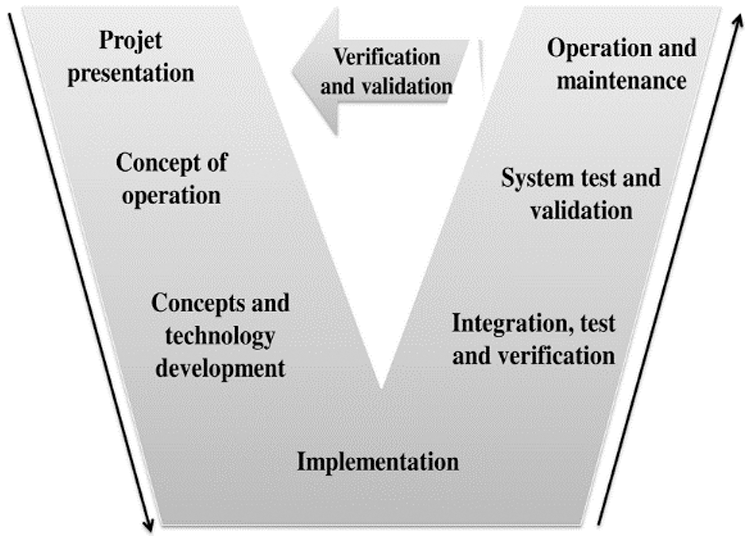
Figure 1: NASA’s space mission architecture [1]
3 Concept of Operation and Technology Development
Multiple objectives appear when we are talking about a space mission. It requires an in-depth concept study on the same criteria of a classic space mission in order to launch an idea around a space mission. This needs a concept of operation as primary step towards a complete mission development. Thus, the system proposed for the ADS is composed on three main parts: IMU sensors, Arduino board and virtual instrument software for data management.
In order to detect the reliable attitude of the system, the sensor fusion method was proposed around the accelerometer, the gyroscope and magnetometer sensors. Therefore, a quaternion based Kalman filter was applied using virtual instrument software, in order to improve the data accuracy (Fig. 2).
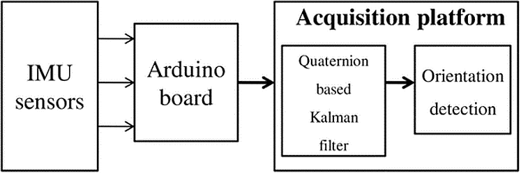
Figure 2: Data acquisition architecture
This figure presents the data flow through the attitude determination components. The Arduino board aimed to act as the On-Board Computer (OBC) of the satellite [17], by acquiring data from IMU sensors in order to be sent to the virtual instrument software. This platform provides an affordable way to develop the accuracy improvement algorithms for sensors measurements. In addition, it provides a complete demonstration about satellite attitude estimation.
In fact, IMU sensors are viral, and it is used for indoor positioning systems [18,19], and attitude determination purposes [20] based on different techniques for data accuracy improvement. In fact, IMU low-cost sensors suffer measurement accuracy which leads to develop techniques for more precision. Therefore, the novelty resides on combining three types of low-cost sensors measurements, and the similar method of satellites, for a reliable attitude determination. In addition, a quaternion based on Kalman filter was applied in order to correct errors.
In space mission, satellite attitude control is one of the most important points of the Attitude and Orbit Control Subsystem (AOCS) for a satellite. Its objective is to maintain the desired attitude (angular orientation) of the satellite because it is important to point at its target so it will have ability to succeed in its mission.
Here, several types of sensors and actuators can be used. Our work particularly focuses on the use of the quaternion based Kalman filter for the global estimation of attitude. The objectives of this work therefore reside on:
• The development of a mathematical model of attitude under the presence of various disturbances.
• The development of reference models for the attitude estimator.
• Simulation of attitude sensors such as the accelerometer, the gyroscope, and the magnetometer.
• The development of an algorithm for the global estimation of the attitude using the quaternion based KF around the sensor fusion technique.
The first step therefore is carried out for the estimation of the sensors’ measurements drift and errors. Thus, many tests were performed with random orientations of the IMU sensors. Indeed, understanding the performance of the sensors is essential before using the sensors in programs. Therefore, this section provides a detailed evaluation on the performance of the used sensors in such as accelerometer, gyroscope and magnetometer.
4.1 Accelerometer Performances Tests
The bias presents the most important error’s source for an accelerometer. It presents the offset of accelerometer output signal from the actual value, in m/s2. It is a constant error of ε which causes a position error that increases with time. The error accumulated in position is:
Fig. 3 illustrates the results of the accelerometer measurements for the three axes X, Y and Z.
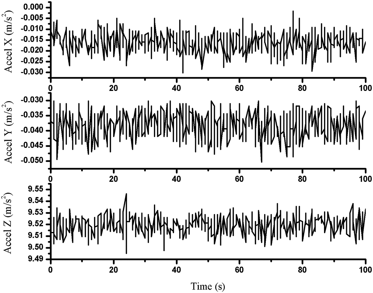
Figure 3: Accelerometer error measurements in three axes X, Y and Z
Tab. 1 shows the results of the statistical analysis on the absolute errors of the test results. It shows that the deviations between the measured values and the standard values included between 0.0036 and 0.0191 m/s2. The total standard deviation for acceleration equals 0.0264 m/s2, which over time could generate a large error.

4.2 Gyroscope Performances Tests
In general, the gyroscope presents an orientation measuring device. It is based on the principles of conservation of angular momentum [21]. Its error generally is the bias which is the average output of the gyroscope when it is not undergoing any rotation (the offset of the output signal from the actual value).
Indeed, the constant bias error of a gyroscope can be estimated by taking a long-term average of its output while no rotation occurred. Therefore, for an accurate measurement, it is trivial to subtracting the bias from the output once the bias is known, [22].
Thus, the test was performed when the IMU device is stable on the table in order to estimate the bias. Fig. 4 shows the gyroscope measurements in three axes when the device is stationary.
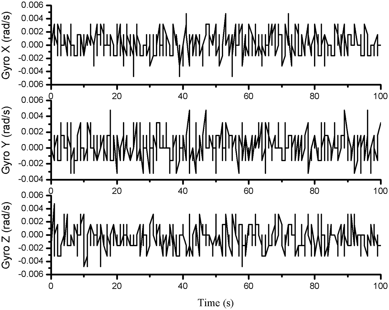
Figure 4: Gyroscope error measurements in three axes X, Y and Z
Tab. 2 shows the results of the statistical analysis on the absolute errors of the gyroscope test results. It shows that the deviations between the measured values and the standard values included between 0.00096 and 0.00095 rad/s. The total standard deviation for the gyroscope is 0.00279 rad/s, which over time could generate a large error.

4.3 Magnetometer Performances Tests
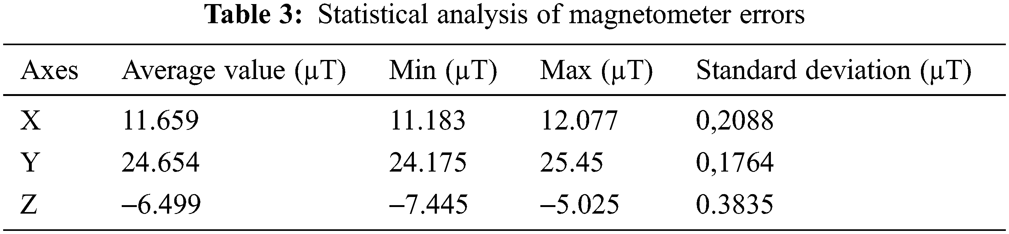
The magnetometer measures the strength of the ambient magnetic field in micro-Tesla (μT), in the x, y and z axes. Fig. 5 shows the magnetic field measurements in the x, y and z axes respectively.
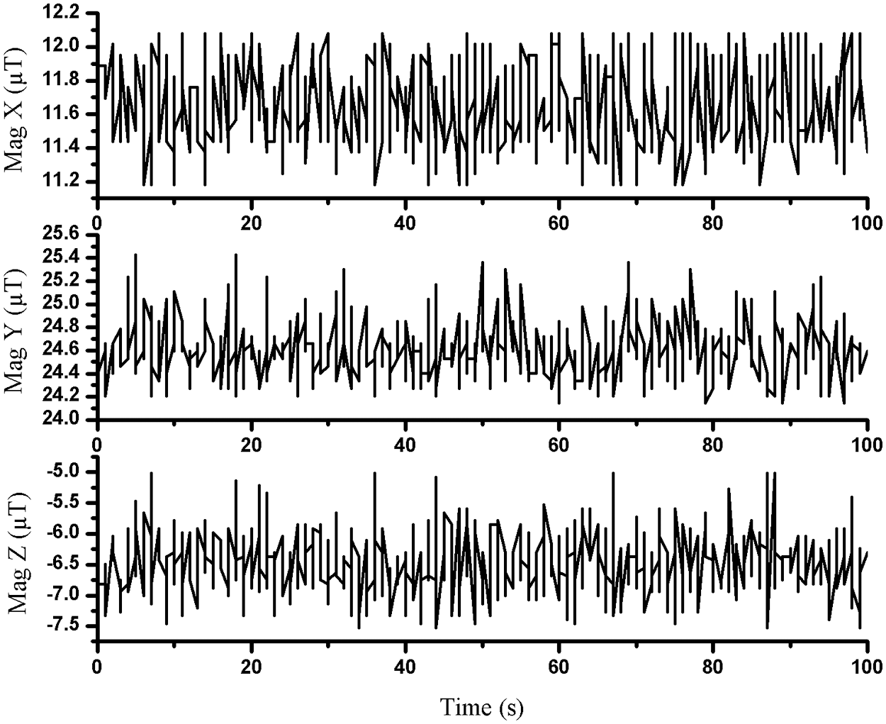
Figure 5: Magnetometer error measurements in three axes X, Y and Z
The test statistics are displayed in the Tab. 3. An interesting observation is the sensitivity of the sensor, which results in a rather high standard deviation of more than 0.17 µT for each axis, for a sum of 0.7687 µT which presents a significant error with time.
5 System Integration and Validation
As mentioned, the attitude determination system plays as a pivotal system in satellite application. It is necessary to estimate the reliable attitude in order to maintain the projection on the desired coverage area. Thus, the errors estimations of the sensors’ measurements lead to develop the adequate algorithm for data accuracy improvement. The method therefore is based on applied a filtering system around a quaternion based KF.
Indeed, the sensor fusion method was applied in order to combine measurements of the three sensors used. This method improves the weakness of accuracy when using one sensor alone to detect the device orientation. The quaternion therefore was applied as it is suffering less from the problems of singularity present on some rotation representation such as the method of rotation matrix or Euler angles.
The quaternion representation of a rotation can be interpreted as an axis angle representation of the rotation based on the quaternion vector:
The quaternion seems the adequate representation to yield the reliable orientation that provides the simplest method which used a minimal number of parameters [23].
Indeed, the objective of this work is to provide the reliable orientation based on alternative filtering and estimation techniques. The previous developed techniques are adequate for static or quasi-static movements. Therefore, we will be mainly interested in improving the orientation estimation of in case of dynamic movements. We proposed therefore, as preliminary step, to calculate quaternion of measurement using 3-axis accelerometer and 3-axis magnetometer. While the second step was carried out to add gyroscopes’ measurements to correct noises related to quaternion.
There is a mathematical relation allowing to express the angles of Euler as a function of the elements of the quaternion as defined by the equations below.
This transformation is the most used since it has no singularity, unlike the DCM rotation matrix. In addition, working with a minimum of parameters allows to reduce the calculation process. Finally, and most importantly, the use of quaternions increases the accuracy of the attitude. Thus, it allows to pass between these and the Euler angles without singularity.
Although the calculated quaternion is noisy especially during dynamic phases of movement, it serves to correct the attitude estimated by the gyro measurements. This step often generates a higher computation time. Thus, we propose to apply a filtering technique that directly uses the measurements from the accelerometer, the magnetometer and the gyrometric bias. Considering therefore that the gyroscope measurements are marred by noise, Eq. (6) [24].
where b is the gyroscope’s bias vector.
In order to merge this angular speed measurement with the rest of the measurements, we consider applying the sensor fusion technique as presented in the above system.
where [q0 q1 q2 q3]T represent the estimated states, expressed by the quaternion of rotation.
Therefore, as the Unscented Kalman Filter (UKF) has the advantage of calculating an approximate solution to the problem of optimal nonlinear estimation of the state of a dynamic system [25,26], a modified UKF was applied to yield the reliable orientation estimation. The UKF makes it possible to calculate the approximations of the estimation problem in the case where:
where xk is the state at time k, uk is the input measured,
Applying the nonlinear transformations such as:
UKF is mainly based on the sigma point approach (SPA) technique, which is usually used to determine the approximation of the Gaussian random process xk|k, over time, to which nonlinear transformations are applied which capture the true covariance
When the dynamics of the observed system have invariance properties, the basic equations do not allow us to synthesize an estimator of the state of the system with similar properties. However, from the point of view of convergence, it can be very interesting to seek to give any candidate filter estimator the invariance properties of the system. Indeed, the linear error terms
Indeed, the redefinition of the notion of covariance matrix, associating it with invariant estimation errors, modifies:
• The calculation of the predicted covariance relating to the output y such that:
• And the calculation of the predicted cross-covariance between the estimation errors relating to state x and the output y such that:
Therefore, this method was performed using LabView platform. The Arduino board acquires data from the IMU sensors to be sent towards the acquisition platform to be subjected on the developed algorithm. In order to approve the efficiency of the proposed system, the tests were performed under the same conditions of the sensors performance tests. The algorithm therefore shows a good compromise between orientation estimation and data accuracy improvement. In addition, the applied filtering method maintains a precise estimation during time.
The measurement tests of the orientation estimation are illustrated in the Fig. 6.
Tab. 4 presents the statistical analysis of the orientation estimation which results a standard deviation between 0.00018 and 0.00031 deg. This result therefore proves the efficiency of the proposed algorithm that maintains a good estimation of the device orientation.
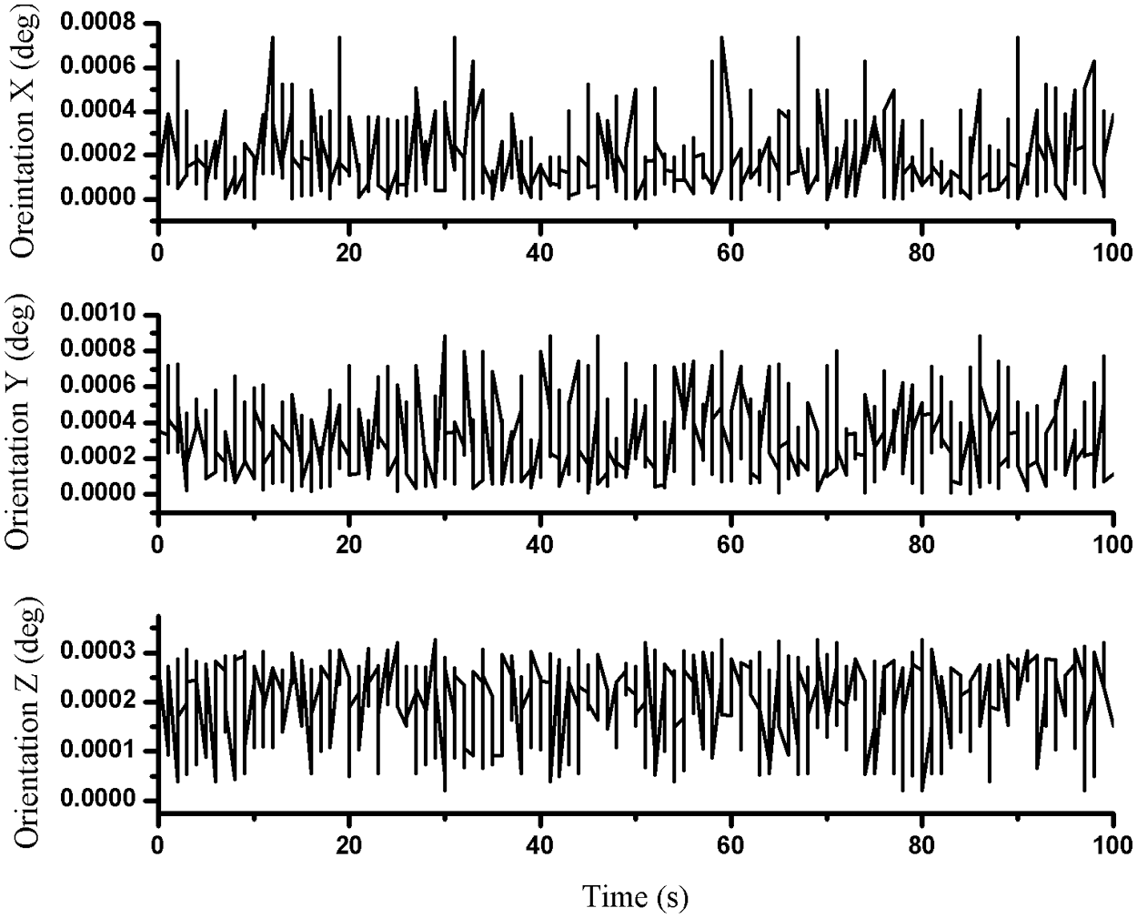
Figure 6: Test measurements of orientation estimation

A random movement of the IMU device was applied to test the feasibility of the developed algorithm. The filtering system proved its efficiency to determine the exact orientation of the device including, preventing the issue of the singularity problem. Indeed, the proposed algorithm succeeded in better improving the accuracy of the sensor measurements in order to determine the accurate orientation. It also succeeded in reducing the measurement errors to achieve a maximum of 0.00031 degrees. In addition, the proposed system offers a reliable platform to enhance the TRL of satellite system, especially the ADS, including, improvement techniques for measurement accuracy.
Enormous work has been done for many years tackling the challenges related attitude determination. During this time, providing a reference material for a comprehensive overview of attitude determination activities presents a real gap, mostly for the developing countries. Thus, the main proposal of this work was conducted to provide a practical experience around low-cost sensors for enhancing knowledge about attitude determination. Besides benefit of demonstrate satellite missions, the proposed system provided a reliable platform to develop algorithm and techniques for data accuracy improvement.
Indeed, results in Tab. 4 prove the efficiency of the proposed system that tackles both, space mission accessibility and data accuracy improvement.
This work presented an example to demonstrate a low-cost solution for the demonstration of space applications such as attitude determination system. It opened the door to develop maturity of satellites subsystems and application.
With innovation and investment in research into educational devices, it can be shown that they can be a powerful tool if combined with scientific devices for professional experiences. The algorithm proposed as a result has better improved the estimation of orientation in order to consolidate the development of satellite control and orbit correction techniques. Indeed, the proposed system was tackled the problems related techniques of measurements. It is aimed to prove the efficiency of low-cost system to enhance space engineering maturity. It is succeeded in addition to reduce measurements’ errors to detect the reliable orientation.
Acknowledgement: The authors would like to thank the Taif University for funding this work through Taif University Research Supporting, Project Number (TURSP-2020/277), Taif University, Taif, Saudi Arabia.
Funding Statement: Taif University have funded this work through Taif University Research Supporting, Project Number (TURSP-2020/277), Taif University, Taif, Saudi Arabia.
Conflicts of Interest: The authors declare that they have no conflicts of interest to report regarding the present study.
1. R. Shishko and A. Robert, NASA systems engineering handbook. Vol. 6105. NASA Special Publication, pp. 1–158, 1995. [Online]. Available: https://adsabs.harvard.edu/pdf/1995NASSP6105...S. [Google Scholar]
2. P. Thakker and W. A. Shiroma, “Emergence of Pico-and Nanosatellites for atmospheric research and technology testing,” Aeronautical Journal, American Institute of Aeronautics and Astronautics, vol. 115, pp. 411, 2010. [Google Scholar]
3. A. Nylund and J. Antonsen, “CanSat-general introduction and educational advantages,” in Proc. of the 18th ESA Symp. on European Rocket and Balloon Programmes and Related Research, Visby, pp. 1–3, 2007. [Google Scholar]
4. R. Walker, P. Galeone, H. Page, A. Castro, F. Emma et al., “ESA hands-on space education project activities for university students: Attracting and training the next generation of space engineers,” in Education Engineering (EDUCON). IEEE, Madrid, Spain, pp. 1699–1708, 2010. [Google Scholar]
5. T. Wang and R. Vandeberg, “Norwegian CanSat competition pilot,” in Proc. of the 19th ESA Symp. on European Rocket and Balloon Programmes and Related Research, Bad Reichenhall, 2009. [Google Scholar]
6. S. Nakasuka, “CanSat lecture CanSat lecture–Its educational significance,” 2013. [Online]. Available: http://www.unisec-global.org/pdf/1/2_Nakasuka.pdfAccessed on 2021. [Google Scholar]
7. R. Kawashima, “CanSat leader training program: Past, present and future,” Ciencia UANL, vol. 19, pp. 76–82, 2016. [Google Scholar]
8. A. Colin, “A pico-satellite assembled and tested during the 6th CanSat Leader Training Program,” Journal of Applied Research and Technology, vol. 15, no. 1, pp. 83–91, 2017. [Google Scholar]
9. R. P. Ramadhan, S. Putri and M. I. C. Latukolan, “Prototype of CanSat with auto-gyro payload for small satellite education,” in 13th Int. Conf. on Telecommunication Systems, Services, and Applications (TSSA), IEEE, Bali, Indonesia, pp. 243–248, 2019. [Google Scholar]
10. K. Nakaya, S. Tsurumi, H. Sawada, M. Mori, K. Ui et al., “Titech Cansat project: Sub-orbital flight and balloon experiment,” Journal of Space Technology and Science, vol. 16, pp. 1–9, 2000. [Google Scholar]
11. G. Hasan, K. Hasan, R. Ahsan, T. Sultana and R. C. Bhowmik, “Evaluation of a low-cost MEMS IMU for indoor positioning system,” International Journal of Emerging Science and Engineering, vol. 1, pp. 70–77, 2013. [Google Scholar]
12. G. G. Redhyka, D. Setiawan and D. Soetraprawata, “Embedded sensor fusion and moving-average filter for Inertial Measurement Unit (IMU) on the microcontroller-based stabilized platform,” in Int. Conf. on Automation, Cognitive Science, Optics, Micro Electro-Mechanical System, and Information Technology (ICACOMIT), IEEE, Bandung, Indonesia, pp. 72–77, 2015. [Google Scholar]
13. L. Russell, A. L. Steele and R. Goubran, “Low-cost, rapid prototyping of IMU and pressure monitoring system using an open source hardware design,” in IEEE Int. Instrumentation and Measurement Technology Conf. Proc., Graz, Austria, pp. 2695–2699, 2012. [Google Scholar]
14. A. Khosravian and M. Namvar, “Globally exponential estimation of satellite attitude using a single vector measurement and gyro,” in 49th IEEE Conf. on Decision and Control (CDC), IEEE, Atlanta, GA, USA, pp. 364–369, 2010. [Google Scholar]
15. Y. Guan and S. Xinmin, “Sensor fusion of gyroscope and accelerometer for low-cost attitude determination system,” in Chinese Automation Congress (CAC), IEEE, Xi’an, China, pp. 1068–1072, 2018. [Google Scholar]
16. S. G. Moghadam and M. R. Homaeinezhad, “Attitude determination by combining arrays of MEMS accelerometers, gyros, and magnetometers via quaternion based complementary filter,” International Journal of Numerical Modelling: Electronic Networks, Devices and Fields, vol. 31, pp. e2282, 2018. [Google Scholar]
17. J. Eickhoff, Onboard computers, onboard software and satellite operations: An introduction. Springer Science & Business Media, Germany, 2011. [Google Scholar]
18. H. Hellmers, A. Norrdine, J. Blankenbach and A. Eichhorn, “An IMU/magnetometer-based indoor positioning system using Kalman filtering,” in Int. Conf. on Indoor Positioning and Indoor Navigation, IEEE, Montbeliard, France, pp. 1–9, 2013. [Google Scholar]
19. N. Bai, Y. Tian, Y. Liu, Z. Yuan, Z. Xiao et al., “A high-precision and low-cost IMU-based indoor pedestrian positioning technique,” IEEE Sensors Journal, vol. 20, no. 12, pp. 6716–6726, 2010. [Google Scholar]
20. H. Ahmed and T. Muhammad, “Accurate attitude estimation of a moving land vehicle using low-cost MEMS IMU sensors,” IEEE Transactions on Intelligent Transportation Systems, vol. 18, no. 7, pp. 1723–1739, 2016. [Google Scholar]
21. M. H. Bao, Micro mechanical transducers: Pressure sensors, accelerometers and gyroscopes. Elsevier series. Netherlands, vol. 8, pp. 1–378, 2000. [Google Scholar]
22. O. J. Woodman, “An introduction to inertial navigation,” Technical Report, University of Cambridge, Computer laboratory, England, pp. 1–37, 2007. [Google Scholar]
23. M. D. Wheeler and I. Katsushi, “Iterative estimation of rotation and translation using the quaternion,” Carnegie-Mellon University, Department of Computer Science, Pittsburgh, pp. 1–17, 1995. [Google Scholar]
24. N. Metni, J. M. Pflimlin, T. Hamel and P. Soueres, “Attitude and gyro bias estimation for a VTOL UAV,” Control Engineering Practice, vol. 14, no. 12, pp. 1511–1520, 2006. [Google Scholar]
25. E. A. Wan, R. Van Der Merwe and S. Haykin, “The unscented Kalman filter,” Kalman Filtering and Neural Networks, vol. 5, pp. 221–280, 2007. [Google Scholar]
26. E. A. Wan and R. Van Der Merwe, “The unscented Kalman filter for nonlinear estimation,” in Proc. of the IEEE, 2000 Adaptive Systems for Signal Processing, Communications, and Control Symp., Lake Louise, AB, Canada, pp. 153–158, 2000. [Google Scholar]
 | This work is licensed under a Creative Commons Attribution 4.0 International License, which permits unrestricted use, distribution, and reproduction in any medium, provided the original work is properly cited. |