DOI:10.32604/csse.2023.025615
| Computer Systems Science & Engineering DOI:10.32604/csse.2023.025615 | |
| Article |
Novel Sensing Hole Recovery with Expanded Relay Node Capability
1Department of IT Convergence Software, Seoul Theological University, Bucheon, 14754, Korea
2Department of Electrical Engineering, Incheon National University, Incheon, 22012, Korea
*Corresponding Author: Woochan Lee. Email: wlee@inu.ac.kr
Received: 30 November 2021; Accepted: 19 January 2022
Abstract: The occurrence of ‘sensing holes’ not only hinders seamless data collection but also leads to misinterpretation of information in certain areas under extensive data analysis. In order to overcome this, various sensor relocation strategies have been proposed, but the existing relocation strategies revealed problems such as the ping-pong, shaded area, network disconnection, etc. This paper conducted research on relocation protocols in a distributed environment that is very suitable for real-world situations and efficiently recovering the problem of sensing holes. First, a simulation was performed on the distribution of the shaded area for data collection, which is a problem with the existing representative relocation protocol. After that, a data collection capability was newly added to the relay node, which had been in charge of only communication between cluster zones so far, and with this additional functionality, the performance of the revised sensor relocation algorithm was dramatically improved to overcome the existing problems. In addition, the performance and validity of the proposed algorithm were verified through various simulations.
Keywords: Hopping sensor; mobile internet of things; relocation protocol; relay node; simulation
Big data technology tends to be necessary only in collecting and analyzing vast amounts of data [1]. However, since the volume of data required is usually huge, it is challenging to find a place to collect data without problems. Therefore, a technology capable of continuously collecting data in the observation area without defects has been studied as a significant issue in recent years. For example, in areas where severe natural disasters have occurred or areas where people cannot access, such as conflict areas, essential data can be collected using various Internet of Things (IoT) devices [2–4]. Small sensors can be mounted and distributed in unmanned aerial vehicles such as drones, but it is not easy to evenly place small IoT devices throughout the observation area through spraying from drones. As a result, it is difficult to collect important data representing the region of interest, and continuous collection of inaccurate data may exhaust the energy of small devices, resulting in unexpected device defects. As such, a specific area where data collection is no longer possible is defined as a ‘sensing hole’ [5]. In the worst case, communication of the entire network may be cut off, making it impossible to collect data.
An ideal way to recover the sensing hole is to relocate the mobile IoT sensing device directly to the sensing hole to enable data collection. Early research on mobile sensors was a wheel-based method. However, the wheel movement method is limited because movement in areas with many obstacles is not free. Thus, IoT hopping sensor movement-based relocation methods have been proposed in which sensors jump and move in the desired direction. Since hopping sensor nodes move by jump, they are straightforward to move in areas such as rocks and sand. In addition, since data can be transmitted while jumping, the radius of data transmission can be adjusted. For example, it has been studied that a sensor node jumping 1 m from the ground can increase it by about six times compared to the communication radius on the ground [6], and in the paper [7], the authors also implemented projectiles to implement hopping sensors directly.
Various hopping sensor rearrangement algorithms have been proposed in recent decades. The first representative paper [8] proposed a method of recovering the sensing hole by rearranging the hopping sensor node in the shortest path cluster zone from the sensing hole. In addition, the method of relocating hopping sensors according to the degree of obstacles was first studied [9]. However, various studies [10,11] in this period tend to establish paths for relocation, assuming all cluster headers or nodes can use all information from the entire network. In other words, it makes an unrealistic assumption that it is grasping the location and degree of obstacles of nodes in each area. No matter how small the network area is, it is practically impossible for all cluster headers to exchange status information and set paths in real-time.
Recently, the authors solved this problem for the first time in their paper [12]. All sensor nodes do not need information about the surrounding sensor nodes and the entire network structure. It is a distributed networking-based rearrangement protocol in which the header of the sensing hole recovers the sensing hole by requesting sensor nodes necessary to overcome the sensing hole state from neighboring cluster headers. However, there are various limitations to the initial relocation protocol. First, a phenomenon may occur in which specific nodes that give the fastest response among neighboring clusters are repeatedly used to request ‘required nodes’ only from specific adjacent clusters. This phenomenon may also cause a ping-pong problem (a problem in which cluster headers of neighboring specific sensing holes repeatedly request required sensors from each other). In addition, even when the sensing hole was recovered, hopping sensor nodes tended to move to a range near the cluster header. It seems that the sensing hole has been restored simply by increasing the number of nodes, but it is not appropriate to collect data that can examine the characteristics of the entire cluster zone due to the restricted sensing region. The paper [13] solved this ping-pong problem and distributed sensors evenly in the cluster zone.
In this paper, problems with the previously proposed relocation protocol were identified, and the relocation protocol was further improved. In other words, even if the previous protocol could continuously collect data by overcoming the sensing hole, it was not possible to collect data evenly throughout the zone due to the limited role of relay nodes. This paper first implemented relay nodes to collect data, not just to deliver messages to neighboring cluster headers. The number of messages that occur when relay nodes do not collect data was also checked. In the performance evaluation part, the impact of the previous problems was analyzed, and the performance improvement of the currently improved relocation protocol was confirmed.
This paper consists of the following. Section 2 describes related studies, and Section 3 explains improved hopping sensor relocation methods. Section 4 demonstrates simulation and performance evaluation, and finally, Section 5 concludes.
The authors have conducted various studies in recent years [12–17], proposing realistic distributed environment-based relocation protocols. This section describes primary considerations to understand the improved relocation protocol proposed in the next section. Moreover, the relocation protocol to be compared is also briefly described to help understand this study further.
As shown in Fig. 1, data can be collected after spraying IoT hopping sensors using unmanned aerial vehicles in areas difficult for humans to access. All sensors initially deployed can be divided into several suitable cluster zones with various clustering algorithms [18]. The sensor at the center of each cluster zone is elected as a “cluster header” (H1, H2, …), sensors in the same zone as the cluster header are referred to as “member nodes” (M1, M2, …). The header periodically communicates to manage information about its member nodes. Here, it is assumed that appropriate clustering and header selection use various well-known algorithms, and further discussion is omitted because this is not the subject of this paper.

Figure 1: A simple example of the representative relocation protocol [12]
The hopping sensor can jump to communicate with neighboring sensors within a transmission radius, and each sensor may know its location (coordinate) using a Global Positioning System (GPS) unit. In Fig. 1, the radius of hopping sensor transmission on the ground is indicated by a blue line, and a red line indicates the maximum communication radius by jumping to the highest. The maximum transmission area of radio waves transmitted by the cluster header jumping to the highest level is defined as a ‘cluster zone,’ and direct communication between cluster headers is likely to be impossible. The area overlapping the cluster zones, i.e., some member nodes near the maximum transmission radius of the specific cluster header, are likely to communicate with two or more cluster headers. Such a member node is referred to as a ‘relay node,’ and the role of the relay node serves to transfer data in the middle for communication between cluster headers.
If a sensing hole occurs due to a lack of sensor nodes required for data collection in a cluster zone, the header requests the neighboring cluster zone to rearrange the member nodes required for sensing hole recovery. Fig. 1 is a simple example of the most representative relocation protocol and is as follows. The proposed protocol deletes the use of RELAY and RELAY-ACK messages. This is because using these messages results in shortest path-based requests, which are likely to cause continuous ping pong problems with the continuous use of certain relay nodes. To solve the ping pong problem, paper [16] generated a timer for transmitting the RELAY-ACK message when receiving the RELAY message from each relay node. In addition, in the paper [13], when receiving a RELAY-ACK message from each cluster header, a queue was used to manage the priority for selecting the relay node. In the paper [17], the success rate of movement of member nodes for each relay node in the cluster header was used as a random variable for relay node selection.
In each cluster zone, cluster headers periodically broadcast HELLO messages to continuously determine the number of sensor nodes in their cluster zone. The member nodes respond to their state to their header, and if there is more than one header, notify them using a HELLO-ACK message that they are a relay node. When checking the number of member nodes less than a certain number as determined in the initial network policy, the cluster header determines that its zone has become a sensing hole. In Fig. 1, it is determined that the cluster header H3 has become a sensing hole by itself, and a brief look at the rearrangement strategy performed to recover it is as follows.
In Step 1, the cluster header H3 multicasts a RELAY message to all relay nodes (R2 and R3) to request a member node from any of the neighboring cluster zones (Cluster Zones 1 and 4). In Step 2, each relay node immediately sends a RELAY-ACK message, and it is assumed that the response of R2 arrives at H3 the fastest. The response of R3 to be received later is immediately ignored. In Step 3, the cluster header H3 delivers a REQuest (called REQ) message to the selected relay node R2 to request one sensor. In Step 4, the relay node R2 delivers the REQ message from the cluster header H3 to another cluster header, H1. In Step 5, cluster header H1 sends an advertisement message to its zone members, and the members respond to the cluster header with their location and remaining energy. Cluster header H1 selects M3 as a hopping sensor member node that can be moved to a neighboring zone inside its zone and sends a MOVE message to move to Cluster Zone 3. Upon receiving the message, the member node M3 moves to a neighboring sensing hole cluster zone. After a while, in Step 6, the cluster header H1 broadcasts the HELLO message and detects that its zone has also become a sensing hole. Similarly, the H1 sends a REQ message requesting one sensor to the relay node R1. If R2 is selected as the relay node here, H2 again has a ping pong problem of continuously requesting a member from the cluster header H1. Finally, one additional sensor is relocated inside each cluster zone, resulting in the recovery of all sensing holes in the entire network.
3 The Proposed Relocation Protocol
In this section, we analyze the problems in the representative relocation protocols and propose advanced relocation protocols to improve them. In previous research, the nodes excluding the cluster header were classified as member nodes. A member node capable of communicating with two cluster headers is called a relay node and is assigned to deliver messages between cluster headers. The relay nodes to retain communication reliability are not given a role in data collection, but the remaining member nodes are assigned to perform data collection and movement between clusters. Although the sensing hole recovery is facilitated as the role of the relay nodes, some shaded area for data collection occurs.
We assume that a simple rectangular grid is shown in Fig. 2. Let us consider that the communication radius of the cluster header on the ground is r and that the maximum transmission radius of the cluster header while jumping could be

Figure 2: A shaded area for data collection
Therefore, the role of data collection should be assigned to the relay node. After data collection of the relay node, jumping must be performed to transmit data to the cluster header; thus, the energy consumption of the relay node would be very high. Since the current relay nodes could be failed due to rapid energy consumption, some member nodes should play the role of a relay node. Thus, the destination of the moving member node should not be limited to the periphery of the cluster header but should be designated as a whole cluster zone. In order to collect data that can examine the characteristics of the entire zone, it is desirable to modify the destination information of the MOVE message, which the moving members can be evenly distributed as much as possible. Thus, the coordinate (x, y) of the destination information sent by the supplier cluster header to the selected members is virtually created as following Eq. (1).
where, (xH, yH) is the destination coordinate, rm is a maximum communication radius when the header jumps highly, and rnd is a random real number between 0 and 1.
Figs. 3 and 4 show the message flows for the operation of the proposed protocol. We comply with the message formats of the paper [12] as much as possible. In Fig. 3, the message flow will be described in that the clustering is completed and the header is elected. In Step 1, Cluster Header 1 broadcasts the HELLO message, and the helloMsgTimer (hello messenger timer) is set for periodically broadcasting. Nodes 1 and 5 send HELLO-ACK messages as soon as they have received HELLO messages from their cluster. Here, they set to “false” to express that each node has contacted only one cluster header up to now. After a while, the timer is terminated in Step 2, and Cluster Header 1 updates nodes’ information in its own zone. A cluster header determines whether or not its zone is a sensing hole. In this scenario, we assume that a sensing hole occurs when there are less than two nodes, and it is currently not a sensing hole state.

Figure 3: A procedure of the proposed relocation protocol (1/2)

Figure 4: A procedure of the proposed relocation protocol (2/2)
In Step 3, Cluster Header 2 broadcasts a HELLO message as Header 1 in Step 2. Sensor node members 2, 3, and 4 reply to HELLO-ACK messages by setting “false,” however, Node 1 is currently connected to Header 1; thus, “true” is set to express Node 1 as a relay node. After the timer is terminated, Header 2 updates the information of node members in its zone and recognizes that its zone is not a sensing hole. In Step 4, in response to the broadcast of the HELLO message, Cluster Header 1 determines that Node 1 is a relay node. Here, we assume that Node 5 is a fault due to energy exhaustion. In Step 5, Cluster Header 1 checks that node members are less than two. The header determines that a sensing hole occurs in its zone. The RELAY and REALY-ACK messages were used in [12] for choosing a neighbor cluster zone to request member nodes; however, the ping-pong problem frequently occurred. Several schemes solve the problem [13,16]; however, we will use random variables that reflect the characteristics of relay nodes in [17]. Cluster Header 1 sends a REQ message to the relay node 1 to request a node member in the neighbor cluster zone. The relay Node 1 immediately delivers the REQ message to another Cluster Header 2.
In Step 6, Cluster Header 2 broadcasts an ADV message to select node members to move to the neighbor Cluster Zone 1. Each node member puts its location, remaining energy amount, etc., in the ADV-ACK message and transmits it to Cluster Header 2. In this case, the relay node, Node 1, ignores the ADV message. In Step 7, Cluster Header 2 selects a node member to move using the information of the ADV-ACK messages. The Cluster Header 2 transmits a MOVE message to Node 4 for a movement. The destination coordinate for the movement is calculated from Eq. (1).
In Step 8, Node 4 migrates to the neighboring Cluster Zone 1 and sends a NEW message directly using the new cluster header ID in the MOVE message to register itself information of Cluster Header 1. At this time, the transmission of the NEW message has to be performed simultaneously with the jump. It means that there is a possibility which the moved node could become a relay node. Cluster Header 1 sends a NEW-ACK message in response to the NEW message.
Here, we assume that the moved location of Node 4 is at an area where the maximum transmission radius areas of Cluster Headers 1 and 2 are shared. In Step 9 of Fig. 4, Cluster Header 2 transmits a periodic HELLO message, and it checks that the moved Node 4 is a relay node. In Step 10, Cluster Header 1 also confirms that Node 4 is a relay node (not a node member), and it updates the information of nodes. In Step 11, we assume that Relay Node 1 is a fault due to energy exhaustion. Since it expands the role of relay nodes to collect data in this research, this event is likely to occur highly. Thus, the HELLO message in each header may update its information of nodes. In this scenario, each header may check the failure of Node 1 and the new relay node 4.
Meanwhile, it is assumed that Cluster Header 2 has determined to add a relay node using its members due to Relay Node 1. In Step 12, Cluster Header 2 transmits a MOVE message to its Node 3 by calculating coordinates to an area where relay nodes may be located. The coordinates at this time may utilize the midpoint between the headers. Node 3 moves to the calculated destination location, and it transmits a NEW message using its current cluster header ID. In response to this, Cluster Header 2 sends a NEW-ACK message. In Step 13, Cluster Header 1 could update its relay node information, and in Step 14, Cluster Header 2 could check that Node 3 is a relay node through HELLO-ACK message.
In this section, performance evaluation is performed on the proposed relocation protocol. Tab. 1 describes the representative environment settings used in the simulation. As shown in Fig. 4a, 400 hopping sensors were randomly scattered in an area of 250 m × 250 m to collect data. A red node refers to a cluster header, a blue node refers to a relay node, and a black node refers to a node member. Fig. 4b shows the entire area as a grid. Work intensity levels for data collection were defined from Level 1 to Level 3. It is assumed that cluster ID 13, which has the darkest shaded color, is Level 3, and the events for data collection occur the most and that the outermost bright-colored grids are Level 1 and the least events occur. Considering the exponential distribution of the average
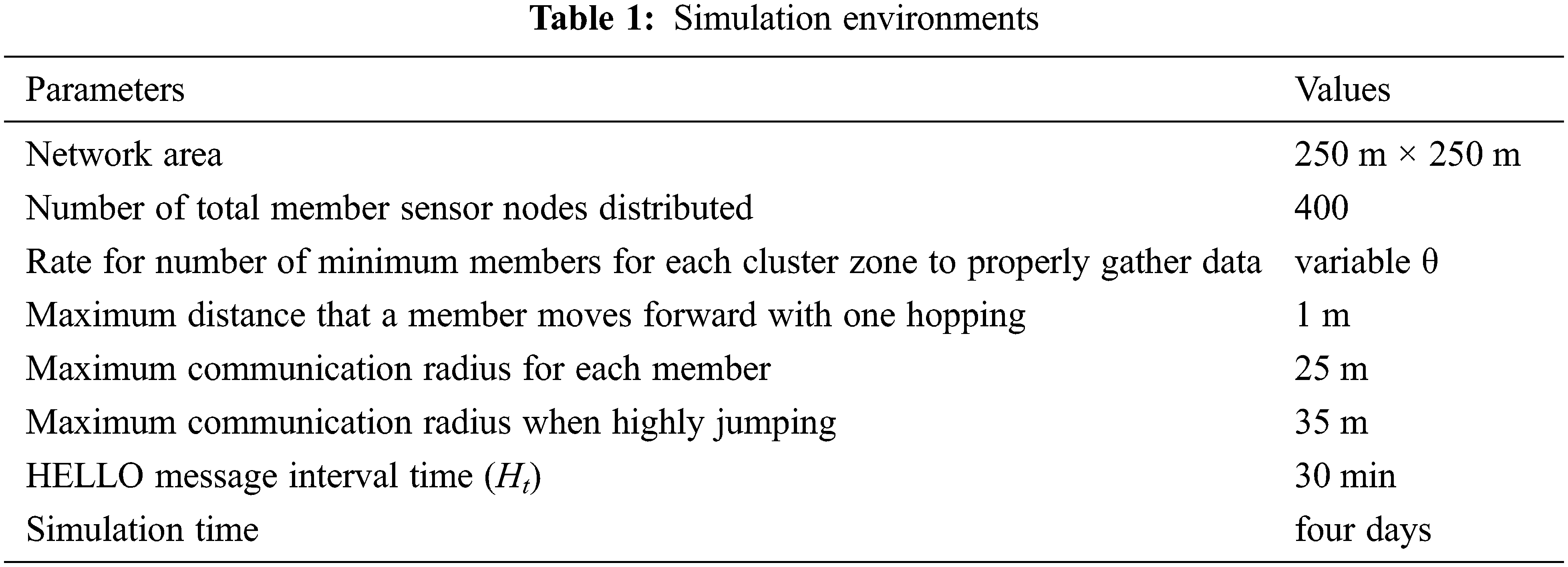
It is assumed that the transmission radius of each sensor on the ground is 25 m, and the maximum communication radius with the hopping sensor jumping to the full height is about 35 m, 25
Fig. 6 shows the measurement of the number of message occurrences in cluster 13 of Fig. 5b, which has the highest possibility of sensing holes due to the highest occurrence of events during the simulation for four days in Fig. 5a. The ‘x’ mark is the number of messages occurring during data collection when sensors are deployed and there is no mobility. The ‘o’ mark means the rearrangement protocol proposed by the paper [12]. In the previous section, due to the prohibition of data collection by relay nodes, the shaded area of one square grid is predicted to be about 57%. In Fig. 6, when looking at the number of messages occurring for almost a day, experiments confirmed that a shaded area occurs similar to the level calculated theoretically at the same time. When the rearrangement protocol is used in Fig. 6a, it can be seen that the generation of the messages for four days appears more continuously than in Fig. 6b. If the number of sensors in the sensing hole determination is high, mobility occurs a lot to overcome the sensing hole. Accordingly, network disconnection can occur early. Accordingly, network disconnection can occur early.

Figure 5: Network area

Figure 6: Number of messages generated for four days
Fig. 7 shows the number of message occurrences when a data collection task is assigned to a relay node. Protocol 1 of a triangular mark has no mobility to the relay node area, and protocol 2 of a hexagon mark gives mobility to the relay node area to replace the defective relay node. As illustrated in Fig. 7b, if the rate of determining a sensing hole is high, many defects of relay nodes occur, and protocol 2 overcomes these drawbacks and generates messages continuously for four days.

Figure 7: Number of messages generated for four days
Fig. 8 shows the network state after two days in Figs. 7b and 9 shows the network state after three days in Fig. 7b. The black node is fully charged with energy. The more energy it consumes, the more it changes from gray to white. That is, a white node means a node in which an energy defect occurs. Until Day 2, the number of message occurrences in grid 13 is similar, and the network state for the entire area is also similar. However, on Day 3, the number of message occurrences in the second protocol was high in grid 13, and it can be seen that network disconnection occurred rapidly in Fig. 9a in the distribution of nodes across the network.
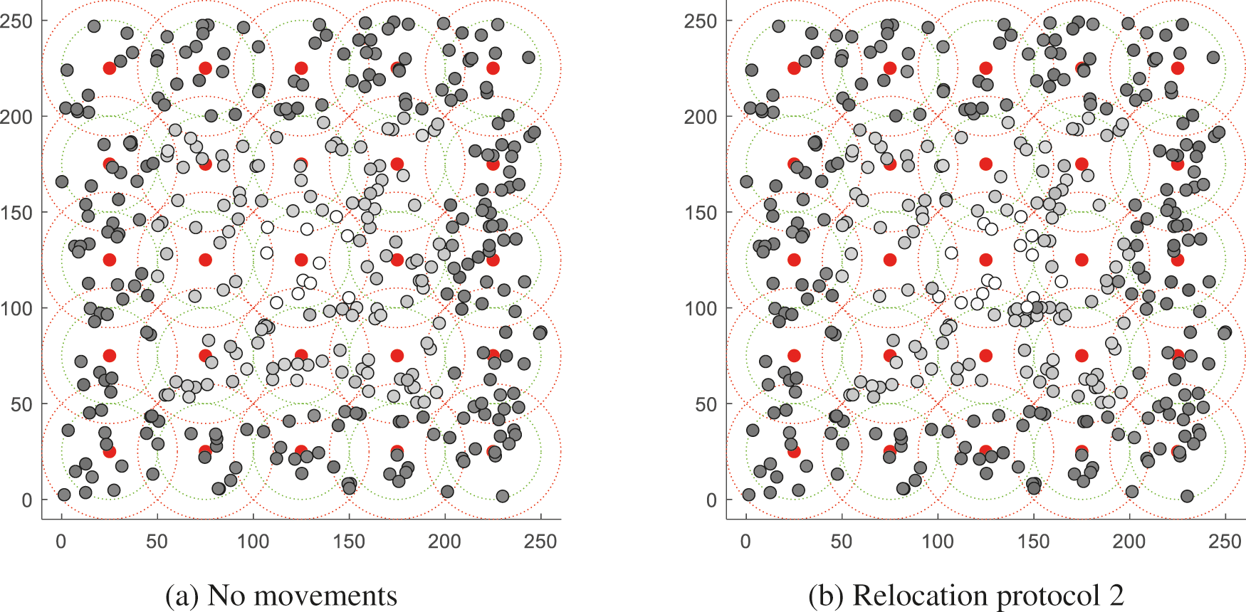
Figure 8: Network states after two days in Fig. 7b

Figure 9: Network states after three days in Fig. 7b
If a sensing hole condition in which data collection is impossible occurs due to improper placement of IoT sensor devices or energy depletion, it is most desirable to relocate the mobile sensor. Furthermore, if the deployed area is rough-surfaced, hopping sensors should be relocated to improve the success rate of the appropriate displacement, and the related research has been in progress for a long time. Most of the known relocation algorithms of the hopping sensor so far have the unrealistic (simulation-only scale) assumption that all nodes know the overall state of the whole network and each node’s current state. Our research team already proposed world-first and the most advanced relocation algorithms based on the realistic distributed network environments that completely remove the necessity of sharing all information between nodes. In the most realistic distributed environment-based relocation protocol, the cluster header of the sensing hole transmits a request message for sensor relocation to the adjacent cluster header through a specific relay node. Due to this, even if a sensor node failure in a specific area occurs, a new sensor node capable of recovering it can be moved. However, in the relocation protocol so far, the relay nodes that pass data between the cluster headers have no role in data collection. Through this, the reliability of data transmission could be improved, but there were many shaded areas where data could not be collected. Through the analysis of the shaded area, it was found that the shaded area was very vast, so the data collection was not sufficient, and then network disconnection was caused.
In this paper, pioneer research on relocation protocols in a distributed environment that is very suitable for reality is conducted. In order to remove the shadow area, the function of data collection is given to the relay node, and the representative relocation protocol is improved to overcome the defects that may occur to the relay node. Simulations demonstrated that the improved relocation protocol could collect messages while recovering the sensing hole for a long time compared to the previous protocol. In the future, a relocation algorithm that can properly respond to dynamically changing fields (such as desert, gravel field, and so on) will be further investigated.
Funding Statement: This work was supported by Incheon National University Research Grant in 2021(2021-0295).
Conflicts of Interest: The authors declare that they have no conflicts of interest to report regarding the present study.
1. W. Lee, M. Kim and J. Park, “Speed-up of the matrix computation on the ridge regression,” KSII Transactions on Internet and Information Systems, vol. 15, no. 10, pp. 3482–3497, 2021. [Google Scholar]
2. Z. A. Almusaylim, N. Z. Jhanjhi and A. Alhumam, “Detection and mitigation of RPL rank and version number attacks in the internet of things: SRPL-RP,” Sensors, vol. 20, no. 21, pp. 5997, 2020. [Google Scholar]
3. T. -B. Dang, D. -T. Le, T. -D. Nguyen, M. Kim and H. Choo, “Monotone split and conquer for anomaly detection in IoT sensory data,” IEEE Internet of Things Journal, vol. 8, no. 20, pp. 15468–15485, 2021. [Google Scholar]
4. T. -D. Nguyen, D. -T. Le, V. V. Vo, M. Kim and H. Choo, “Fast sensory data aggregation in IoT networks: Collision-resistant dynamic approach,” IEEE Internet of Things Journal, vol. 8, no. 20, pp. 15468–15485, 2021. [Google Scholar]
5. R. Kosar, E. Onur, C. Ersoy and C. Redeployment, “Based sensing hole mitigation in wireless sensor networks,” in Proc. IEEE WCNC, Budapest, Hungary, 2009. [Google Scholar]
6. F. Cintr’on, “Network issues for 3d wireless sensors networks,” Ph.D. dissertation, Michigan State University, MI, USA, 2013. [Google Scholar]
7. M. S. Kim, “Design of a transmission process for hopping sensors to enhance coverage,” M.S. thesis, Sungkyunkwan University, Suwon, Republic of Korea, 2012. [Google Scholar]
8. Z. Cen and M. W. Mutka, “Relocation of hopping sensors,” in Proc. IEEE ICRA, Pasadena, CA, USA, pp. 569–574, 2008. [Google Scholar]
9. M. Kim, M. W. Mutka and H. Choo, “On relocation of hopping sensors for rugged terrains,” in Proc. ICCSA, Fukuoka, Japan, pp. 203–210, 2010. [Google Scholar]
10. M. Kim and M. W. Mutka, “On relocation of hopping sensors for balanced migration distribution of sensors,” in Proc. ICCSA, Seoul, Korea, pp. 361–371, 2009. [Google Scholar]
11. M. Kim and M. W. Mutka, “Multipath-based relocation schemes considering balanced assignment for hopping sensors,” in Proc. IEEE/RSJ IROS, St. Louis, MO, USA, pp. 5095–5100, 2009. [Google Scholar]
12. M. Kim, S. Park and W. Lee, “Energy and distance-aware hopping sensor relocation for wireless sensor networks,” Sensors, vol. 19, no. 7, pp. 1567, 2019. [Google Scholar]
13. M. Kim, S. Park and W. Lee, “Ping-pong free advanced and energy efficient sensor relocation for IoT-sensory network,” Sensors, vol. 20, no. 19, pp. 5654, 2020. [Google Scholar]
14. S. Park, M. Kim and W. Lee, “Energy-efficient wireless hopping sensor relocation based on prediction of terrain conditions,” Electronics, vol. 9, no. 1, pp. 49, 2020. [Google Scholar]
15. S. Park, M. Kim and W. Lee, “Success rate queue-based relocation algorithm of sensory network to overcome non-uniformly distributed obstacles,” Computers, Materials & Continua, vol. 65, no. 2, pp. 1181–1201, 2020. [Google Scholar]
16. S. Park, M. Kim and W. Lee, “Uniform sensor-node request scheme for the recovery of sensing holes on IoT network,” Journal of Korea Society of Digital Industry and Information Management, vol. 16, no. 4, pp. 9–17, 2020. [Google Scholar]
17. M. Kim and W. Lee, “Adaptive success rate-based sensor relocation for IoT applications,” KSII Transactions on Internet and Information Systems, vol. 15, no. 9, pp. 3120–3137, 2021. [Google Scholar]
18. A. S. Rostami, M. Badkoobe, F. Mohanna, H. Keshavarz, A. A. R. Hosseinabadi et al., “Survey on clustering in heterogeneous and homogeneous wireless sensor networks,” The Journal of Supercomputing, vol. 74, pp. 277–323, 2018. [Google Scholar]
 | This work is licensed under a Creative Commons Attribution 4.0 International License, which permits unrestricted use, distribution, and reproduction in any medium, provided the original work is properly cited. |