DOI:10.32604/csse.2023.026046
| Computer Systems Science & Engineering DOI:10.32604/csse.2023.026046 | |
| Article |
A Steganography Based on Optimal Multi-Threshold Block Labeling
1Department of Information Engineering and Computer Science, Feng Chia University, Taichung, 407, Taiwan
2Department of Electronic Engineering, National Quemoy University, Kinmen, 892, Taiwan
*Corresponding Author: Ji-Hwei Horng. Email: horng@email.nqu.edu.tw
Received: 14 December 2021; Accepted: 25 January 2022
Abstract: Hiding secret data in digital images is one of the major research fields in information security. Recently, reversible data hiding in encrypted images has attracted extensive attention due to the emergence of cloud services. This paper proposes a novel reversible data hiding method in encrypted images based on an optimal multi-threshold block labeling technique (OMTBL-RDHEI). In our scheme, the content owner encrypts the cover image with block permutation, pixel permutation, and stream cipher, which preserve the in-block correlation of pixel values. After uploading to the cloud service, the data hider applies the prediction error rearrangement (PER), the optimal threshold selection (OTS), and the multi-threshold labeling (MTL) methods to obtain a compressed version of the encrypted image and embed secret data into the vacated room. The receiver can extract the secret, restore the cover image, or do both according to his/her granted authority. The proposed MTL labels blocks of the encrypted image with a list of threshold values which is optimized with OTS based on the features of the current image. Experimental results show that labeling image blocks with the optimized threshold list can efficiently enlarge the amount of vacated room and thus improve the embedding capacity of an encrypted cover image. Security level of the proposed scheme is analyzed and the embedding capacity is compared with state-of-the-art schemes. Both are concluded with satisfactory performance.
Keywords: Reversible data hiding; encryption image; prediction error compression; multi-threshold block labeling
With the rapid development of digital multimedia, the information security of multimedia becomes a tremendous challenge. As a fundamental form of multimedia, the information security of digital images has drawn much attention. Therefore, many technologies have been developed to increase image security, such as watermark [1,2], secret sharing [3,4], and data hiding [5–26]. As a crucial branch of the image security field, the data hiding technology hides secret information in a cover image while preserving its visual appearance. Thus, it is widely applied in copyright protection, integrity verification, and access control. During the last decades, there are multitudinous data hiding methods have been proposed, which are classified into reversible data hiding (RDH) [5–7] and irreversible data hiding [8–10]. The irreversible data hiding causes permanent damage to the carrier image, which is not applicable to the applications that cannot tolerate any distortion, such as law forensics and medical images. On the contrary, reversible data hiding recovers the carrier image without any distortion after extracting the secret data, so it has wider use. According to the different operation domains of the RDH, which can be further divided into four classes: the spatial domain-based RDH [3–8], the frequency domain-based RDH [11–13], the compressed domain based-RDH [14,15], and the encryption domain-based RDH [16–27] approaches.
Since the continuous improvement of hardware computing efficiency and network transmission speed, the images from the sensitive applications such as secure remote sensing and medical services are uploaded to the cloud. The cloud service provider embeds additional data to the unloaded images. However, consider the confidentiality of those images, some privacy protection techniques must take to prevent the exposure of the original image. Thus, the reversible data hiding in encrypted images (RDHEI) aroused heated discussions in the security field. In this application context, the RDHEI method consists of three participants, the content owner, the data hider, and the recipient. On the content owner’s side, the cover image is encrypted before uploading to the cloud. On the data hider’s side, the secret data is embedded into the obtained encrypted image. On the recipient’s side, extracts the secret data, restores the cover image, or executes both activities according to his/her specific permissions. Based on the order of image encryption and vacating room for data embedding, the existing RDHEI schemes are classified into two types, reserving room before encryption (RRBE) [16–20] and vacating room after encryption (VRAE) [21–27].
In the RRBE methods, the content owner reserves room for data embedding before image encryption. In 2013, the first RRBE based scheme is proposed by Ma et al. [16], which divides the cover image into smooth regions and complex regions according to the texture characteristics. After that, the LSBs in the smooth regions are replaced with the secret data in the data hiding side. In 2019, Chen et al. [17] proposed a novel RDHEI method that compresses the bit-planes of the original image by bit-plane rearrangement (BPR) and the extended run-length coding (ERLC) to vacate the room for data embedding. In [18], based on adaptive prediction-error labeling (APL), a high-capacity and secure RDHEI method is proposed by Wu et al., which takes advantage of the Laplacian-like distribution of prediction errors to increase the reserved room before encryption. In Xu et al. method [19], an RDHEI method based on vector quantization (VQ) prediction and parametric binary tree labeling (PBTL) is proposed, which adaptively sets the labeling parameters to maximize the vacating room for data embedding. Later, based on the hierarchical quad-tree coding and bit-plane compression, Liu et al. [20] proposed an RDHEI method which minimizes image file size and improves the embedding capacity. Although the relationship between adjacent pixels is fully utilized to embed secret data in the RRBE methods, the exposed label bits may leak information of the cover image.
In the VRAE methods, the content owner encrypts the cover image without any preprocessing. In short, the spare room is vacated on the data hider side, which is more secure for the carrier image. In 2014, a VRAE based RDHEI method is proposed by Wu et al. [21], pixels inside the image are classified into the qualified set or the forbidden set like a chessboard, where the qualified pixels are exploits for data embedding while the forbidden pixels are not. In 2015, based on the idea of cross-division and additive homomorphism, Li et al. [22] propose an RDHEI method, which has better embedding performance. In Xiao et al. method [23], a separable RDHEI method based on pixel value ordering (PVO) is proposed, where the additive homomorphism ensures that the performance of PVO in encrypted domain is close to that in plain domain. In 2018, Qin et al. [24] proposed an adaptive reversible data hiding scheme, which classifies encrypted blocks into two sets corresponding to smooth and complex regions and embeds more bits into the smooth blocks. Based on the most significant bit (MSB) prediction, Puteaux et al. [25] proposed an RDHEI method, which exploits the MSB of pixels in the available block for data hiding, while the MSB of pixels in the unavailable block are adopted to record the prediction error location. Later, according to the characteristics of the image block, the method proposed by Bhardwaj et al. [26] further divides blocks into sub-image blocks to increase the embedding capacity. In 2020, Chen [27] proposed a novel method, which is based on the compression of pixel differences, where the prediction errors are recorded by the Huffman coding.
We propose an efficient reversible data hiding scheme in encrypted images based on an optimal multi-threshold block labeling, which provides a high capacity for data embedding. Our contributions can be summarized as follow.
(1) The in-block pixel correlation is preserved, while image privacy is protected by encryption.
(2) The PER, OTS, and MTL methods are exploited to compress the bit-planes of prediction error and thus maximize embedding capacity. Experimental results show that the embedding capacity of our scheme outperforms state-of-the-art schemes.
(3) Data extraction and image recovery processes are separable. The authorities can be granted with different keys.
The remaining parts of the scheme are organized as follows. The details of our scheme are introduced in Section 2. Section 3 expounds on the experimental results. In the end, the conclusions of this scheme are obtained in Section 4.
In this section, the details of the proposed scheme are described as follows. Fig. 1 shows the framework of the scheme. In our scheme, there are three participants, namely content owner, data hider, and receiver. The content owner encrypts the original image by block permutation, pixel permutation, and block-based stream cipher processes. Then, the data hider exploits the prediction error rearrangement (PER), the optimal parametric selection (OPS), and the multi-threshold labeling (MTL) to vacate the room and embeds the secret data into the spare space. The receiver extracts the secret data using the data hiding key, restores the original image using the image encryption key, or do both according to its authority.

Figure 1: The framework of the proposed OMTBL-RDHEI scheme
2.1 Encrypted Image Generating
To protect the privacy of image content, the content owner encrypts the original image before transmitting it. The image encryption of the proposed scheme consists of block permutation, pixel permutation, and block-wise stream cipher procedures. Thus, the image encryption key that used in the encryption operation contains three sub-keys
Consider that the original image Io sized M × N is divided into k non-overlapping 2 × 2 blocks
After partitioning into blocks, these blocks are scrambled using the block permutation key
An image encryption result is shown in Fig. 2, where Fig. 2a is a standard grayscale test image of ‘Lena’; Figs. 2b–2d are the encryption results of difference phases. The histograms of Figs. 2a–2d are given in Figs. 2e–2h. As shown in Fig. 2c, the image content has been greatly damaged after the block permutation and pixel permutation. However, the histogram is still preserved as shown in Fig. 2g, which exposes the information of image. To improve security, the block-based stream cipher is conducted to further encrypt the image. For each permutated image block

Figure 2: The example of the image encryption for ‘Lena’. (a) Original ‘Lena’ image, (b) ‘Lena’ image after blocks permutation, (c) ‘Lena’ image after blocks permutation and pixels permutation, (d) final encrypted image, (e-h) histograms of (a-d)
Next, the block encryption key
In practical applications, the block permutation stream, the pixel permutation stream and the block-wise stream cipher is generated by an encryption key Ke. After the encryption procedures, the content owner uploads the encrypted image E to the cloud.
The image content is completely unreadable for the encrypted image shown in Fig. 2d, and the pixel-values are uniformly distributed as shown in Fig. 2h. This is, after our encryption process, the privacy of the cover image is well guaranteed. More details of security analysis are demonstrated in Section 3.1.
2.2 Prediction Error Rearrangement
After receiving the encrypted image E, the data hider decomposes it into 2 × 2 blocks

Figure 3: The reference pixel and reconfigurable pixels

Figure 4: The histogram of the prediction errors. (a) Lena (b) Airplane
To compress the redundant space, we decompose the absolute prediction errors

Figure 5: The example of PER
To verify the effect of our PER method, the number

Figure 6: The histogram for no. (a) Lena (b) Airplane
In this processing phase, we propose a novel block labeling method, called multi-threshold labeling (MTL), which vacates room from the encrypted image E using multiple thresholds
For an encrypted image E, the number of leading zeros
In the Fig. 7, we take two encrypted image blocks from “Lena” image to illustrate the procedure of the proposed MTL, where the applied threshold list is

Figure 7: Illustration of the proposed MTL method
For the block in Fig. 7a, the replaceable pixels are predicted using the reference pixel, and the prediction errors are obtained by Eq. (5). Then, use Eqs. (6) and (7) to obtain the prediction error streams and the sign bits. Next, the prediction error rearrangement (PER) is applied to rearrange the prediction error streams into a concatenated stream
For the block in Fig. 7b, the replaceable pixel values are predicted and rearranged as demonstrated in the figure. Since
2.4 Optimal Threshold Selection
In the MTL proposed in the previous subsection, we randomly select a set of four equally spaced thresholds to label the example block. To maximize the total vacated room of a given image, the number of indicator bits and the values of thresholds can be adjusted according to the image features. An optimal threshold selection (OTS) algorithm is proposed to optimize the threshold settings.
As shown in Algorithm 1, we fully try the possible length of indicator bits δ from 1 to 4 bits and evaluate the vacated room for all

After obtaining the optimal threshold list, the data hider is ready to hide secret data into the encrypted image. In order to demonstrate the data hiding procedure, Fig. 8 applies the optimal threshold list
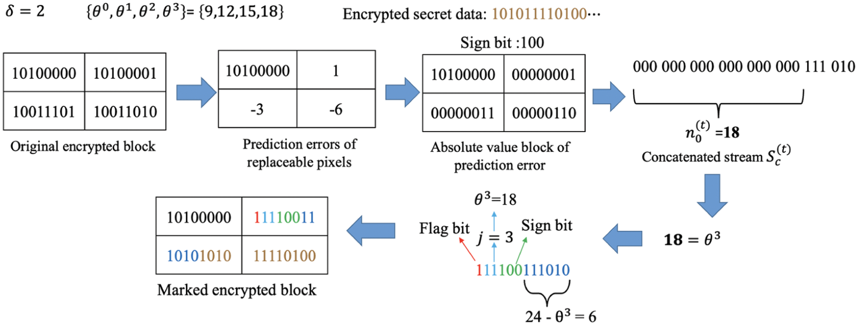
Figure 8: Illustration of the optimal multi-threshold labeling and data hiding
The optimal threshold list should be shared with the receiver to exactly decrypt image and secret data. The proposed solution is to record the required information with a fixed threshold list for a least number of leading blocks. Besides, instead of recording the complete optimal threshold list, we record the optimal parameters δopt and iopt obtained in the optimization algorithm. The complete list can be recovered with simple manipulations based on the two parameters. The least number of leading blocks which can provided

2.5 Data Extraction and Image Recovery
A recipient of the marked encrypted image can extract the secret data, restore the cover image, or do both according to his/her authorization. The data extraction and image recovery are in the reverse order of the encryption and embedding procedure.
When the recipient holds the data-hiding key Kh, he/she can accurately extract the secret data. The procedure is shown as the Algorithm 3. In our method, the marked encrypted image

When the recipient holds the encryption key Ke, he/she can losslessly restore the original image. The procedure is shown as the Algorithm 4. Note that, the data extraction is exploited to obtain the
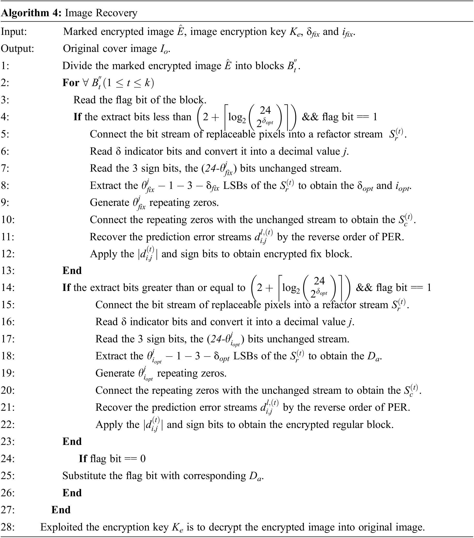

Figure 9: The reverse order of PER
Fig. 10 shows the example of data extraction and image recovery for the marked regular image block with the optimal threshold list

Figure 10: Data extraction and image recovery for marked regular encrypted block
As shown in Fig. 10a, when the recipient holds the data-hiding key Kh, he/she read the flag bit ‘1’ at first. Then, connect the bit stream of replaceable pixels into a refactor stream “111100111010101011110100”. Next, read δ = 2 indicator bits “11” and convert it into a decimal value “3”. After that, extracts the
As shown in Fig. 10b, when the recipient holds the encryption key Ke, he/she read the flag bit ‘1’ at first. Then, connect the bit stream of replaceable pixels into a refactor stream “111100111010101011110100”. Next, read δ = 2 indicator bits “11” and convert it into a decimal value “3”. After that, read the 3 sign bits “110”, the (24-
3 Experimental Result and Discussions
To evaluate the performance of the proposed scheme, the experiments including security analysis, embedding capacity and comparison are conducted. For these experiments, we select six standard gray-scale images as test images: Airplane, F16, Lena, Peppers, Barbara, and Elaine as shown in Fig. 11. Moreover, the databases BOWS-2 [28] and BOSSbase [29] are applied to further verify the generality of the scheme.

Figure 11: The test images of the proposed scheme
As shown in Fig. 2h, the pixel values in the encrypted image are even and chaotic. In order to further test the pixel distribution of the image generated in different phases, we conduct Lena as an example to present the corresponding experiment results as shown in Fig. 12.

Figure 12: Results in different phases for ‘Lena’. (a1) Original ‘Lena’ image, (b1) encrypted ‘Lena’ image, (c1) embedded encrypted ‘Lena’ image (d1) recovered ‘Lena’ image, (a2-d2) histograms of images a1-d1, (a3-d3) pixel distributions of the images a1-d1
In the Fig. 12, the original image (a1) and the recovered image (d1) are the same, which mean that the proposed scheme can recover the original image losslessly. In additional, as we can see, the pixel distribution of encrypted image and embedded encrypted image are even and chaotic that is difference from the distribution of original image. Thus, we can conclude that it is almost impossible to obtain the information of the original image from the encrypted image by statistical attack.
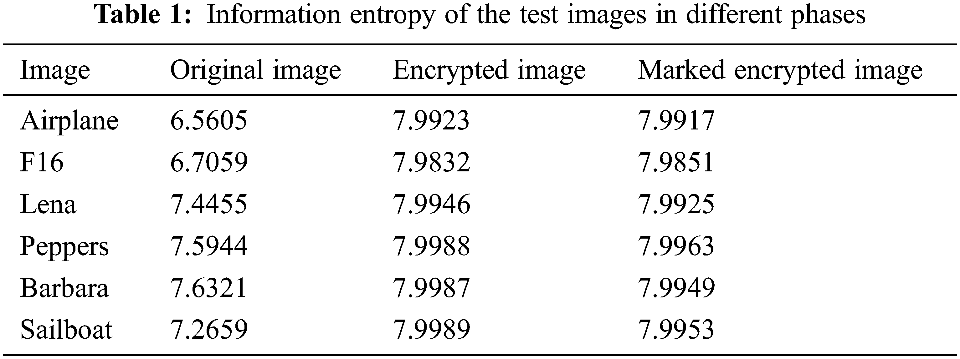
To further explore the security of the proposed scheme, we applied the information entropy to measure the randomness of the images in different phases. The information entropy can be obtained by Eq. (8), where s represents the gray level of image pixels, p(si) represents the relative probability of a particular gray level
To evaluate the embedding capacity of the proposed scheme, some experiments are conducted in this section. A comparison with state-of-the-art schemes is also presented. The embedding capacity of a cover image is measured with the embedding rate Cbr in bits per pixel defined by
where N is the amount of embedded data in bits and n(I) is the number of pixels in the cover image.
We first verify the effectiveness of the OTS method. A random threshold list, a fixed equidistant threshold list, and the optimal threshold list obtained by our method are applied to the image ‘Lena’, with δ = 2 and δ = 3, the corresponding embedding rates are listed in Tab. 2. As shown in the table, the optimal threshold list obtain by our OTS method significantly outperforms the random selected and the fixed equidistant lists.

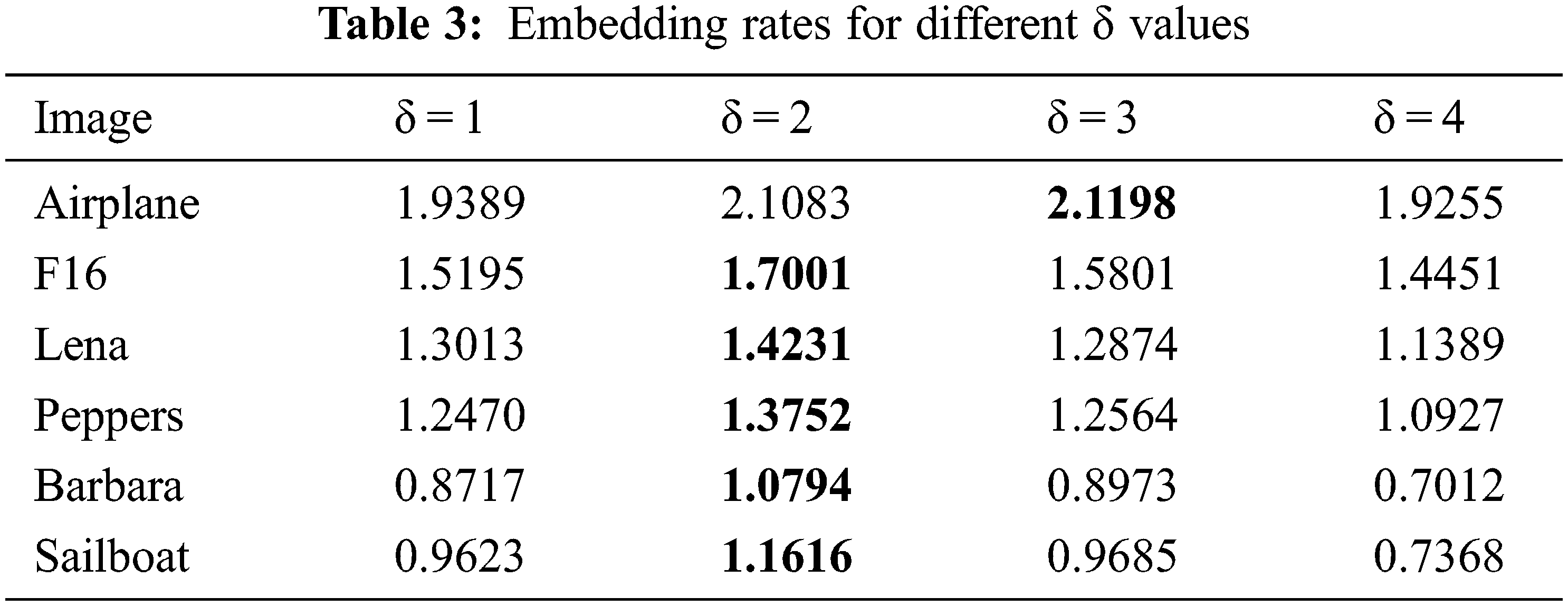
The embedding rates of the proposed scheme for different δ values are listed in Tab. 3. The embedding rate at δ = 2 is the best for most of the test images and exceeds 1 bpp for all. The only exceptional case is the image ‘Airplane’, whose best value occurs at δ = 3. An image with a smooth variation of pixel values has a larger dynamic range of prediction error. More threshold levels can improve its compression ratio of prediction error.
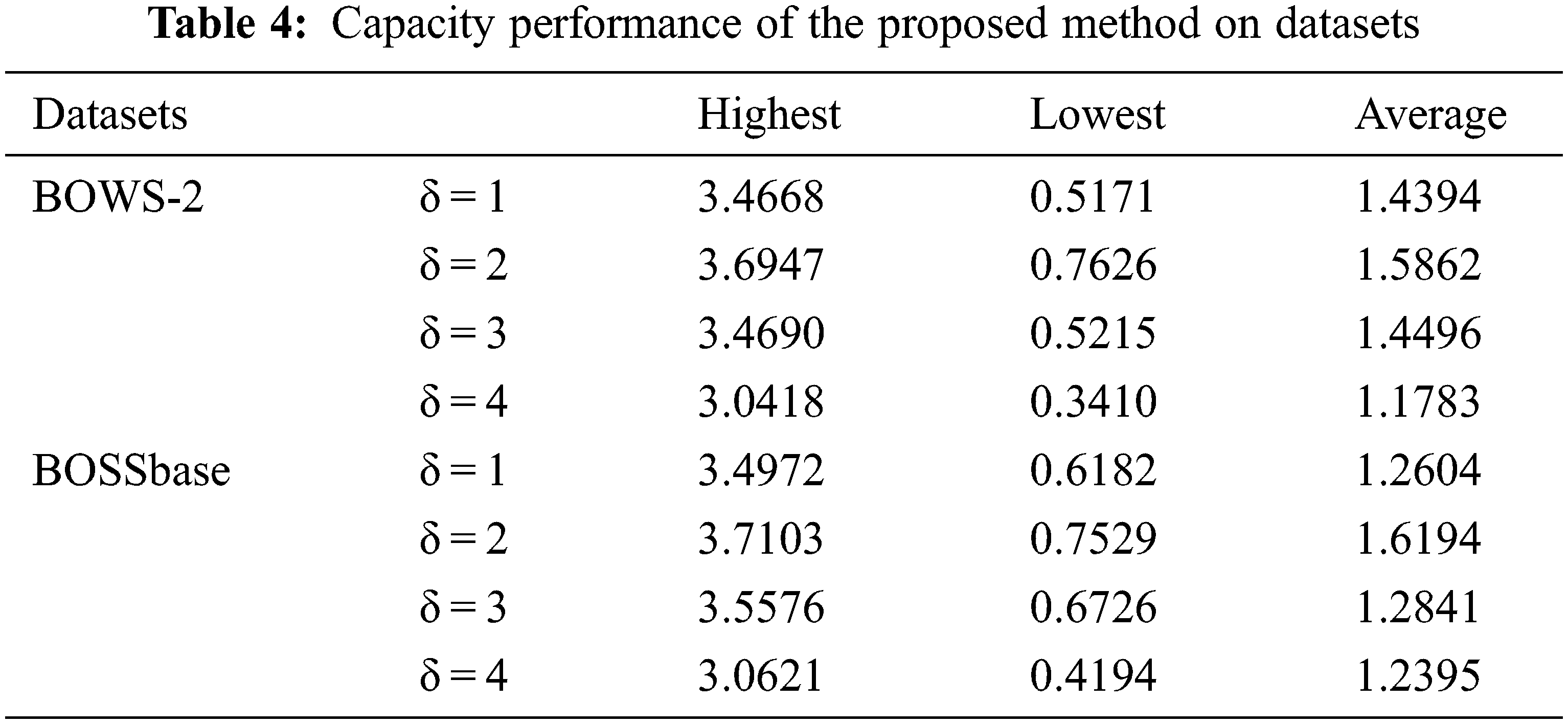
Next, to verify the generality of our scheme, the databases BOWS-2 [28] and BOSSbase [29] are applied to measure the embedding rate. Tab. 4 demonstrate the embedding capacity performance of the proposed method on the BOW-2 and BOSSbase database. Through observation, we can find that the highest embedding rate achieve 3.6947 bpp for BOWS-2 and 3.7103 bpp for BOSSbase, and the average embedding rate achieve 1.5862 bpp for BOWS-2 and 1.6194 bpp for BOSSbase when δ = 2.
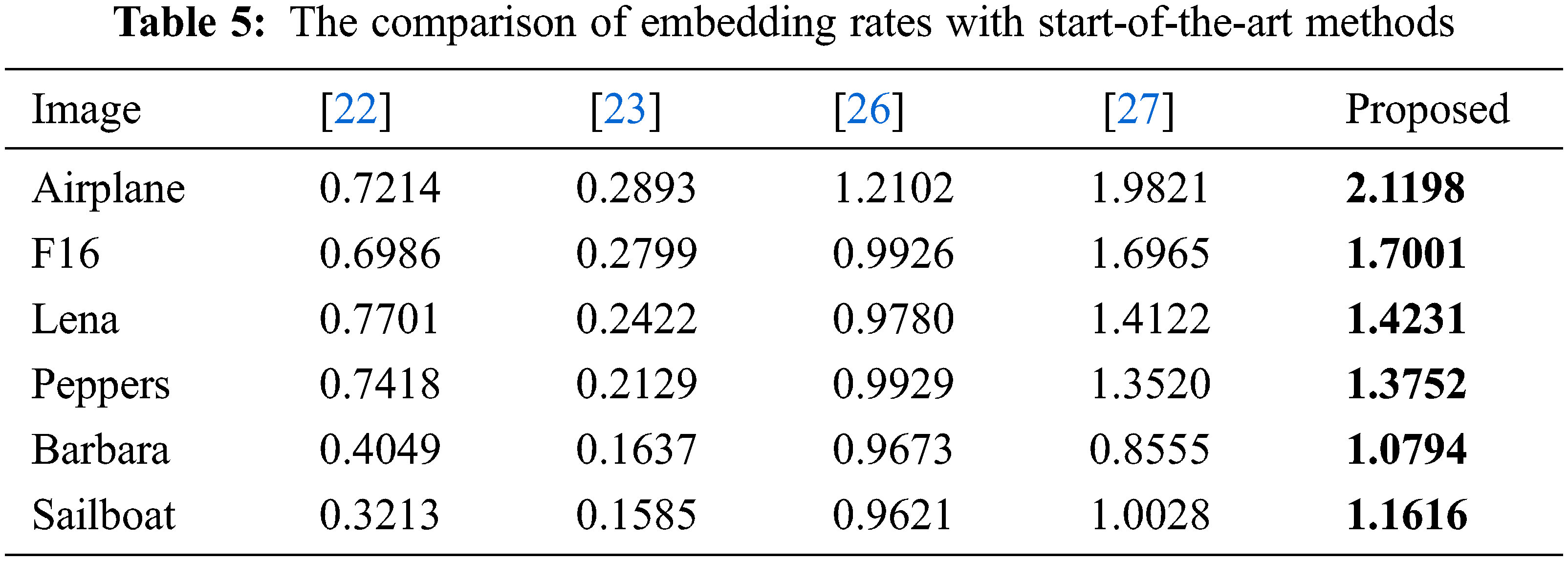
To further investigate the performance of our scheme, the proposed scheme is compared with five state-of-the-art schemes, including the Li et al. [22], the Xiao et al. [23], the Bhardwaj et al. [26], and the Chen’s [27] schemes. The comparison for the six test images is listed in Tab. 5. As shown in the table, the embedding capacity of our scheme for smooth images such as ‘Airplane’ and ‘F16’ exceeds 1.7 bpp, which is a significant improvement. In addition, the embedding capacity for complex images such as ‘Barbara’ and ‘Sailboat’ can exceed 1 bpp. A visualized bar chart corresponding to Tab. 5 is given in Fig. 13.

Figure 13: The comparison of embedding rates in bar chart
We propose a novel OMTBL-RDHEI scheme. In our scheme, the cover image is first processed by the content owner with a block-level encryption, including a block permutation, a pixel permutation, and a block-based stream cipher, which retains the in-block spatial correlation of the original image. The data hider exploits the PER method to rearrange the in-block perdition errors and obtain the concatenation streams. Then, the OPS method is applied to select the optimal threshold list. In the end, the ABL method labels all image blocks with the optimal list. The receiver extracts the embedded secret data and restores the original image without any distortion. Experiments show that the proposed scheme improves the average embedding rate to 1.5862 bpp for BOWS-2 dataset and 1.6194 bpp for BOSSbase dataset. In addition, the proposed scheme ensures a good security level. In the future, we plan to seek a more efficient image compression approach that can further increase the data embedding capacity.
Funding Statement: This research was funded by the Ministry of Science and Technology of Taiwan, Grant Number MOST 110-2221-E-507-003.
Conflicts of Interest: The authors declare that they have no conflicts of interest to report regarding the present study.
1. C. -C. Chang, C. -T. Li and Y. Q. Shi, “Privacy-aware reversible watermarking in cloud computing environments,” IEEE Access, vol. 6, pp. 70720–70733, 2018. [Google Scholar]
2. C. Qin, P. Ji, C. -C. Chang, J. Dong and X. Sun, “Non-uniform watermark sharing based on optimal iterative BTC for image tampering recovery,” IEEE Multimedia, vol. 25, no. 3, pp. 36–48, 2018. [Google Scholar]
3. C. Qin, C. Jiang, Q. Mo, H. Yao and C. -C. Chang, “Reversible data hiding in encrypted image via secret sharing based on GF(p) and GF(2^8),” IEEE Transactions on Circuits and Systems for Video Technology, 2021. http://dx.doi.org/10.1109/TCSVT.2021.3091319. [Google Scholar]
4. C. -C. Chang and C. -T. Li, “Algebraic secret sharing using privacy homomorphisms for IoT-based healthcare systems,” Mathematical Biosciences and Engineering, vol. 16, no. 4, pp. 3367–3381, 2020. [Google Scholar]
5. S. Yi and Y. Zhou, “Binary-block embedding for reversible data hiding in encrypted images,” Signal Processing, vol. 133, pp. 40–51, 2017. [Google Scholar]
6. C. -C. Chang, “Neural reversible steganography with long short-term memory,” Security and Communication Networks, vol. 2021, pp. 14, 2021. [Google Scholar]
7. C. -C. Chang, “Cryptospace invertible steganography with conditional generative adversarial networks,” Security and Communication Networks, vol. 2021, pp. 14, 2021. [Google Scholar]
8. J. -H. Horng, S. Y. Xu, C. -C. Chang and C. -C. Chang, “An efficient data-hiding scheme based on multidimensional mini-SuDoKu,” Sensors, vol. 20, no. 9, pp. 2739, 2020. [Google Scholar]
9. J. -H. Horng, J. Lin, Y. J. Liu and C. -C. Chang, “3D multilayered turtle shell models for image steganography,” Computer Modeling in Engineering & Sciences, vol. 125, no. 2, pp. 879–906, 2020. [Google Scholar]
10. C. -C. Chang, Y. J. Liu and T. S. Nguyen, “A novel turtle shell-based scheme for data hiding,” in 2014 Int. Conf. on Intelligent Information Hiding and Multimedia Signal Processing, Kita Kyushu, Japan, pp. 89–93, 2014. [Google Scholar]
11. C. -Y. Yang and W. -C. Hu, “Reversible data hiding in the spatial and frequency domains,” International Journal of Image Processing, vol. 3, no. 6, pp. 373–384, 2010. [Google Scholar]
12. H. Zhang and L. T. Hu, “A data hiding scheme based on multidirectional line encoding and integer wavelet transform,” Signal Processing: Image Communication, vol. 78, pp. 331–334, 2019. [Google Scholar]
13. F. Li, Q. Mao and C. -C. Chang, “A reversible data hiding scheme based on IWT and the sudoku method,” International Journal of Network Security, vol. 18, no. 3, pp. 410–419, 2014. [Google Scholar]
14. F. J. Huang, X. C. Qu, H. J. Kim and J. W. Huang, “Reversible data hiding in JPEG images,” IEEE Transactions on Circuits Systems for Video Technology, vol. 26, no. 9, pp. 1610–1621, 2016. [Google Scholar]
15. X. Wang, C. -C. Chang and C. -C. Lin, “Adaptive reversible data hiding scheme for AMBTC compressed images,” Multimedia Tools and Applications, vol. 79, pp. 6547–6568, 2020. [Google Scholar]
16. K. Ma, W. Zhang, X. Zhao, N. Yu and F. Li, “Reversible data hiding in encrypted images by reserving room before encryption,” IEEE Transactions on Information Forensics and Security, vol. 8, no. 3, pp. 553–562, 2013. [Google Scholar]
17. K. Chen and C. -C. Chang, “High-capacity reversible data hiding in encrypted images based on extended run-length coding and block-based MSB plane rearrangement,” Journal of Visual Communication and Image Representation, vol. 58, pp. 334–344, 2019. [Google Scholar]
18. X. Wu, T. Qiao, M. Xu and N. Zheng, “Secure reversible data hiding in encrypted images based on adaptive prediction-error labeling,” Signal Processing, vol. 188, pp. 108200, 2021. [Google Scholar]
19. S. Y. Xu, J. -H. Horng and C. -C. Chang, “Reversible data hiding scheme based on VQ prediction and adaptive parametric binary tree labeling for encrypted images,” IEEE Access, vol. 9, pp. 55191–55204, 2021. [Google Scholar]
20. Y. Liu, G. Feng, C. Qin, H. Lu and C. -C. Chang, “High-capacity reversible data hiding in encrypted images based on hierarchical quad-tree coding and multi-msb prediction,” Electronics, vol. 10, no. 6, pp. 664, 2021. [Google Scholar]
21. X. Wu and S. Wei, “High-capacity reversible data hiding in encrypted images by prediction error,” Signal Processing, vol. 104, no. 6, pp. 387–400, 2014. [Google Scholar]
22. M. Li, D. Xiao, Y. Zhang and H. Nan, “Reversible data hiding in encrypted images using cross division and additive homomorphism,” Signal Processing: Image Communication, vol. 39, pp. 234–248, 2015. [Google Scholar]
23. D. Xiao, Y. Xiang, H. Zheng and Y. Wang, “Separable reversible data hiding in encrypted image based on pixel value ordering and additive homomorphism,” Journal of Visual Communication and Image Representation, vol. 45, pp. 1–10, 2017. [Google Scholar]
24. C. Qin, W. Zhang, F. Cao, X. Zhang and C. -C. Chang, “Separable reversible data hiding in encrypted images via adaptive embedding strategy with block selection,” Signal Processing, vol. 153, pp. 109–122, 2018. [Google Scholar]
25. P. Puteaux and W. Puech, “An efficient msb prediction-based method for high-capacity reversible data hiding in encrypted images,” IEEE Transactions on Information Forensics and Security, vol. 13, no. 7, pp. 1670–1681, 2018. [Google Scholar]
26. R. Bhardwaj and A. Aggarwal, “An improved block based joint reversible data hiding in encrypted images by symmetric cryptosystem,” Pattern Recognition Letters, vol. 139, pp. 60–68, 2020. [Google Scholar]
27. K. Chen, “High capacity reversible data hiding based on the compression of pixel differences,” Mathematics, vol. 8, no. 9, pp. 1435, 2020. [Google Scholar]
28. P. Bas and T. Furon, “Image database of BOWS-2,” Accessed: Jun. 22, 2019. [Online]. Available: http://bows2.ec-lille.fr/. [Google Scholar]
29. P. Bas, T. Filler and T. Pevný, “Break our steganographic system—The ins and outs of organizing BOSS,” in Int. Workshop on Information Hiding, Berlin, Heidelberg, Springer, pp. 59–70, 2011. [Online]. Available: http://dde.binghamton.edu/download/. [Google Scholar]
 | This work is licensed under a Creative Commons Attribution 4.0 International License, which permits unrestricted use, distribution, and reproduction in any medium, provided the original work is properly cited. |