DOI:10.32604/csse.2023.024836
| Computer Systems Science & Engineering DOI:10.32604/csse.2023.024836 | |
| Article |
FSE2R: An Improved Collision-Avoidance-based Energy Efficient Route Selection Protocol in USN
1Department of Computer Science and Engineering, Sambalpur University, Odisha, 768019, India
2Department of Computer Science and Engineering, NIT, Rourkela, Odisha, 769008, India
3Department of Computer Science, G.M University, Sambalpur, Odisha, 768001, India
4School of Computer Science and Engineering, SCE, Taylor’s University, Subang Jaya, 47500, Malaysia
5Department of Computer Science and Engineering, SRM University, Amaravati, Andhra Pradesh, 522502, India
6Department of Computer Science, College of Computers and Information Technology, Taif University, Taif, 21944, Saudi Arabia
*Corresponding Author: N. Z. Jhanjhi. Email: noorzaman.jhanjhi@taylors.edu.my
Received: 01 November 2021; Accepted: 16 February 2022
Abstract: The 3D Underwater Sensor Network (USNs) has become the most optimistic medium for tracking and monitoring underwater environment. Energy and collision are two most critical factors in USNs for both sparse and dense regions. Due to harsh ocean environment, it is a challenge to design a reliable energy efficient with collision free protocol. Diversity in link qualities may cause collision and frequent communication lead to energy loss; that effects the network performance. To overcome these challenges a novel protocol Forwarder Selection Energy Efficient Routing (FSE2R) is proposed. Our proposal’s key idea is based on computation of node distance from the sink, Residual Energy (RE) of each node and Signal to Interference Noise Ratio (SINR). The node distance from sink and RE is computed for reliable forwarder node selection and SINR is used for analysis of collision. The novel proposal compares with existing protocols like H2AB, DEEP, and E2LR to achieve Quality of Service (QoS) in terms of throughput, packet delivery ratio and energy consumption. The comparative analysis shows that FSE2R gives on an average 30% less energy consumption, 24.62% better PDR and 48.31% less end-to-end delay compared to other protocols.
Keywords: USN; energy efficiency; collision avoidance; MAC; SINR
The Ocean is the most captivating unexplored area that everyone is eager to discover. Underwater is like a huge forest that is fascinating and complex. Acoustic signals are used for transmission and communication [1]. The Underwater Sensor Networks (USNs) is a network infrastructure application in the deep ocean that detects, collects, and transmits data, providing information to an onshore location for remote data collection. USNs are viewed as a promising area of research because they can be applied in various applications such as monitoring, navigation, surveillance, and tracking in industrial, environmental, and military environments [2,3]. As a matter of fact, The USN plays a critical role in assisting humans in exploring the deep oceans whose high pressure and low visibility make them unsuitable for human presence. Typically, the design of an effective communication system plays a critical role in most of these applications due to the hostile environment. There is much more to underwater to haul research interest towards it. Underwater is an entirely disparate arena than terrestrial. Due to the adverse dynamic environment in underwater, it is challenging to communicate and garner data from the depth region, retrieve it through nodes, and convey it to the station. And also, the wireless sensors in the terrestrial medium are not adaptable in the ocean environment due to varied constraints, thus designing of well functional, effective, economic and efficient sensors is a challenge.
The magnitude of transmit power for underwater transmitters and receivers is higher than that of Radio Frequency devices and has a higher ratio of transmitter to receiver power consumption, so acoustic radio frequency signals are effectively used in underwater networks [4]. The limited energy resources available for underwater devices as batteries power them is a significant constraint for network communication in underwater [5]. Many know-hows have been appended to different layers in protocol design for better energy utilization. The MAC layer uses the TDMA approach to save energy by keeping nodes in the sleep state or with power-off for a long time. In [6] a survey is presented based on USN regarding communication channel, localization, media access control, the effect of node size in communication, and routing protocols used. Issues and challenges faced by USN is presented along with the objectives, techniques, advantages, and disadvantages of various protocols are reviewed by providing a proper solution to the problems faced by the protocols. In the network layer, energy is saved by employing a data-driven model or using “minimum transmission energy “ (MTE) routing or clustering. Major challenges in the design of routing protocols involving USNs are optimizing propagation delay, error rate, bandwidth and energy consumption. Although USNs is not a new area to explore but yes, a challenging area to explore. Many other challenging problems are left out to be studied, such as the node’s mobility due to the fast-moving water current and the dynamic environment. The paper’s contributions primarily include:
• A study of underwater 3D environment along with the routing mechanism is done. The work utilizes the concept of routing to find an effective solution for packet forwarding with improvised network performance.
• The proposed algorithm is divided into two phases: forwarder election and forwarder selection. The forwarder nodes within the communication range are elected in the first phase, whereas the second phase chooses the best forwarder node for transmission of packet towards the sink node.
• The forwarder node selection for data routing is done by calculating a fitness function based on Residual Energy (RE), distance, Delivery Efficiency (DE) and using SINR information in MAC layer. These factors minimize the energy efficiency and collision is avoided to great extent.
• The paper compares with existing protocols based on the energy consumption, collision analysis, Packet Delivery Ratio (PDR) and end-to end delay, and outperforms them.
With a short description of the paper in Section 1, the remaining paper is cataloged as follows, a conspectus of some related protocols in USNs is laid in Section 2; Section 3 let-out the detail description of proposal. Followed by network performance analysis in Section 4. The results of simulation of our proposal are explained in Section 5. Finally, the future work and conclusion is discussed in Section 6.
In this section, certain routing protocols are reviewed and emphasized based on their techniques, parameters and limitations. Xie et al. [7] proposed a Vector-Based Forward (VBF) routing protocol; a localized self-adapted algorithm has been designed to enhance its performance. Here packets are forwarded in an interleaved manner to provide robustness, and no state information is required in sensor nodes. Each packet carries the position of the sender, the target, and the forwarder. A node close to the routing vector continues to forward and puts its computed position in the discarded packet. The limitations of this protocol are that the pipeline creation is not appropriate for sparse areas as the nodes within the pipeline radius are frequently used, which deteriorates the battery life. The same concept of VBF is used to increase the robustness and minimize the packet drop in hop-by-hop packet delivery to the destination in Hop-by-Hop VBF(HH-VBF) proposed by Nicolaou et al. [8]. HH-VBF eliminates the rigid pipeline structure of VBF. Every intermediate node can decide the direction of the pipe on account of the current location, thus solving the problem of VBF as if a smaller number of nodes are present and a successful forwarder can be found. The limitation of this approach is that the threshold of routing pipe radius degrades the performance, and thus the overhead is more than VBF. Focused Beam Routing (FBR) protocol proposed by Jornet et al. [9] where each node knows its own location information and the destination node’s location. Routes are decided dynamically. The node sends data multicast RTS packets to its neighboring nodes, and the power rate is dynamically controlled based on transmission range. If a node is within the transmission range, it sends CTS. This protocol is not suitable for sparse networks and dynamic sink locations. Request-To-Send/Clear-To-Send (RTS/CTS) caused excessive energy consumption and delay.
A location-free routing protocol considering depth information DBR is proposed by Yan et al. [10]. Nodes are deployed with depth sensors. Multiple sinks are present on the surface. It considers depth information and sends packets from lower to higher layer nodes sensing the depth position. The receiving node calculates its depth level, and the packets are forwarded if its depth is lesser than the forwarder node, otherwise, the packet is discarded. A similar protocol based on depth information, i.e., Hydrocast, is proposed using any-cast routing methodology [11]. Here, Normalized Advance (NADV) parameter is calculated for packet delivery based on delivery probability and progress towards the destination. Expected Packet Advanced (EPA) is calculated based on distance and packet delivery probability. A delay aware and collision analysis-based energy-efficient routing algorithm is proposed based on delivery efficiency calculation, DEEP (Delay aware Energy Efficiency Routing Protocol) by Yang et al. [12]. It comprises an energy model with practical parameters where 3 dB bandwidth is estimated based on the distances between nodes. DEEP reduces collision occurrences by a collision analysis mechanism and uses minimum energy to deliver packets with minimized end-to-end delay, thereby handling significant challenges. For end-to-end delay by reducing retransmission and avoiding re-selection of route reselect due to link failure is taken into consideration by authors in [13] for reliable and energy-efficient communication. It computes distance based on a hop-by-hop mechanism using Time of-Arrival mechanism during forwarding towards the sink. The protocol works on short distances. Thus, it cannot set up a reverse path and passes on for higher distances. A multi-sink architecture incorporated in Hop-by-Hop Dynamic Addressing Routing (H2- DAB) is proposed by Ayaz and Abdullah to minimize delivery ratio, optimize energy consumption and minimize latency [14]. Here every node is equipped with depth sensors. It solves the problem created due to continuous motion of sensor nodes at regular intervals by dynamic address. The dynamic address is calculated based on packet sent downwards from the sink and node receiving this packet to deliver it towards its upper layer node. The energy-efficient and reliable link routing (E2LR) scheme proposed in [15] provides a location-free link reliable and energy-efficient protocol for routing minimizing the flooding of messages. Selecting the best link for transmission reduces end-to-end delay and updates energy consumed in each step to optimize routing mechanism and improve network lifetime.
From survey, it’s clear that researchers are interested in minimization of energy consumption and collision avoidance. Moreover, design of an efficient routing mechanism for data dissemination is still trivial, with challenge concerning to network performance which is the motivation of proposed approach. Mostly, researchers have worked on designed routing mechanism but, still the performance can be enhanced. We have designed the forwarder selection and forwarder election algorithms for FSE2R by incorporating factors such as RE, link quality, DE and SINR at MAC layer. The proposed algorithm FSE2R formulated here addresses the issue of collision by computation of SINR and link quality and energy efficiency by computation of delivery efficiency factor and residual energy for selecting best forwarder node. The proposal is clearly described in Section 3.
The major challenges in USN are to choose reliable forwarder node, frequent communication, design of energy efficient protocol and collision avoidance. To overcome these problem FSE2R is designed. It basically consists of three phases: Packet Transmission Phase, Forwarding Phase, and Collision Avoidance Phase. In packet transmission phase, the node sends information including their ID, distance, and energy information included in Hello packet broadcasting. By this mechanism every node contains their own as well as their neighbor’s ID, energy and relative distance information for efficient communication towards sink. In the forwarding phase, node selects the forwarder node based on Residual Energy (RE) computation and distance from destination. The phase consists of two algorithms where algorithm 1, depicts election of all eligible forwarder in the transmission range. Whereas, algorithm 2, depicts the selection of reliable forwarder by computation of factors like, energy, link quality, fitness factor and delivery efficiency. By this mechanism appropriate next hop is selected with minimized energy consumption. RE incorporation in FSE2R has also tend to minimize energy consumption which is not considered in compared protocols E2LR and DEEP. The collision avoidance phase, computes SINR, which is defined as the power of a signal divided by the sum of the interference power and the power of additional noise. There are interference factors in underwater scenario hence, SINR is computed instead of SNR for better collision avoidance and interference detection. The computation of SINR factor states FSE2R has better collision avoidance mechanism than that of E2LR and DEEP. The information of the nodes is regularly updated during transmission. Our proposal has a hierarchical 3D underwater sensor network architecture for data transmission. The data transmission occurs at different layers i.e., bottom layer (fixed nodes), middle layer (floating nodes) and upper layer (surface sink).
We consider an underwater network consisting of n number of homogeneous sensor nodes (N1, N2,….Nn) and m forwarder or relay nodes (F1, F2 ….Fm) randomly deployed in a 3D region . Five floating sinks are deployed on the surface of water which communicates to the base station (onshore data collector station) by radio frequency signal. The floating sensors further communicate with the underwater sensor nodes with acoustic signal depicted in Fig. 1. The first layer constitutes of bottom mounted sensors with sonobuoys. The second layer consists of self-organized mobile nodes and some mobile forwarder nodes. This node collects data from the mobile and sonobuoys nodes. Data is received by the base station from the continuously floating sink through the forwarder node.
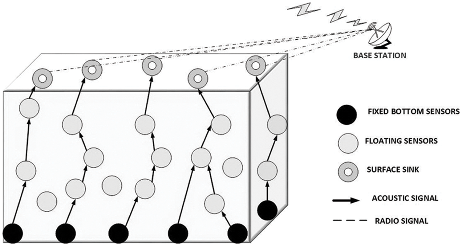
Figure 1: Architectural model of USNs
The sensor nodes are well organized in a network structure for data transmission. The categories of communication are as follows:
• Bottom mounted sensors to bottom mounted relay or forwarder
• Mobile sensors to mobile forwarder nodes
• Mobile forwarder sensor nodes to mobile sink nodes
• Sink forwards data to base station.
The control or base station receives data and processes it to get the final information.
The nodes communicate by a frequency modulation technique in ultrasonic range. The nodes for communication broadcast a HELLO message consisting of node ID, energy contained and distance. The neighbor nodes within the communication range send ACK as response to the sender’s message. The collision during ACK sending can be avoided by adjusting range of frequency of signal send by the nodes, thereby avoiding collision. In our scenario we take one sink node and seven floating nodes which communicate and finally the fittest sends to the sink, deployed in 3D space.
• Assume, node Si as a frequency value less than that of Sz. All nodes have ultrasonic receptive capability and send a reply message on receiving the HELLO message.
• At first
• In Fig. 2, Su is the nearest to Si and within its communication range. The level of Su is less than that of Si so it will not receive HELLO message, as only nodes higher than the level of sender receives the broadcast. As our objective is forward movement or routing to reach the sink.
• Sq, is the next nearest to the sender node. It sends reply with ACK message; but it is also within the transmission range of Sz. Here, a comparison is done between the intensity of message send by
• Sr, receives the message of Si and sends a ACK reply message. Also Sj after receiving the message send ACK to the sender as well as other nodes within the radius Sj. Assuming, the residual energy of Sj is much more than other receptors. So, Sj is chosen to communicate with Si as it is the fittest.
• Similarly, Sz broadcast a HELLO message on hearing Si sends ACK with higher intensity. This call is received by Sp and Sq which are in its communication range. Both send the reply ACK message with their location and residual energy information.
• Assume that Sp is selected as the fittest as it has more residual energy Sq. So, the two efficient receptors are found to be Sj for Si and Sp for Sz. Lastly Sj is to be selected as it is nearer to the sink node
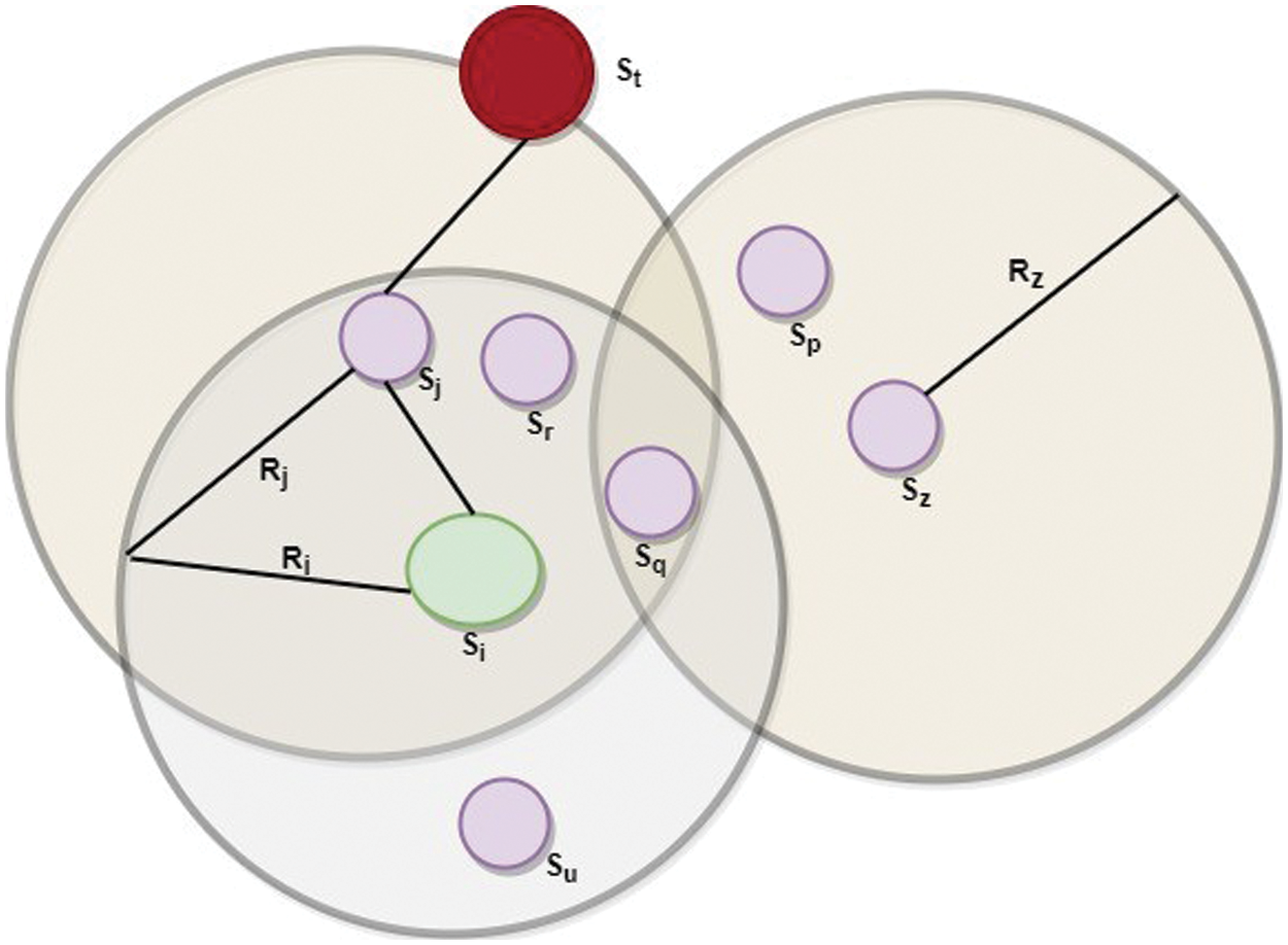
Figure 2: Packet transmission architecture
In this phase, energy consumption is minimized by mechanism of efficient next hop selection and computation of RE with DATA/ACK mechanism compared to E2LR and DEEP.
Our proposed protocol basically consists of two stages:
• Forwarder or candidate node election phase.
• Forwarder node selection phase.
The sensor nodes along with their Residual Energy (RE) are taken into consideration. The sink node conserves its energy by equipment of both radiofrequency (RF) and acoustic modems. It uses the RF modem to communicate with the onshore data station and the acoustic modem to communicate with the underwater sensors. The sink periodically broadcast message that contains information about its location. The sensor nodes that hold the data packet are the transmitter and the nodes receiving are receptors. Every data transmitted or retransmitted from the receptor as reply message. The reply contains in its header the location source node, forwarder node, sink node and RE of each node. ri is taken as rmin is the transmission range.
where, rmin -radius of Si i.e., ri;
In best case analysis when the residual energy of the node is not at all exhausted rmax ≥ 2rmin and
where, i–transmitter; j-its upper neighbor
Calculation of link quality, fitness factor and energy as per [6], to calculate the delivery efficiency based on the three factors by selecting the optimal forwarder node.
RPt is the number of received packet in time t, EPt is the number of expected packet in time t.
Ei,j(T) is the total Energy consumption.
D Ei,j(T) is the delivery efficiency factor.
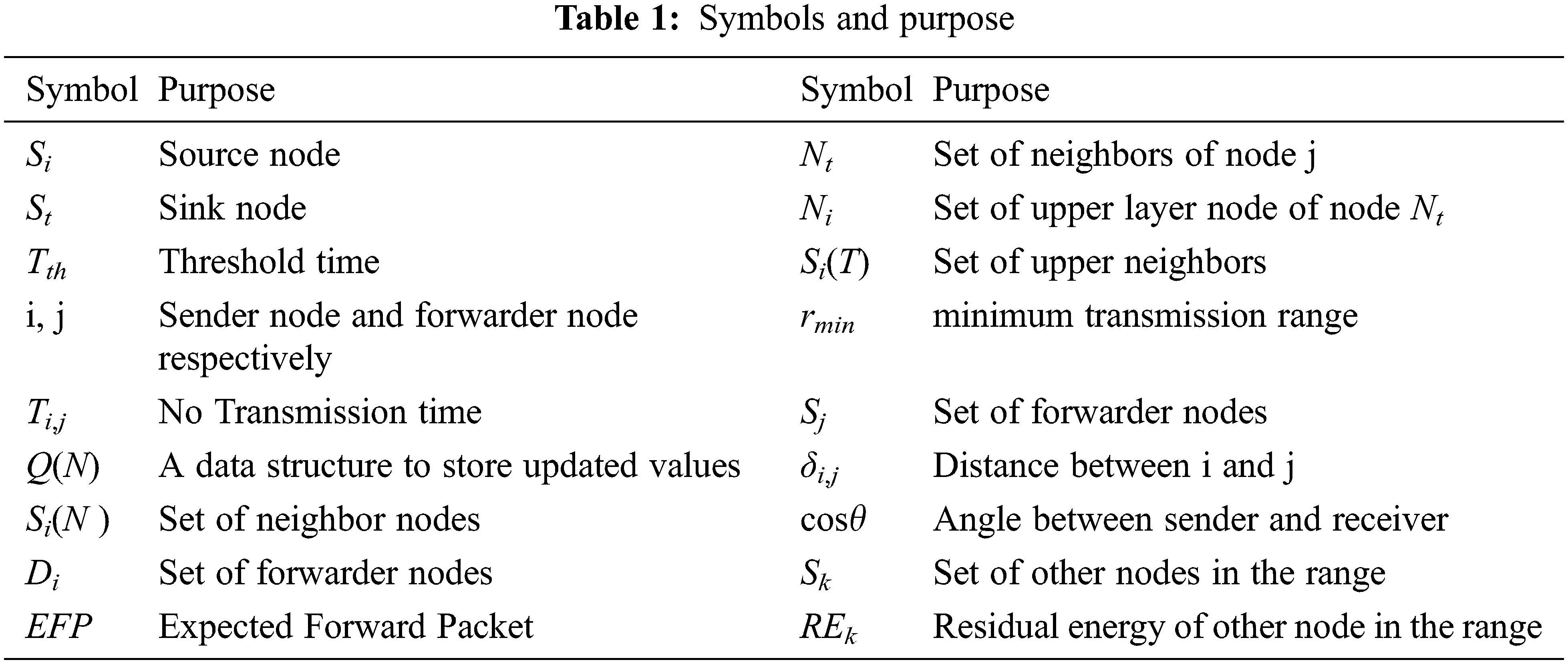
The symbols used in Algorithm 1 and Algorithm 2 are presented, and the purpose is defined in Tab. 1.
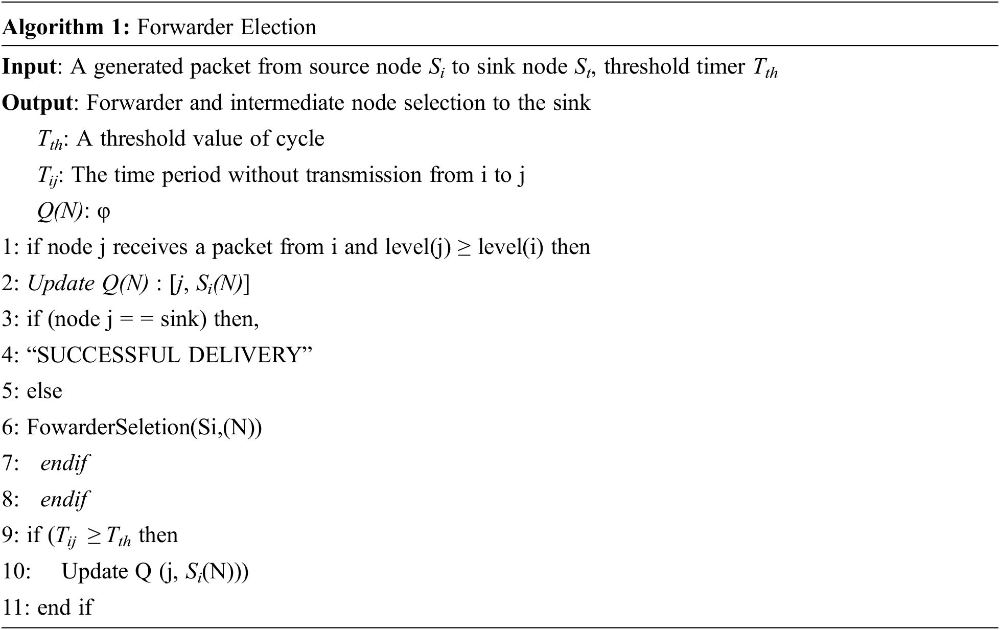
The algorithm 1 describes how the packet is transmitted to the sink by repeatedly selecting a forwarder as per the algorithm 2 till it reaches the sink or the transmission fails. Each node contains the information of their neighbor. If there is a period of no transmission, the information is updated. A timer is set at each node and a threshold is taken for minimization of energy consumption and latency due to waiting time. The packets are received only if the sender is present at the lower level if not it discards the packet. Only a selective set of nodes are selected to be forwarder thereby minimizing delay and improving packet delivery ratio.
The forwarding selection process from neighbors is demonstrated in this section with the help of an algorithm. All the prerequisite information is collected before transmission. The sender will select the forwarder nodes based on the value of DE. This procedure continues till there is no forwarder node available and thus the process comes to a halt. In forwarder selection algorithm, Si(N) in step 1 is the set of upper layer nodes which is stored in Di(S) which contains the set of forwarder nodes of i (sender). Ni is the upper layer node of Nt and threshold timer Tth in step 4, is set to be greater than 0. If no upper layer node is present than null value is assigned to the set of upper neighbor Si(T). Then values of cos θ in step 8, is calculated based on the angular distance between nodes. If this value is found to be less than 0 then the receiver node goes to sleep mode else it is added to the set of forwarder node. This receiver node transmits a reply message in its transmission range so as to avoid colliding. Again, if the residual energy of any node compared with the other receiver nodes; the node having less residual energy goes to sleep mode. It helps the node to preserve its energy so that it can be selected as the forwarder node in the next iteration process. Thus, we conclude that a node present in the upper layer of the sender and having residual energy more than other receiver nodes is selected as the forwarder node.
In Algorithm 2, an Expected Forward Packet (EFP) value in step 29, is taken that depends on the link quality. Its value should be larger than a defined value of lower bound of EFP to increase the packet delivery ratio. The algorithm checks whether or not the forwarder node is the sink, if it finds the sink the iteration stops else it checks for the eligible forwarder node based on residual energy (RE) and delivery efficiency (DE). A maximum transmission range rmax is set so that the distance between the sender and forwarder δi,j in step 7, is within this value. PO is the initial transmit power, x is the ratio between distance and energy consumption [15] used for calculating the total energy consumption in transmission of packet from node i to j. If a node has angle of cos θ between source to forwarder and forwarder to sink less than 0 then it goes to sleep mode else added to Si(T) from steps 15–19. If the RE of any other node is found to be higher than the RE of the forwarder, then that node is next added to set of forwarder Si(T). The delivery efficiency factor is calculated based on the link quality value LQi,j , the fitness factor Fi,j and the energy consumption Ei,j from steps 23–26 as in [15]. The forwarder node is finally selected based on better delivery efficiency factor DEi,j and maximum residual energy content. The link qualities of selected forwarder are continuously added to the EFP value. The calculation of DE looks for better candidate node to be selected as the forwarder thus, minimizing energy efficiency and improving packet delivery ratio.
Collision depends on path loss, fading effect and mostly on the noise factor. We, initially compute the SNR factor by considering various factors. Path loss calculation is done by Urick’s [16] formula,
A0 - Normalizing factor which a constant term
k - spreading factor (taken to be 1.5); d – distance; f - frequency
α(f) - sound wave absorption loss measured in dB/km given by Thorp’s formula in [16]
In underwater there are four types of noise those are turbulence, shipping waves, wind velocity, and thermal noise computed in Eqs. (10)–(13) respectively. This can be expressed by continuous power spectral density (p.s.d) and Gaussian Statistics as illustrated in equations below.
s is the shipping activity factor lies between 0 to 1, w is the wind speed meter per second.
Thus, resulting a resultant p.s.d of ambient noise NL in underwater is given by Eq. (7).
SNR can be calculated as:
DI (Directive Index) is the directive factor, here assumed to be 0, considering omnidirectional antennas.
SL (Source Level) - intensity of sound radiated (measured in decibels related to intensity of a plane wave of root mean square (rms) pressure of 1μPa equal to 1 yard (0.9144 m) from “acoustic center” of the source to the destination).
Pi - transmission power of initial sender; Pj - transmission power of interfering sender.
B - bandwidth for communication frequency f.
A0 - a constant factor [17].
K - spreading factor (taken to be 1.5 in UWSNs).
d - distance between the sender and receiver
α - absorption co-efficiency [18].
There is N + 1 number of nodes. The source node is taken as S0 and the sink is Sn the number of intermediate nodes is N − 1. The Bit Error Rate (BER) is calculated using Eq. (17) [19]:
This is considered as per (Adaptive White Gaussian Noise) AWGN channel assuming (Bi- nary Phase Shift Keying) BFSK modulation using Gaussian function.
Eb − energy consumed per bit
N0 − noise power spectral density.
The interference range is defined as a distance to a receiver that, if some nodes send packet within this distance, will cause collision to an on-going reception of the receiver. A higher value of SINR gives better BER and if the ratio between wanted and unwanted signal decreases; it is very difficult to find the error bit.
For avoiding collision our focus is laid on SINR (Signal Interference Noise Ratio) calculation, unlike SNR in E2LR and DEEP. The SINR value can also be adjusted dynamically by adjusting the power of sender. According to computation of propagation distance, signal frequency, ambient noise factor. Thus, SINR computation provides collision avoidance and prolonged network lifetime. By applying the SINR calculation collision avoidance phase, we observed that collision is noticeably avoided. As, the Forwarder(relay) node selection based on SINR value is not very effective, we have incorporated the RE concept to overcome performance degradation, even when the distance between transmitter and receiver increases. By this mechanism we can predict that FSE2R forwarder node selection is much more reliable than that of compared protocols E2LR and DEEP.
Primarily, the performance of a network can be evaluated by energy consumption and throughput calculations. The energy consumption in underwater is major factor involving propagation delay, bandwidth, distance, path loss. So, calculation of energy consumption also includes all these factors. An energy calculation model based on concept of Residual energy Levels (RLs) is proposed in [20].
The initial energy E0 is divided into energy levels. Thus, the URL (Unit Energy Level) is calculated as:
L is the optimum number of RLs.
The total energy consumption of a node can be determined by:
So,
In the initial stage of data transmission process REs (residual energies) of all nodes are same. While transmission to the next hop by multi-hop method the residual energies of node j and k are calculated as Eqs. (22) and (23).
β is equal to URL value as the nodes transmits in there transmitting range and,
From Eqs. (21)–(24), it proves that nodes with minimum distance to sink consume more energy for relaying data packets. If
d - distance between sender and receiver; k - spreading factor; α - absorption coefficient described earlier
P0 - initial transmit power; Rmax maximum transmission range; L - length of packet and t is the transmission time.
As the energy consumption mostly depends on the distance-bandwidth and distance between transmission nodes, energy calculation is based on these factors as per [12], where bandwidth is taken to be 3 dB. Thus, the energy consumption is calculated as given in Eq. (26).
Throughput of the network is calculated as:
n - total number of data packets; Pl - length of each packet; t - total time taken for successful transmission of n packets.
The performance evaluation of FSE2R is presented in this section compared to other protocols H2DAB, DEEP, E2LR. NS3 with features of underwater network scenario and acoustic channel is used for simulation. This section has a detailed description of simulation parameters, environment scenario considered, and performance metrics used for protocol evaluation.
The NS3 simulation tool is widely used in 3D environment and discrete event-driven simulations, having predefined collision models, MAC protocols, routing protocols. NS3 has various predefined classes that is an aid to our simulation and model implementation with ease. A 3D sensor network environment is set up of 2000 × 3000 × 5000 m3 and deployment of nodes are done randomly. Total deployed nodes are about 100 to 600 with a transmission range of 1500 m. There are five floating sink nodes in the surface of water. The turn on power value is taken to be 10 W, the receiving power to be 5 W. The propagation model used for simulation is Two-Ray Ground with total simulation time of 3000 s. The nodes are moving at speed of 0 to 3 m/s. By applying the SINR calculation in underwater MAC protocol collision is avoided. The incorporation of RE minimizes the energy consumption. Some of the nodes are source nodes for data generation and other are the relay nodes for transmission and forwarding. The performance of our proposal FSE2R, found better in all the observed cases demonstrated in Section 5.3.
Our proposal considers location and distance between nodes to be known. The next transmitting nodes are selected depending upon RE which helps in minimizing the energy consumption to a large extent. The DE calculated based on link quality, energy consumed and distance so as to select an efficient forwarder node. H2DAB is distributed underwater localization-based protocol where data is forwarded by selecting next-hop, there is no consideration of energy factor which may lead to dead nodes causing communication failure. E2LR manages flooding to minimize the energy consumption and estimates the link quality for reliable transmission. DEEP on other hand computes a DE factor based on link quality, node distance and energy factor but still there is no computation of residual energy for managing consumed energy. Therefore, in proposed protocol we have incorporated an effective DE computation, RE computation along with SINR computation; these calculations enable to achieve a better energy efficiency with collision avoidance. Thereby, improvising the packet delivery, energy consumption and end-to-end delay compared to H2DAB, DEEP and E2LR in accordance with speed of nodes as well as number of nodes.
Network Evaluation depends upon the performance metrics, the metrics are as follows:
End-to-End delay: It is the required time taken by a node to transmit a message from source to destination across a network [21].
Packet Delivery Ratio: It is the ratio of successful packet delivered to the total packet sent. It must be kept high in a network by limiting the traffic. If PDR is high throughput will also suffer, thus they are directly proportional [22,23].
Energy Consumption: Amount of energy needed to provide efficient services to the environment. Energy consumption should be minimum so as to save the network lifetime.
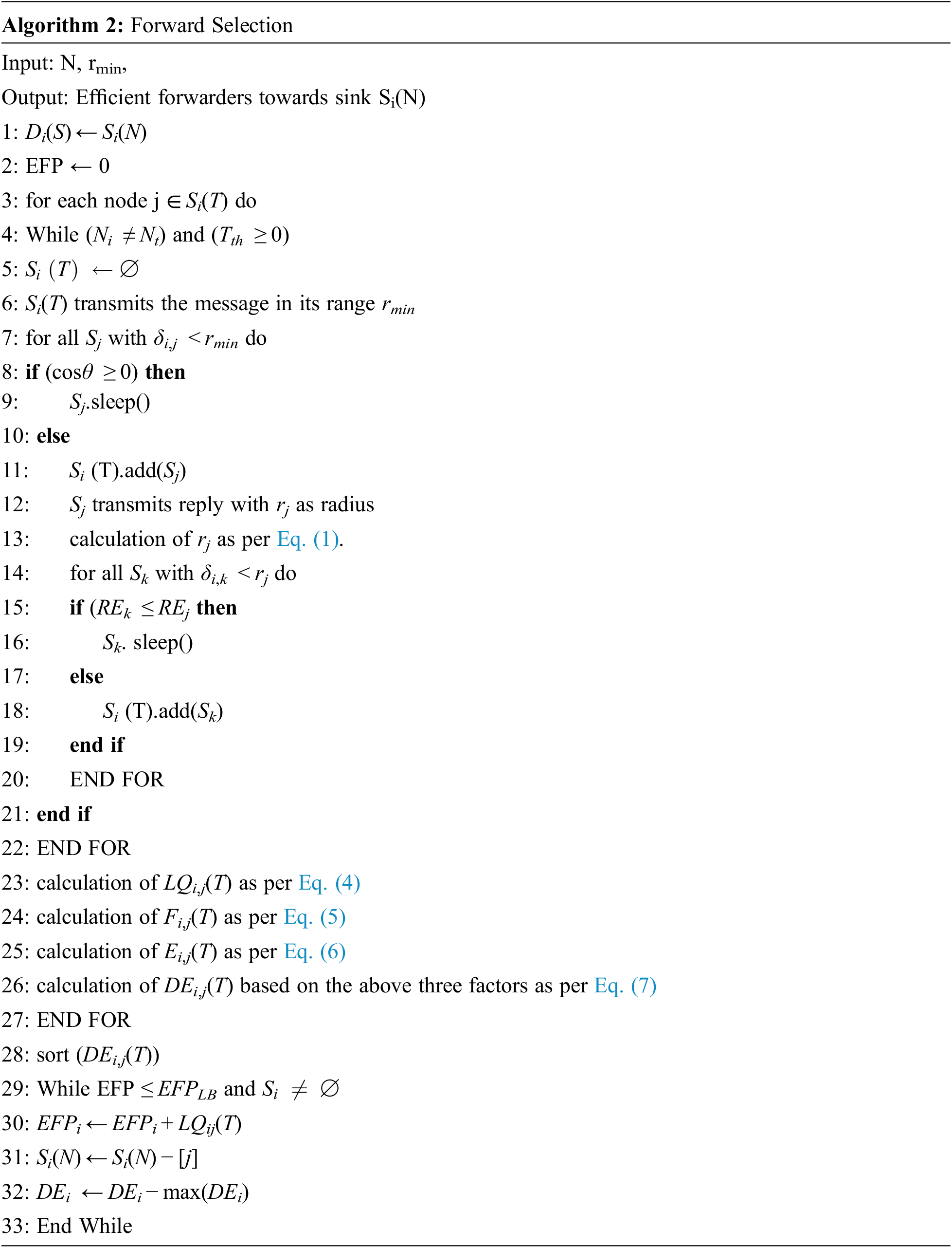
In Figs. 3 and 4, it is depicted that the energy consumption of FSE2R is less than the other compared protocol during data transmission. Comparative analysis presents that FSE2R shows 70% better than H2DAB, 15.3% and 11.7% better than DEEP and E2LR respectively on increasing number of nodes. Similarly, on increasing the speed of node FSE2R performs 65% better than H2DAB, 8.98% and 5.68% better than DEEP and E2LR respectively. The incorporation of concept of residual energy, which is not present in any of the compared protocols, contributes for less energy consumption. The residual energy is used to minimize the consumption of node’s battery to prolong the network lifetime thereby minimizing the energy consumed. By the concept of RE, we choose the nodes having more RE as the forwarder, thereby saving the energy of nodes having less RE. Further the collision avoidance mechanism of FSE2R is more efficient than compared protocols achieved by computation of SINR in MAC. The inclusion of residual energy, SINR calculations for packet delivery and keeping time to time track on the location of nodes helps to choose a better forwarder node to minimize the energy consumption.
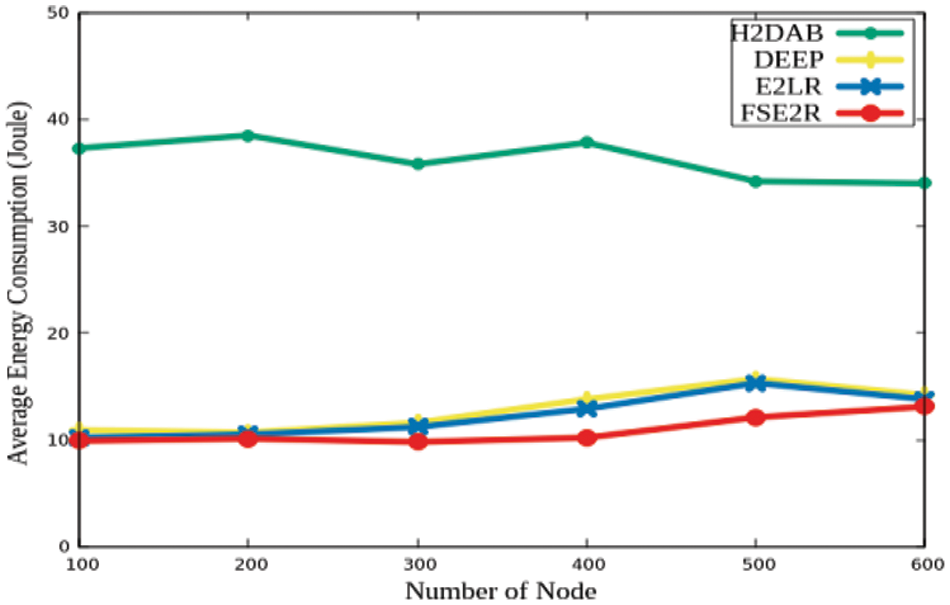
Figure 3: Number of nodes vs. Average energy consumption
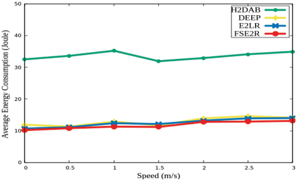
Figure 4: Speed vs. Average energy consumption
5.4.2 Packet Delivery Ratio (PDR)
PDR as shown in Fig. 5, is better in proposed protocol as compared to H2AB, DEEP, and E2LR, even in less density area. The PDR vs. speed of node is depicted in Fig. 6, and it is observed that each protocol has significant effects on packet delivery ratio. Proposed protocol performs better than other protocols even in high mobility node environment. The PDR in case of our proposal outperforms other protocols even with the increasing speed of nodes. For instance, FSE2R shows 63% better result in terms of PDR than H2DAB, 23.1% and 10.4% better than DEEP and E2LR respectively with varying number of nodes. The model shows 31.5% better result than H2DAB, 11.90% and 7.84% better than DEEP and E2LR respectively in terms of varying speed of node. In FSE2R, the calculation of delivery efficiency factor in Eq. (18) which increases the probability of successful delivery to the receptor contributes for better PDR. As the proposed protocol considers computation of link quality, distance, routing packet via reliable link the PDR is maximized. The forwarder is selected based on high value of DE, this states the forwarder node is having a better link quality and nearer to the receptor, thereby improving the PDR. The FSE2R successfully delivers most of its packets by selecting the best hop by taking into consideration link quality, and reliable forwarder node, thereby minimizing redundant packet delivery via efficient link to next hop.
Figure 5: Number of nodes vs. Packet delivery ratio
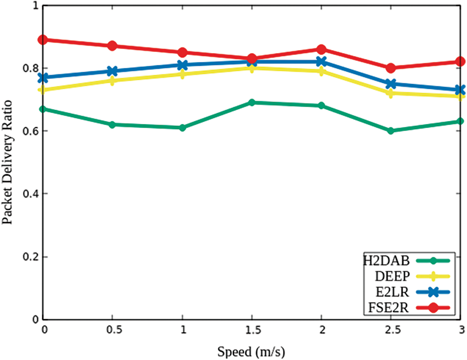
Figure 6: Speed vs. Packet delivery ratio
Fig. 7 reveals that delay of other compared algorithms is greater than our proposed protocol. So, proposed protocol has faster data processing time due to collision avoidance. The end-to-end delay is mostly affected in high mobile region with increase of speed. The mobility of node improves the communication between them thereby improving the packet processing time and minimizing delay. As per the simulation result it shows that our protocol outperforms other protocols with respect speed of nodes vs. end to end delay as depicted in Fig. 8. The delay of FSE2R is 68.4% better than H2DAB, 37.79% and 27.86% better than DEEP and E2LR varying node number. Whereas 72.03% better than H2DAB, 42.19% and 41.69% better than DEEP and E2LR respectively varying node mobility. For time constraint applications like underwater there is strict time requirement therefore, end-to-end-delay plays a significant role. As the number of nodes increases like for a dense scenario the end-to-end delay increase. End-to-End Delay grows with the network diversity, which is calculated by the time interval, starting from the initial packet that reached the destination successfully. The proposed algorithm shows less end-to-end delay due to effective packet transmission through the forwarder node and collision avoidance. FSE2R implementation is based on efficient MAC layer design by use of collision avoidance scheme thereby providing less delay. As the collision is minimized the nodes need not wait for long before packet transmission as they will sense the channel free for next transmission.
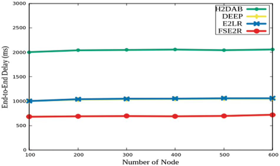
Figure 7: Number of nodes vs. End-to-End Delay
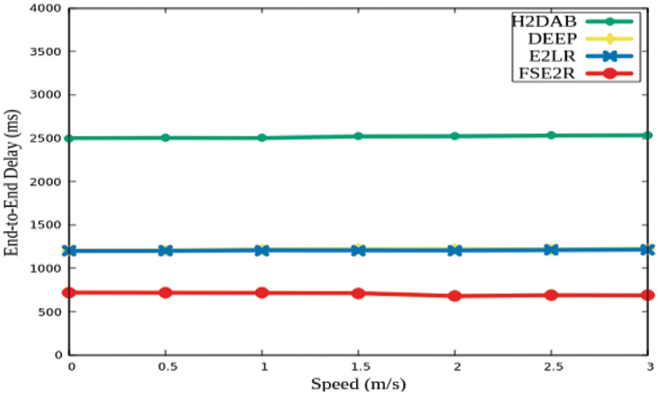
Figure 8: Speed vs. End-to-End Delay
The design of an efficient routing algorithm is a vital necessity of underwater network scenario, due to heavy network overhead with external factors like depth and pressure of water. The proposed protocol considers energy consumption, packet delivery ratio and end-to-end delay parameters for evaluation. Starting from a detailed description about proposed protocol FSE2R computes residual energy, delivery efficiency and SINR. FSE2R is compared with existing protocols like H2DAB, DEEP and E2LR. FSEER computes delivery efficiency factor based on distance of node, link quality and energy as described in Section 3.3. The incorporation of residual energy provides reduced energy consumption, computation of DE for efficient forwarding provides better packet delivery, whereas the computation of SINR aid in collision avoidance thereby minimizing delay. Simulation result shows that our proposal outperforms compared protocols in terms of energy efficiency, latency and PDR with variation of speed as well as number of nodes. Thus, our protocol can to some extent overcome the constraints of underwater scenario thereby providing reliability and efficiency in data transmission. The proposed proposal is designed to minimize energy consumption. But challenges persist in terms of channel and bandwidth utilization due to the adverse environment. Most researchers are facing challenges in designing an efficient MAC and routing layer protocols. With the upcoming technologies such as 5G/6G and SDN communication reliability and link utilization can be improved with minimized latency and high throughput.
Funding Statement: The authors would like to thank for the support from Taif University Researchers Supporting Project number (TURSP-2020/10), Taif University, Taif, Saudi Arabia.
Conflicts of Interest: The authors declare that they have no conflicts of interest to report regarding the present study
1. H. Gul, G. Ullah, M. Khan and Y. Khan, “EERBCR: Energy-efficient regional based cooperative routing protocol for underwater sensor networks with sink mobility,” Journal of Ambient Intelligence and Humanized Computing, Springer, 2021, pp. 1–13, 2021. [Google Scholar]
2. K. F. Haque, K. H. Kabir and A. Abdelgawad, “Advancement of routing protocols and applications of underwater wireless sensor network (UWSN)—A survey,” Journal of Sensor and Actuator Networks, vol. 9, no. 2, pp. 19, 2020. [Google Scholar]
3. R. W. L. Coutinho, A. Boukerche, L. F. M. Vieira and A. A. F. Loureiro, “Underwater sensor networks for smart disaster management,” IEEE Consumer Electronics Magazine, vol. 9, no. 2, pp. 107–114, 2020. [Google Scholar]
4. M. C. Domingo and R. Prior, “A distributed clustering scheme for underwater wireless sensor networks,” in 2007 IEEE 18th Int. Symposium on Personal, Indoor and Mobile Radio Communications, Athens, Greece, pp. 1–5. 2007. [Google Scholar]
5. K. G. Winstonm, T. Seah and X. Hwee, “Multipath virtual sink architecture for underwater sensor networks,” IEEE Oceans, 2006, pp. 1–6, 2006. [Google Scholar]
6. K. M. Awan, P. A. Shah, K. Iqbal, S. Gillani, W. Ahmad et al., “Underwater wireless sensor networks: A review of recent issues and challenges,” Wireless Communications and Mobile Computing, vol. 2019, Article ID 6470359, 2019. [Google Scholar]
7. P. Xie, J. H. Cui and L. Lao, “VBF: Vector-based forwarding protocol for underwater sensor networks,” in: Proceedings of the 5th Int. IFIP-TC6 Networking Conf., Networking, Coimbra, Portugal, pp. 1216–1221, 2016. [Google Scholar]
8. N. Nicolaou, A. See, P. Xie, J. Cui and D. Maggiorini, “Improving the robustness of location-based routing for underwater sensor networks,” in OCEANS, 2007, Europe, IEEE, pp. 1–6, 2007. [Google Scholar]
9. J. M. Jornet, M. Stojanovic and M. Zorzi, “Focused beam routing protocol for underwater acoustic networks,” Workshop on Underwater Networks, 2008, pp. 75–82, 2008. [Google Scholar]
10. H. Yan, Z. J. Shi and J. H. Cui, “DBR: Depth-based routing for underwater sensor networks,” in Proc. of the 7th Int. IFIP-TC6 Networking Conf. on Adhoc and Sensor Networks, Wireless Networks, Next Generation Internet, Singapore, pp. 72–86, 2008. [Google Scholar]
11. Y. Noh, U. Li, S. Lee, P. Wang, L. F. Vieira et al., “HydroCast: Pressure routing for underwater sensor networks,” IEEE Transactions on Vehicular Technology, vol. 65, no. 1, pp. 333–347, 2016. [Google Scholar]
12. C. H. Yang, K. F. Ssu and C. L. Yang, “A Collision-analysis-based energy efficient routing protocol in 3D underwater acoustic sensor networks,” Elsevier, vol. 66, pp. 25–35, 2015. [Google Scholar]
13. A. Wahid, S. Lee and D. Kim, “A reliable and energy-efficient routing protocol for underwater wireless sensor networks,” International Journal of Communication System, vol. 27, no. 10, pp. 2048–2062, 2014. [Google Scholar]
14. M. Ayaz and A. Abdullah, “Hop-by-hop dynamic addressing based (H2- DAB) routing protocol for underwater wireless sensor networks,” in Proc. of the Int. 20 Conf. on Information and Multimedia Technology, ICIMT’ 09, Republic of Korea, pp. 436–441, 2009. [Google Scholar]
15. M. Tariq, M. Ayaz, F. Subhan and M. Z. Abbas, “Energy efficient and link reliable routing (E2LR) scheme for underwater sensor networks,” Springer Nature, vol. 14, pp. 1870–1888, 2021. [Google Scholar]
16. L. M. Brekhovskikh and Y. Lysanov, “Fundamentals of Ocean Acoustics,” Springer-Verlag, New York, AIP Press/Springer, vol. 21, 2003. [Google Scholar]
17. Y. Su, Y. Zhu, H. Mo, J. H. Cui and Z. Jin, “A joint power control and rate adaptation MAC protocol for underwater sensor networks,” Ad Hoc Networks, vol. 26, pp. 36–49, 2015. [Google Scholar]
18. A. Goldsmith, “Wireless Communication,” United States of America by Cambridge University Press, New York, 2005. [Google Scholar]
19. M. Stojanovic, “On the relationship between capacity and distance in an underwater acoustic channel,” ACM SIGMOBILE Mobile Computing and Communication Reviews, vol. 11, no. 4, pp. 34–43, 2007. [Google Scholar]
20. N. Javaid, M. Shah, A. Ahmad, M. Imran, M. I. Khan et al., “An enhanced energy balanced data transmission protocol for underwater acoustic sensor networks,” Sensors, MDPI, vol. 16, No. no. 4, pp. 487, 2016. [Google Scholar]
21. R. P. Nayak, S. Sethi, S. K. Bhoi, K. S. Sahoo, N. Z. Jhanjhi et al., “TBDDoSA-MD: Trust-based DDoS misbehave detection approach in software-defined vehicular network (SDVN),” Computers, Materials & Continua, vol. 69, no. 3, pp. 3513–3529, 2021. [Google Scholar]
22. S. K. Mishra, S. Mishra, A. Alsayat, N. Z. Jhanjhi, M. Humayun et al., “Energy-aware task allocation for multi-cloud networks,” IEEE Access, vol. 8, pp. 178825–178834, 2020. [Google Scholar]
23. S. Rout, K. S. Sahoo, S. S. Patra, B. Sahoo and D. Puthal, “Energy efficiency in software defined networking: A survey,” SN Computer Science, vol. 2, no. 4, pp. 1–15, 2021. [Google Scholar]
 | This work is licensed under a Creative Commons Attribution 4.0 International License, which permits unrestricted use, distribution, and reproduction in any medium, provided the original work is properly cited. |