DOI:10.32604/EE.2020.011237
| Energy Engineering DOI:10.32604/EE.2020.011237 | |
| Article |
Lattice Boltzmann Simulation of Magnetic Field Effect on Electrically Conducting Fluid at Inclined Angles in Rayleigh-Bénard Convection
1Department of Mathematics and Physics, North South University, Dhaka, 1229, Bangladesh
2Center for Applied Scientific Computing (CASC), North South University, Dhaka, 1229, Bangladesh
3Department of Engineering & Physical Sciences, La Trobe University, Melbourne, VIC 3086, Australia
4Department of Mathematics, Dhaka University of Science and Technology, Gazipur, Bangladesh
5School of Mechanical and Mechatronic Engineering, University of Technology Sydney, Ultimo, Australia
*Corresponding Author: M. M. Molla. Email: mamun.molla@northsouth.edu
Received: 29 April 2020; Accepted: 11 August 2020
Abstract: The magneto-hydrodynamics (MHD) effect is studied at different inclined angles in Rayleigh-Bénard (RB) convection inside a rectangular enclosure using the lattice Boltzmann method (LBM). The enclosure is filled with electrically conducting fluids of different characteristics. These characteristics are defined by Prandtl number, Pr. The considered Pr values for this study are 10 and 70. The influence of other dimensionless parameters Rayleigh numbers  and Hartmann numbers Ha = 0, 10, 25, 50, 100, on fluid flow and heat transfer, are also investigated considering different inclined angles φ of magnetic field by analyzing computed local Nusselt numbers and average Nusselt numbers. The results of the study show the undoubted prediction capability of LBM for the current problem. The simulated results demonstrate that the augmentation in heat transfer is directly related to Ra values, but it is opposite while observing the characteristics of Ha values. However, it is also found that φ has a significant impact on heat transfer for different fluids. Besides, isotherms are found to be always parallel to the horizontal axis at
  as conduction overcomes the convection in the heat transfer, but this behaviour is not seen at
  when
when  . Furthermore, at
  , oscillatory instability appears but LBM is still able to provide a complete map of this predicted behavior. An appropriate validation with previous numerical studies demonstrates the accuracy of the present approach.
Keywords: Average rate of heat transfer; Hartmann number; lattice Boltzmann method; magnetic field effect; Rayleigh-Bernard convection
The research of buoyancy-driven fluid motion is pivotal to different areas of the scientific community from numerous applications of heat transfer and non-linear dynamics to geology and hydrology. Particularly, in heat transfer, natural convection is extensively studied due to its widespread phenomena, and well-interpreted pathways to expand for further applications like fluid phase transition, boiling, and, evaporation processes in solar and cooling ponds, metal casting, galvanising, to name a few. To satisfy those requirements, certain natural convection problems have been taken into account to observe several non-linear dynamics fields related behaviours such as pattern forming system, bifurcation structure in different temperature gradients and cavity configurations [1]. Although there are several theories to explain those configurations in fluids, the Rayleigh-Benard (RB) convection is a popular paradigm of those types of studies [1–6]. RB convection is defined as a special type of cell where fluids are heated from the bottom surface and cooled on the top surface, and the flow in between is driven by buoyancy force due to the difference in the density. It is also able to transform itself into thermal convection when the temperature gradient surpasses a certain threshold level [7]. The theoretical aspect of RB convection, which was initiated in 1916 by Lord Rayleigh, can answer a large number of queries on temperature gradient convection for many years.
In computational fluid dynamics (CFD) investigations, numerical simulations are attributed to providing adequate information which is useful in several ways, since the experimental programmes are quite expensive and relatively cumbersome [8]. While some popular numerical techniques such as finite difference [9], finite element [10–12], finite volume [13,14] have served the researchers for decades, the Lattice Boltzmann Method (LBM) is gaining popularity in the modern era due to its versatility, efficiency and reproducibility [3,15–18]. Furthermore, in LBM, since fluid motion is simulated at the distribution functions level, the microscopic physics of fluid particles can be incorporated competently like the other conventional methods [8]. However, LBM is considered to be successful for implementing mass and momentum conservation only, where the macroscopic equations correspond to the Navier-Stokes equation with an ideal gas equation state and a constant temperature. On the other hand, LBM has not achieved the same accolade yet in the simulation of thermal systems or hybrid thermal systems like variation of isothermal flows in magneto-hydrodynamic (MHD) [2,19]. The flow of an electrically conducting fluid in a magnetic field is vastly influenced by MHD forces, due to the interaction of induced electric currents with the applied magnetic field. One of the vital reasons for considering electromagnetic effect is to stabilise the fluid flow and subdue oscillatory instabilities. Although the MHD in natural convection has gained attention among researchers to some extent, most of them raised concerns regarding LBM’s failure to secure the numerical stability for temperature individually, particularly in the three-dimensional analysis [8]. One of the reasons is the existence of the inter-particle forces, which are included in most of the multi-phase models. As a consequence, the conservation of the thermal energy, in general, experiences resistance from the potential part of the internal energy. Therefore, simulating fluid like a non-ideal gas with energy conservation is difficult to obtain. Besides, there are certain circumstances where the viscous and compressive heating effects can be ignored, and the temperature field will be inertly advected by the fluid flow. By considering this characteristic, the diffusion of individual component in a fluid mixture can be inferred. Therefore, in one way or another, it is possible to study the isothermal flows by adding component (such as force term) in the system. There had been several research works which involved the inclusion of one or two additional components with LBM to simulate an MHD flow, and it was found to be effective for computational efficiency (both memory-wise and time-wise) [8]. Since LBM can generate contours within a short time-scale, the quality and quantity of the data are not compromised [19,5]. The accuracy of LBM-MHD flows has been widely acknowledged by several benchmark studies [20,21]. Furthermore, the orientation of the magnetic field influences the development of a convective heat and mass transfer rule, where Alchaar et al. [22] showed the impact of the magnetic field being superior in vertical direction  than horizontal direction (
 ). Hence, the role of inclined angles shouldn’t be unnoticed.
There had been several research works which involved the inclusion of one or two additional components with LBM to simulate an MHD flow, and it was found to be effective for computational efficiency (both memory-wise and time-wise) [8]. Since LBM can generate contours within a short time-scale, the quality and quantity of the data are not compromised [19,5]. The accuracy of LBM-MHD flows has been widely acknowledged by several benchmark studies [20,21]. Furthermore, the orientation of the magnetic field influences the development of a convective heat and mass transfer rule, where Alchaar et al. [20] showed the impact of the magnetic field being superior in vertical direction  than horizontal direction (
 ) [22]. Hence, the role of inclined angles shouldn’t be unnoticed. The investigations regarding MHD-LBM in RB convection available in the literature are quite limited in number. To the authors’ knowledge, there has not been any specific research reported in the literature which had comprehensively studied the MHD flow at different Pr, Ha, and Ra numbers in RB convection using LBM at different inclined angles. Therefore, the novelty of the present research is to underline the impact of the aforementioned parametric importance in MHD-LBM numerical simulations. The available literatures in this relevant field miss out at least one of the parameters. Therefore, further investigation on the MHD-LBM simulation through electrically conducting fluid is still needed. The primary purpose of the present research is to establish the ability of LBM to solve MHD flow in RB convection in the presence of magnetic field changes. The methodology of the solution is presented inside an enclosed rectangular cavity after conducting four types of code validations, and after the compulsory grid-independent test. The results of LBM have been validated with benchmark solutions and they are found to be in excellent agreement.
MHD flows can be simulated in two different ways namely, the multi-speed (MS) model, and the multi-distribution function (MDF) model [15]. In the MS model, the equilibrium distribution is altered to include the magnetic field force in such a way that it becomes equal to the magnetic field vector on a separate base of the vector. Since the primary focus of this research is on the MDF model, the details on the MS model is not widely discussed in this work. The MDF model, which was introduced and further improved by Dellar [23], considers the Lorentz force to be a point-wise force, and the conventional induction equation is solved by using Lattice Bhatnagar Gross Krook (LBGK) equation by including an independent distribution function. The advantage of this technique lies in the interactions between the electrically conducting fluid and magnetic field. When both of them are in contact, the Lorentz force becomes active and interacts with the buoyancy force in governing both fluid flow and temperature fields. Since the involvement of the external magnetic field plays a vital role in the MDF model, the MHD flows require research from a broader perspective. Some of the notable points can be mentioned here, which might help the study in this field:
•Grid-independent study (different grid size)
•Investigation at different Ra numbers to see changes in the pattern of the buoyancy-driven flow,
•Variation of Pr to check the suitability of any numerical model for fluids of various characteristics,
•Influence on the flow under different magnetic field strengths (different Ha numbers),
•Reporting the impact of inclined angles ( ) on numerical values.
Considering the above requirements, some of the relevant works can be analysed from the literature. Sathiyamoorthy et al. [24] considered liquid gallium (constant Pr = 0.025) to study magnetic field effect on natural convection flow in a square cavity with the uniformly heated bottom wall and side vertical walls being linearly heated, and top wall being thermally insulated. They demonstrated the significance of inclined angles on the flow and heat transfer rates inside the cavity, but the research was confined to a fixed Rayleigh number ( ). This is something of a pitfall since Ra is associated with the buoyancy-driven flow, hence one constant value of Ra to simulate liquid gallium questions the extension of the results. Therefore, it can be assumed that the authors did not put much inflexion on point (ii). However, the concerns regarding varying Ra numbers were properly addressed by Nemati et al. [25], where they reported magnetic field effects on nanofluid in a rectangular cavity, but unlike Sathiyamoorthy et al. [24], the impact of the magnetic field with inclined angle wasn’t considered. On the other hand, there is some well-constructed research which implies the significance of the aforementioned points. For example, Pirmohammadi et al. [26] studied the convective heat and mass transfer inside a tilted square closed cavity varying Ra, Ha, and
  . However, although the authors declared the grid independency confirmation, their works didn’t distinctly remark the possible mesh size and discrepancies in
 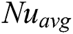 numbers. The latter issue is extensively discussed in [5], as they reported the hydrothermal behaviour of nanofluid in a cubic cavity with
  Ra
Ra  , which means the results covered a wide range of combination of simulations. Recently, Sajjadi et al. [27] reported MHD natural convection using double multi-relaxation-time (MRT) keeping Grashof number (=Ra/Pr) as variables for fixed Pr. Therefore, considering some well-cited literature, it can be stated that a proper numerical study in this area should be established considering those aforementioned points.
The geometry of the present model is plotted in Fig. 1. It shows a two-dimensional rectangular cavity with a vertical height of H and a horizontal length of L = 2H. The horizontal bottom wall is kept at a high temperature  while the top horizontal wall is maintained at a low temperature
  . The vertical left and right walls are impermeable to mass transfer (adiabatic). Pure fluid of different Prandtl numbers (Pr = 10, 70) fills the enclosure. The gravitational acceleration (
 ) is considered to be acting vertically downwards. Also, the uniform magnetic field is applied at an angle (
 = 0, 45, 90) with a constant magnitude of B between X and Y directions. In this investigation, only applied magnetic field is considered, while the induced magnetic field, produced by the flow of electrically conducting fluid is neglected. For the simplicity of the present study, Joule heating and viscous dissipation are also assumed to be negligible. To maintain the validity of the Boussinesq approximation, the density of the fluid varies. The flow inside the domain is two-dimensional, incompressible and laminar.
Figure 1: Geometry and co-ordinates of rectangular cavity configuration with magnetic field effect
4.1 The Governing Equations for MHD Natural Convection
Initially, equations for Continuity, u-Momentum, v-Momentum and the energy equations can be written as they are shown in Eqs. (1)–(4):


The following relations are implied to convert Eqs. (1)–(4) into dimensionless parameters:
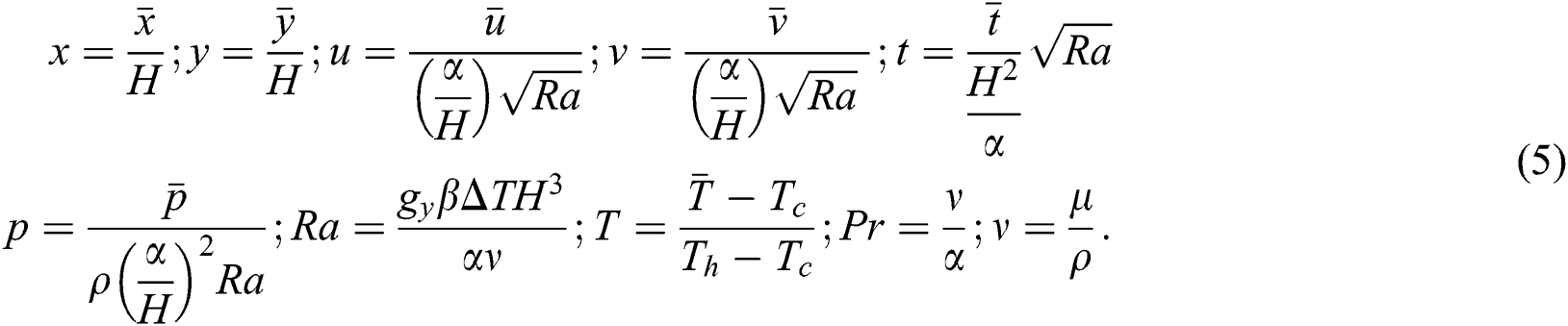
In the present investigation, the lattice Boltzmann equation is associated with the continuity Eq. (6), the momentum Eqs. (7)–(8), and the energy Eq. (9) which are derived from Eqs. (1)–(4) to simulate MHD natural convection using macroscopic variables, these are:


where  is density, u is of velocity at x-direction, v is of velocity at y-direction, T is the temperature of the fluid,
  is hot temperature,
  is cold temperature, and
  is the thermal diffusivity.
Also, Ha is Hartmann number which is defined as  ,
,  is the dynamic viscosity,
  is the electrical conductivity, B is the magnitude of the magnetic field, L is the characteristic length of the cavity,
  is the angle of the direction of the magnetic field,
  is the gravitational force acting downwards in the y-direction,
  is thermal expansion coefficient,
  is the temperature difference between the top and the bottom walls, and
  .
.
Lattice Boltzmann method (LBM) can be used to study the natural convection in pure fluid [3,28]. To implement this method, viscous heat dissipation has been neglected in incompressible flow application. There are two distribution functions in the LB model namely, the density distribution function  for flow field, and the temperature distribution function
  for temperature field. The distribution functions are defined as the probability of particles at time t in position x moving with lattice speed
  towards each lattice direction i during time interval
  . The distribution functions follow their lattice LB transport equations with single Bhatnagar-Gross-Krook (BGK) approximation. The LB equations with external forces are expressed as in the following [2,3,29–31]:


Here,  and
and  represent the single-relaxation-times that determine the rate of approach to equilibrium, and
  is the kinematic viscosity. Eqs. (6)–(8) are recovered from Eq. (10). The external term
  in Eq. (10) represents the total body forces in Eqs. (7)–(8) acting in x and y directions. The evolution of the internal energy is defined by Eq. (11) and this leads to Eq. (9).
The macroscopic quantities, that is, flow momentum, fluid density and temperature, are written as follows [32]:


The simulations in this work use the D2Q9 (two-dimensional nine-velocity) model for flow and temperature [33], as shown in Fig. 2. Therefore, the equilibrium distribution function for flow, and thermal energy distribution function for this model can be written as in the following [34]:
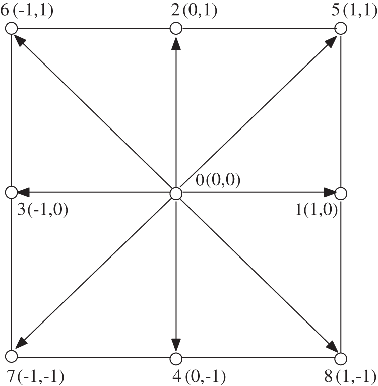
Figure 2: Discrete velocity vectors for the D2Q9 model for two-dimensional LBM


Here,  is the weighting factor (
 for i = 0; 1/9 for i = 1 to 4; 1/36 for i = 5 to 8. c is the lattice speed,
  is the speed of sound and
  is the discrete velocity vector for D2Q9 [3], and the values are
  for i = 0;
  ,
,  for i = 1 to 4;
  ,
,  for i = 5 to 8.).
4.3 Rayleigh-Benard (RB) Convection
In general, RB convection occurs when a thin layer of viscous fluid is considered between two horizontal rigid boundaries with varying temperatures. If the fluid of a state has a positive thermal expansion coefficient, and  is in the exact direction as the temperature gradient, the net buoyancy force will be in the opposite direction of
  . When the temperature difference between the rigid boundaries surpasses a certain threshold, the static conductive state exhibits instability, and as a consequence, convection occurs abruptly. The Boussinesq approximation is widely applied to study RB or any natural convection. The advantage of the approximation lies in the properties of the materials, which are presumed to be independent of temperature except for the body force term. Therefore, in RB convection with LBM, an additional body force term,
  , is needed to be integrated with the flow distribution function for simulation, and this term can be formulated using the Boussinesq approximation [2]:

Here,  and
and  are dimensionless local temperature and density, respectively, which are calculated at the lattice positions using Eqs. (13)–(14);
  is the y-component of
  since Eq. (17) describes the buoyant effect acting in the y-direction only. In Eq. (17), the term
  represents the temperature difference
  at each lattice position. Meanwhile,
  is the minimum reference temperature within the computational domain, and it is defined as
  [35]. In the present work, the value of
  is considered to be 0.5. The external force term does not affect the density of the flow, but contributes to the momentum of the fluid flow due to buoyancy, as indicated in Eqs. (10) and (12).
In simulations of natural convection problems by LBM, with the characteristic velocity  , where H is the vertical distance of the computational domain, the expression for thermal conductivity
  and kinetic viscosity (
 ) can be obtained by the following equations [2]:


where L is the length scale, Pr is the Prandtl number, and Ra is the Rayleigh number. The relaxation times for flow and temperature,  , and
, and  , in Eqs. (10) and (11), can be found after satisfying the limitation of
  for both the relaxation times to make sure that the thermal diffusivity and viscosity are positive [5]. Hence, the general expression for relaxation time used in this paper is
  . Note that, the thermal conductivity (
 and kinetic viscosity
  cannot be kept as constants in case of LBM simulations for natural convection [8].
4.4 Impact of Magnetic Field on Force Term
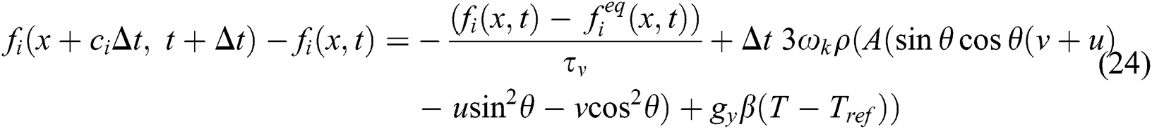
It’s evident from the equations above that magnetic field affects the force term. So, the total body forces acting in x and y directions are called ‘external force’ in Eq. (10). It should be noted that all the variables in the force term of LBM must be dimensionless [3], and hence the following expressions can be presented:


Here, A is expressed as in the following:

Eq. (10) now takes the form of:
Practical implementation requires the two main macroscopic physical quantities,  and u, to derive the boundary conditions. In the case of LBM, boundary conditions are written as the distribution function (DF). In LBM, it is important to determine the DFs at nodes of the boundary as per the macroscopic boundary conditions. By doing this, it determines the stability and precision of the calculation [36].
4.5.1 Boundary Conditions for Fluid Flow
Bounce-back boundary condition is applied on all four no-slip solid walls. This condition specifies the incoming directions of the distribution function to be reverse of the outgoing distribution function at the boundary position after the collision. The boundary conditions for the flow are [31]:
At east (right) wall:  ,
,  , and
, and  .
.
At west (left) wall:  ,
,  , and
, and  .
.
At north (top) wall:  ,
,  and
and  .
.
At south (bottom) wall:  ,
,  and
and  .
.
Here, m and n show lattice for length and height, respectively, of the domain.
4.5.2 Thermal Boundary Conditions
The adiabatic condition is applied on the east and west walls of the cavity. The south wall is heated ( ) while the north wall is kept cold (
 ).
).
At cold north wall:  ;
;  ;
;  .
.
At heated south wall:  ;
;  ;
;  . Here
  is used for the 2nd-order Zou-He boundary conditions [37,31], and W denotes to the block separation distance.
For adiabatic west wall:  , for i=1 to 4.
For adiabatic east wall:  , for i = 1 to 4.
In convective heat transfer problem, Nusselt number (Nu) is an essential dimensionless parameter that describes the rate of heat transport occurring due to temperature difference between the top and bottom walls. The average Nusselt number ( ) and the local Nusselt number (Nu) at the hot wall is formulated as in the following:


where L = 2H is the horizontal length of the cavity.
The iterative process in the present single-relaxation-time LBM is terminated when the temperature and the velocity field satisfy the convergence criteria. This is defined as in the following [37,31]:

where n is the iteration index,  is the temperature T or the velocity u, and the sum is applied over the entire domain.
5 Code Validation and Grid Independent Test
The validation programming codes consist of several simulated results, and each of those is either compared with benchmark data or analyzed with established theorem. The validation schemes are performed to observe the accordance in  , streamlines, isotherms, and the influence of the magnetic field effect. At first, the present code is validated with the results of the natural convection flow in a side heated square cavity [5]. An excellent agreement with some literature is presented in Tab. 1 comparing the average rate of heat transfer
  . Next, a successful comparison of the natural convection flow in a side heated square cavity with the magnetic field effect is shown in Tab. 2, which proves further confidence on the validation in terms of Ha numbers. The values in Tab. 2 represent the
  numbers, for which additional Ra numbers are also taken into account to match with the available results of [5,38,27].
Table 1: Validation of Simulated results for  numbers at different
  numbers

Table 2: Comparison of  numbers at different
  numbers under various magnetic field strengths

There is one physical validation performed comparing isotherms with the results of Kao et al. [2] as shown in Fig. 3, where evidential similarities can be observed. All of these comparisons (Tabs. 1 and 2, and Fig. 3) show that the present study has a good agreement with previous works, and is suitable for future developments. Fig. 3 shows no bifurcation to secondary instability in the considered flow condition, i.e.,  and Pr = 0.71, as it was observed in the work of Kao et al. [2].
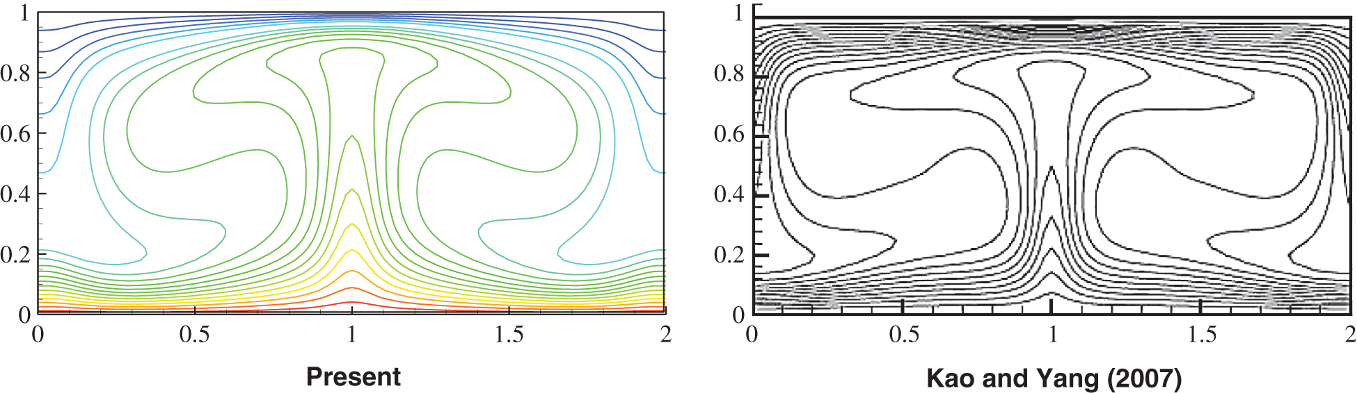
Figure 3: Temperature contours validation with Kao et al. [2], at  , for
, for 
Although the grid-independent test is one of the pre-requisites to show the accuracy of the simulated results, the obligation of performing this test is seldom mentioned in the literature. Grid independent test is conducted to demonstrate the improvement of the results by using sequentially smaller cell (lattice) sizes for the calculation. Tab. 3 shows the elaborated data. The calculations should approach to more accurate answer as the mesh becomes finer. In conventional computational fluid dynamics (CFD) approach, the simulation technique starts with a coarse mesh at the commencement, and gradually refines it until the changes observed in the outputs are smaller than the pre-defined acceptable error. This methodology creates two problems. First off, it is an arduous task for any CFD tool to achieve the identical single coarse mesh for some specific problems, particularly at different time steps or when the time is pressing. Secondly, refining mesh may increase the time-scale to complete the simulation performance, which is not an appreciable characteristic of any LBM scheme, considering the time and cost constraints. The purpose of grid-independent test is to ensure similar fundamental solution independent of either grid size or any scale factor.
Table 3: Grid independence confirmation (at  )
)

The grid-independent tests for the present codes are done by calculating the  on the heated wall. The simulation is run for each case from quiescent commencement until any changes occurred in the
  . Tab. 3 shows more detailed results of grid-independent test. Two-dimensional uniform rectangular mesh distribution is used in the work. Results of 200 × 100 grid size are used for analysis throughout this paper.
6.1 Impact of Buoyancy Parameter (Ra)
Two-dimensional fluid flow and heat transfer in the existence of a magnetic field is thoroughly studied in this research. LBM is applied to perform numerical simulation inside a rectangular cavity filled with water and oil, corresponding to their unique Pr numbers of 10 and 70, respectively. Inclusion of Ra establishes the connection between buoyancy and viscosity within a fluid. In this paper, four different Ra numbers ( are considered to compare the flow behaviour. It should be noted that for
  , the fluid flow doesn’t reach the fully developed turbulence state [2]. To justify this statement,
  is also considered.
Figs. 4a and 4b illustrate the influences of the Rayleigh number. For the analysis of Rayleigh number effect, Pr = 10 and  is considered in this section with different Ra values and different Ha values. It is seen from the streamline and isotherm contours that all the contour lines are symmetric concerning the vertical midline of the enclosed space when
  . The buoyancy has a supporting influence on natural convection; however, the Lorentz force shows a contrasting influence. The influence of Ra =
 is more distinct on the transfer mechanism. At Ha = 0, with no influence of electromagnetic force, for all the values of Ra, the bi-cellular flow pattern symmetrically divided the rectangular cavity from the vertical centre line, this is seen in Fig. 4a. However, no bifurcation to secondary instability occurs under the flow conditions
  to
to ,
,  ,
,  , and,
  to
to  . At
. At  re-circulation zones occur mostly close to the boundary wall. From
  to
to  , the re-circulation zones occur comparatively in the middle of the domain. These streamlines indicate that there is more presence of fluid throughout the domain at
  compared to other Ra
  value, and
  shows very poor presence of fluid throughout the domain. In addition, it is observed that the periodic unsteady flow at
  and
and  breaks some symmetries and retain most of the symmetries. At this value of Ha, the temperature contours (isotherms) show changes with the increasing value of
  . At low Rayleigh number, conduction is the main method of heat and flow transfer. At
  , the isotherm contour lines are completely straight lines which indicate that heat transfer at this stage is low since convective heat transfer is not very possible in this scenario.
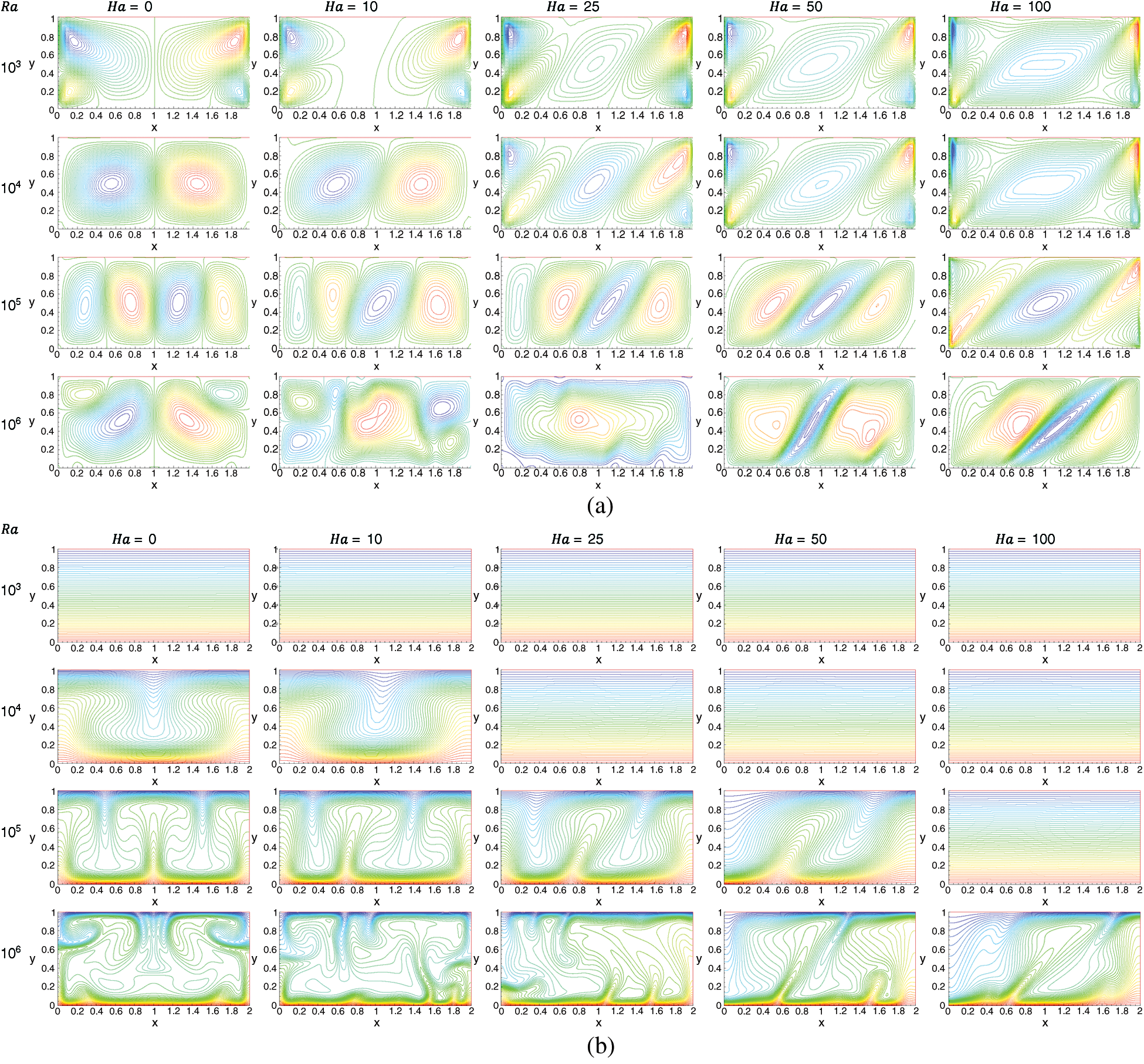
Figure 4: Influence of Buoyancy Parameter (Ra) on the flow pattern, (a) Streamlines,  . (b) Isotherms, Pr = 10,
The highest value of the stream function increases with the increasing value of  ; this means that flow travels quicker since natural convection is stronger and the isotherm contour lines are distorted [5,40,41,42]. Since higher Rayleigh number causes more dominant buoyancy force than viscous force, the convective transfer inside the enclosure becomes very strong. An increase in re-circulation results in cold fluid having a downward motion; hence the convective heat transfer is the fundamental method of heat transfer. Increasing the Ha value has a pure conduction regime for all
  values. Due to the interaction between Lorentz and Buoyancy force decrease in velocities happen, and convection heat transfer is suppressed. Additionally, it is seen that conductive heat transfer enhances with higher
  values, thus suppression of convective heat transfer requires a higher magnetic field at higher Rayleigh number. The variation in the temperature distribution profile appears to be more for increased magnetic field. The isothermal walls vanish from the thermal boundaries signifying the undermined function of the convection in the heat and flow transfer method. Moreover, results illustrate that the highest value of stream function reduces amid enhancement of Ha value.
Moreover, streamline and isotherm contours bend  as the Hartmann number increases since an increase in Hartmann number intensifies the electromagnetic force, and the angle of the electromagnetic force,
  is set at
  . At
. At  , no influence of the inclined angle is realized as the electromagnetic force is not active here, and Ha = 50 and 100 show most influence of the electromagnetic force.
6.2 Effect of Prandtl Number (Pr)
The Pr number is a paradigm of a non-dimension parameter which can explain the intrinsic property of certain fluids. Fluids with lower Pr are free-flowing fluids with higher thermal conductivity, and on the other hand, higher Pr means fluids have a higher viscosity, and hence the momentum transport remains superior to the heat transport. As a consequence, those types of fluids are problematic to study heat transfer applications. But, to be in accord with the definition of Pr and heat transfer theory, the cohort of fluids have different Pr in this research.
Figs. 5 and 6 depict the effects of Pr value on the streamlines and isotherms, at various Ra, Ha and  . It can be observed that both the concentration and temperature distributions decreased with increasing Pr value. The streamlines showed that the flow showcases behaviour aligned with the gravitational constant (
 ) if the materials inside the cavity vary, which means at different Pr value. By observing this behaviour, it can be inferred that the increment in Pr forces fluid to move from the lower surface and the downside of the enclosure, resulting in a decrement in both flow density and temperature distribution [3,43].
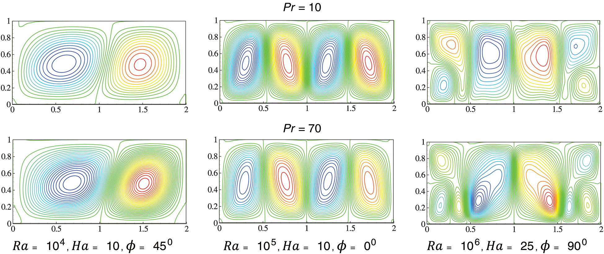
Figure 5: Streamlines for two different Pr

Figure 6: Isotherms for two different Pr
Figs. 5 and 6 consider three cases for the analysis of the Prandtl number, i)  ,
,  ,
,  ; ii)
; ii)  ,
,  ,
,  ; and; iii)
  ,
,  ,
,  ; to show the influence of Prandtl number on the flow and heat transfer mechanism. For the case (i), the transfer of flow and heat is almost completely conductive at Pr = 70 and a very small amount of flow and heat transfer follow the convective transfer mechanism. If the value of the Prandtl number is decreased the convective nature of transfer start to increase. Then, case ii) shows that the conductive nature of the transfer is highest at Pr = 70 compared to the other value of the Prandtl number. In this scenario, the convective nature of the transfer is mostly seen in the middle of the domain, and conductive nature of the transfer is observed close to the thermal walls. Afterwards, case (iii) shows mostly convective nature of the transfer, as it has a high Rayleigh number. However, there is still some conductive nature of transfer in this case, mostly close to the thermal walls.
6.3 Average Rate of Heat Transfer
A heat transfer analysis has been conducted to understand the effect of magnetic field on RB convection in the rectangular cavities. It is found that Nu increases as the buoyancy parameter Ra increases, but the Nu exhibits the opposite behaviour as Ha number increases. It means with an augmentation of Ha number, the  decreases. The distribution of Nu on the heated wall for different Ha and Pr numbers are presented in Figs. 7 and 8 for
  to
to  , where a large number of fluctuations can be observed due to increment in the buoyancy parameter (Ra number).
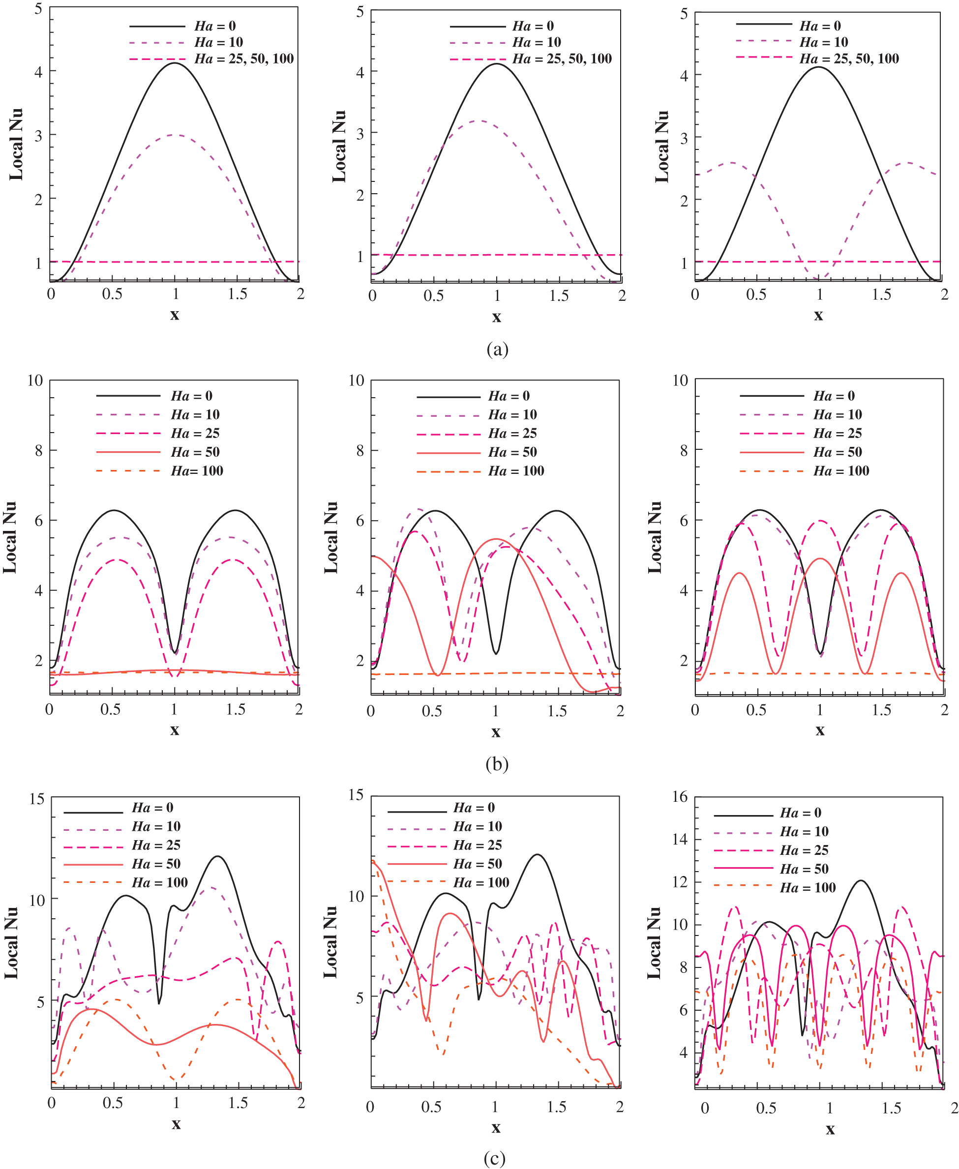
Figure 7: Local Nu number distribution on the heated wall at  at
at  (column wise, left to right) for
 ,
, 

Figure 8: Local Nu number distribution on the heated wall at  at
at  (column wise, left to right) for
According to Figs. 7 and 8, the aforementioned theory can be rationalised as the Nu number falls with increasing Ha numbers. However, the behavioural changes are not similar for different Pr values since all fluids don’t respond identically to heat transfer applications due to physicochemical differences, for Pr = 10, 70. For RB convection, the bell-shaped curve signifies the mid-section to be the most influential zone as the heat source is placed at the bottom wall, which results in forming the appearance of the symmetricity.
Fig. 7 shows the characteristics of the Nusselt number at Pr = 10 for Ra =  . At
. At  (row A) it is seen that convective transfer is greater than four times than the conductive transfer at peak without any electromagnetic force applied (
 ). With a slight increase in the Hartmann number, Ha = 10, the peak value of convective transfer reduces a lot. Then, having an
  inclined angle of the electromagnetic force increases the convective transfer mechanism in one part of the domain; in this case, the increase is in the left-hand side of the domain. The inclined angle of electromagnetic force at
  changed the convective transfer significantly, the peak value of conductive transfer increases in massive amount. In other Hartmann numbers,
  , the convective and conductive transfer are the same keeping the Nusselt number values at 1 throughout the domain. At
  (Row B), more convective transfer occurs throughout the domain for all the values of Hartmann number except
  . This is due to higher Rayleigh number. But at higher Hartmann number
  100, the conductive and convective transfer remains the same as the Nusselt number is 1 in this case. The peak values of Nusselt numbers are higher in this case compared to
  , which is the indication of higher convective transfer for
  . Then, due to the value of
  additional fluctuations are seen in the transfer mechanism because of the positioning of the electromagnetic force.
  shows fewer fluctuations compared to
  . One massive different has occurred in this case for Ha = 50 at
  ; the convective and conductive transfer remains almost the same throughout the domain with a very small change in the vertical centreline on the domain. At
  (Row C), a very little conduction transfer happens compared to convective transfer. Even at very high Hartmann number, the conductive transfer is very low compared to convective transfer. Again, a very little conductive transfer is observed at
  , and it is very negligible. The peak values of Nusselt number are extremely high in this scenario compared to
  . These illustrations show that most of the transfers occur due to convection at this stage. Once again, fluctuations are seen due to the values of
  . From these observations, it can be confirmed that the positioning of electromagnetic force can have a significant impact on the transfer of flow and heat.
Fig. 8 shows the characteristics of Nusselt number at Pr = 70 for Ra =  . At
. At  (row A) it is seen that convective transfer is greater than almost four times than the conductive transfer at peak without any electromagnetic force applied,
  . With a slight increase in the Hartmann number, Ha = 10, the peak value of convective transfer reduces a massive amount; this scene was completely different for the same case in Pr = 10. Then, having an
  inclined angle of the electromagnetic force increases the convective transfer mechanism in one part of the domain slightly; in this case, the increase is in the right-hand side of the domain. The inclined angle of electromagnetic force at
  changes the convective transfer significantly, the peak value of conductive transfer increases in massive amount. In other Hartmann numbers,
 , the convective and conductive transfer are the same keeping the Nusselt number values at 1 throughout the domain. The same scenario is seen in Fig. 7 for
  at
at  , which indicates that the characteristics of the Nusselt number don’t change very much with a change in Prandtl number at
  for these Hartman numbers. At
  (Row B), more convective transfer occurs throughout the domain for all the values of Hartmann number except
  . This is due to higher Rayleigh number. But at higher Hartmann number
  100, the conductive and convective transfer remains the same as the Nusselt number is 1 in this case. The peak values of Nusselt numbers are higher in this case compared to
  , which is the indication of higher convective transfer for
  . Then, due to the value of
  additional fluctuations are seen in the transfer mechanism because of the positioning of the electromagnetic force.
  shows fewer fluctuations compared to
  . Similar results are seen in Fig. 7 for
  but. In general, the phenomena of the transfer mechanism are the same as it is seen for
  at
at  in Fig. 7. At
  (Row C), a very little conduction transfer happens compared to convective transfer. Even at very high Hartmann number, the conductive transfer is very low compared to convective transfer. A very little conductive transfer is observed at
  , and it is very negligible. The peak values of Nusselt number are extremely high in this scenario compared to
  . These illustrations show that most of the transfer occurs due to convection at this stage. Again, fluctuations are seen due to the value of
  . In this case, with
  fluctuations are more compared to the same scenario at
  (Fig. 7). Once again, it can be confirmed that the positioning of electromagnetic force can have a significant impact on the transfer of flow and heat.
Fig. 9 depicts the values of the  as considered dimensionless parameters varied within the prevalent domain. The rate of heat transfer increases as Ra value increases, validating the results against Kefayati et al. [3], illustrated in Fig. 4, the Ha value had an influential impact on the heat transfer. At low Ra value (e.g.,
  ), when the magnetic field does not exist, the
  at Pr = 10 and Pr = 70 have different patterns since the fluids of former two Pr value (10) have analogous properties than the fluid which possesses Pr = 70.
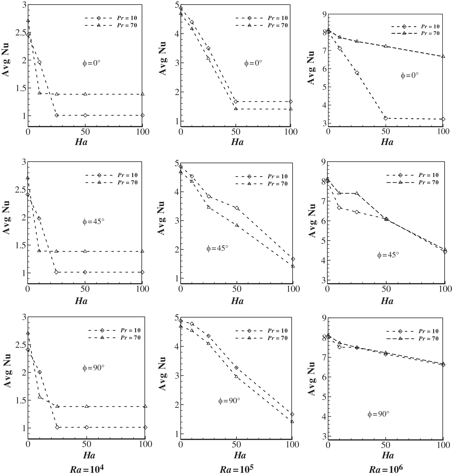
Figure 9:  number distribution on the heated wall at different
  (column-wise arrangement) and
  numbers for three types of fluid
Meanwhile, the impact of inclined angle ( ) plays a pivotal role in controlling the MHD flow in RB convection. Fig. 9 reports the alterations in the behaviour at
  = 0, 45, 90. At Ra =
  , the values of
  depends favourably for low Ha number, after that the rate of changes become almost constant, confirming the thermal equilibrium stage. As Ra increases, there are significant declinations in the average rate of heat transfer for different fluids due to instability reported earlier. Furthermore, at Ra =
  , the rate of heat transfer displays an erratic trend at
  = 0, 45, but, this trend is not visible at
  = 90.
= 90.
The study investigates the influence of magnetic field on RB convection in an enclosed square cavity which has been analyzed by LBM. The research has been carried out for two different fluids varying Pr numbers. To sum up, the following findings can be highlighted:
•Validation with previous research works substantiates that LBM can offer enhanced accuracy to study RB convection by coalescing with the magnetic field.
•The heat transfer applications and flow characteristics inside the enclosed cavity depend largely upon the magnetic field strength (Ha), inclined angles ( ), and Ra values. Deterioration of heat transfer is observed for an increment of Ha value at various Ra and Pr values.
•The impact of magnetic field is insignificant for low Ra value, as the isotherms become parallel to each other due to surpassing of RB convection, and the heat transfer inside the enclosure is mostly dominated by the conduction. For Ra =  , isotherms are always parallel, and at
  , the parallel isotherms can be seen for
  . At
. At  to
to  , this characteristic is not visible as a result of higher values of the buoyancy parameter, which formed instability and oscillation.
•Ha numbers have a significant impact on Nu value for different fluids, where unstable oscillatory flows cease to exist at  for Ha > 10 in most of the cases.
•At Ra =  , the average rate of heat transfer declines inconsistently, and at
  , water (Pr = 10) has the most declining rate.
Acknowledgement: The second author would like to acknowledge to the North South University for the partial support as a Research Assistant (Grant No. NSU-RP-18-067)
Funding Statement: The author(s) received no specific funding for this study.
Conflicts of Interest: The authors declare that they have no conflicts of interest to report regarding the present study.
References
1. Howle, L. (1996). A comparison of the reduced Galerkin and pseudo-spectral methods for simulation of steady Rayleigh-Bénard convection. International Journal of Heat and Mass Transfer, 39(12), 2401–2407. DOI 10.1016/0017-9310(95)00346-0.
2. Kao, P., Yang, R. (2007). Simulating oscillatory flows in Rayleigh-Bénard convection using the lattice Boltzmann method. International Journal of Heat and Mass Transfer, 50(17), 3315–3328. DOI 10.1016/j.ijheatmasstransfer.2007.01.035.
3. Kefayati, G., Gorji, M., Sajjadi, H., Domiri Ganji, D. (2013). Investigation of Prandtl number effect on natural convection MHD in an open cavity by Lattice Boltzmann Method. Engineering Computations, 30(1), 97–116. DOI 10.1108/02644401311286035.
4. Savithiri, S., Pattamatta, A., Das, S. (2017). Rayleigh-Benard convection in water-based alumina nanofluid: a numerical study. Numerical Heat Transfer, Part A: Applications, 71(2), 202–214. DOI 10.1080/10407782.2016.1257302.
5. Sheikholeslami, M., Gorji-Bandpy, M., Ganji, D. (2014). Lattice Boltzmann method for MHD natural convection heat transfer using nanofluid. Powder Technology, 254, 82–93. DOI 10.1016/j.powtec.2013.12.054.
6. Tagawa, T., Ujihara, A., Ozoe, H. (2003). Numerical computation for Rayleigh--Benard convection of water in a magnetic field. International Journal of Heat and Mass Transfer, 46(21), 4097–4104. DOI 10.1016/S0017-9310(03)00223-0.
7. Zhao, J., Cai, W., Jiang, Y. (2019). Study on frequency patterns of 2D square Rayleigh--Bénard convection filled with air. European Journal of Mechanics-B/Fluids, 74, 280–290. DOI 10.1016/j.euromechflu.2018.09.002.
8. Shan, X. (1997). Simulation of Rayleigh-Bénard convection using a lattice Boltzmann method. Physical Review E, 55(3), 2780.
9. Wilkes, J. O., Churchill, S. W. (1966). The finite-difference computation of natural convection in a rectangular enclosure. AIChE Journal, 12(1), 161–166. DOI 10.1002/aic.690120129.
10. Boland J., Layton W. (1990). An analysis of the finite element method for natural convection problems. Numerical Methods for Partial Differential Equations, 6(2), 115–126. DOI 10.1002/num.1690060202.
11. Misra, D., Sarkar, A. (1997). Finite element analysis of conjugate natural convection in a square enclosure with a conducting vertical wall. Computer Methods in Applied Mechanics and Engineering, 141(3–4), 205–219. DOI 10.1016/S0045-7825(96)01109-7.
12. Roy, S., Basak, T. (2005). Finite element analysis of natural convection flows in a square cavity with non-uniformly heated wall(s). International Journal of Engineering Science, 43(8–9), 668–680. DOI 10.1016/j.ijengsci.2005.01.002.
13. Hortmann, M., Perić, M., Scheuerer, G. (1990). Finite volume multigrid prediction of laminar natural convection: bench-mark solutions. International Journal for Numerical Methods in Fluids, 11(2), 189–207. DOI 10.1002/fld.1650110206.
14. Oztop, H. F., Abu-Nada, E. (2008). Numerical study of natural convection in partially heated rectangular enclosures filled with nanofluids. International Journal of Heat and Fluid Flow, 29(5), 1326–1336. DOI 10.1016/j.ijheatfluidflow.2008.04.009.
15. Ashorynejad, H. R., Mohamad, A. A., Sheikholeslami, M. (2013). Magnetic field effects on natural convection flow of a nanofluid in a horizontal cylindrical annulus using Lattice Boltzmann method. International Journal of Thermal Sciences, 64, 240–250. DOI 10.1016/j.ijthermalsci.2012.08.006.
16. Ottolenghi, L., Prestininzi, P., Montessori, A., Adduce, C., La Rocca, M. (2018). Lattice Boltzmann simulations of gravity currents. European Journal of Mechanics-B/Fluids, 67, 125–136. DOI 10.1016/j.euromechflu.2017.09.003.
17. Bhardwaj, S., Dalal, A. (2018). Sweeping of the entrapped fluid out of the groove in a three-dimensional channel using lattice Boltzmann method. European Journal of Mechanics-B/Fluids, 72, 328–339. DOI 10.1016/j.euromechflu.2018.07.001.
18. Ghaderi, A., Kayhani, M. H., Nazari, M., Fallah, K. (2018). Drop formation of ferrofluid at co-flowing microcahnnel under uniform magnetic field. European Journal of Mechanics-B/Fluids, 67, 87–96. DOI 10.1016/j.euromechflu.2017.08.010.
19. Succi, S. (2001). The lattice Boltzmann equation: for fluid dynamics and beyond. Oxford University Press, Oxford, UK.
20. Pattison, M., Premnath, K., Morley, N., Abdou, M. (2008). Progress in lattice Boltzmann methods for magnetohydrodynamic flows relevant to fusion applications. Fusion Engineering and Design, 83(4), 557–572. DOI 10.1016/j.fusengdes.2007.10.005.
21. Hasanpour A., Farhadi M., Sedighi K., Ashorynejad H. R. (2012). Numerical study of Prandtl effect on MHD flow at a lid-driven porous cavity. International Journal for Numerical Methods in Fluids, 70(7), 886–898. DOI 10.1002/fld.2719.
22. Alchaar, S., Vasseur, P., Bilgen, E. (1995). The effect of a magnetic field on natural convection in a shallow cavity heated from below. Chemical Engineering Communications, 134(1), 195–209. DOI 10.1080/00986449508936332.
23. Dellar, P. J. (2002). Lattice kinetic schemes for magnetohydrodynamics. Journal of Computational Physics, 179(1), 95–126. DOI 10.1006/jcph.2002.7044.
24. Sathiyamoorthy, M., Chamkha, A. (2010). Effect of magnetic field on natural convection flow in a liquid gallium filled square cavity for linearly heated side wall(s). International Journal of Thermal Sciences, 49(9), 1856–1865. DOI 10.1016/j.ijthermalsci.2010.04.014.
25. Nemati, H., Farhadi, M., Sedighi, K., Fattahi, E., Darzi, A. (2010). Lattice Boltzmann simulation of nanofluid in lid-driven cavity. International Communications in Heat and Mass Transfer, 37(10), 1528–1534. DOI 10.1016/j.icheatmasstransfer.2010.08.004.
26. Pirmohammadi, M., Ghassemi, M. (2009). Effect of magnetic field on convection heat transfer inside a tilted square enclosure. International Communications in Heat and Mass Transfer, 36(7), 776–780. DOI 10.1016/j.icheatmasstransfer.2009.03.023.
27. Sajjadi, H., Delouei, A. A., Sheikholeslami, M., Atashafrooz, M., Succi, S. (2019). Simulation of three dimensional MHD natural convection using double MRT Lattice Boltzmann method. Physica A: Statistical Mechanics and its Applications, 515, 474–496. DOI 10.1016/j.physa.2018.09.164.
28. Mohamad, A., El-Ganaoui, M., Bennacer, R. (2009). Lattice Boltzmann simulation of natural convection in an open ended cavity. International Journal of Thermal Sciences, 48(10), 1870–1875. DOI 10.1016/j.ijthermalsci.2009.02.004.
29. Peng, Y., Shu, C., Chew, Y. T. (2003). Simplified thermal lattice Boltzmann model for incompressible thermal flows. Physical Review E, 68(2), 026701. DOI 10.1103/PhysRevE.68.026701.
30. Himika, T. A., Hasan, M., Molla, M. (2016). Lattice Boltzmann simulation of airflow and mixed convection in a general ward of hospital. Journal of Computational Engineering, 2016(2), 5405939. DOI 10.1155/2016/5405939.
31. Hassan, S., Himika, T. A., Molla, M. M., Hasan, M. F. (2019). Lattice Boltzmann simulation of fluid flow and heat transfer through partially filled porous media. Journal of Computational Engineering and Physical Modeling, 2(4), 21–30.
32. Seta, T., Takegoshi, E., Okui, K. (2006). Lattice Boltzmann simulation of natural convection in porous media. Mathematics and Computers in Simulation, 72(2–6), 195–200. DOI 10.1016/j.matcom.2006.05.013.
33. Perumal, D. A., Yadav, A. K. (2018). Computation of fluid flow in double sided cross-shaped lid-driven cavities using Lattice Boltzmann method. European Journal of Mechanics-B/Fluids, 70, 46–72. DOI 10.1016/j.euromechflu.2018.01.006.
34. Guo, Z., Zhao, T. S. (2002). Lattice Boltzmann model for incompressible flows through porous media. Physical Review E, 66(3), 036304. DOI 10.1103/PhysRevE.66.036304.
35. Wang, L., Mi, J., Guo, Z. (2016). A modified lattice Bhatnagar–Gross–Krook model for convection heat transfer in porous media. International Journal of Heat and Mass Transfer, 94, 269–291. DOI 10.1016/j.ijheatmasstransfer.2015.11.040.
36. Guo, Y., Bennacer, R., Shen, S., Ameziani, D. E., Bouzidi, M. (2010). Simulation of mixed convection in slender rectangular cavity with lattice Boltzmann method. International Journal of Numerical Methods for Heat & Fluid Flow, 20(1), 130–148. DOI 10.1108/09615531011008163.
37. Hasan, M. F., Himika, T. A., Molla, M. M. (2017). Lattice Boltzmann simulation of airflow and heat transfer in a model ward of a hospital. Journal of Thermal Science and Engineering Applications, 9(1), 011011. DOI 10.1115/1.4034817.
38. de Vahl Davis, G. (1983). Natural convection of air in a square cavity: a bench mark numerical solution. International Journal for Numerical Methods in Fluids, 3(3), 249–264. DOI 10.1002/fld.1650030305.
39. Rudraiah, N., Barron, R. M., Venkatachalappa, M., Subbaraya, C. K. (1995). Effect of a magnetic field on free convection in a rectangular enclosure. International Journal of Engineering Science, 33(8), 1075–1084. DOI 10.1016/0020-7225(94)00120-9.
40. Sheikholeslami, M., Haq, R.u, Shafee, A., Elaraki, Z. Li, Y., G. et al. (2019). Heat transfer simulation of heat storage unit with nanoparticles and fins through a heat exchanger. International Journal of Heat and Mass Transfer, 135, 470–478. DOI 10.1016/j.ijheatmasstransfer.2019.02.003.
41. Sheikholeslami, M., Jafaryar, M., Shafee, A., Babazadeh, H. (2020). Acceleration of discharge process of clean energy storage unit with insertion of porous foam considering nanoparticle enhanced paraffin. Journal of Cleaner Production, 261, 121206. DOI 10.1016/j.jclepro.2020.121206.
42. Sheikholeslami, M., Jafaryar, M., Abohamzeh, E., Shafee, A., Babazadeh, H. (2020). Energy and entropy evaluation and two-phase simulation of nanoparticles within a solar unit with impose of new turbulator. Sustainable Energy Technologies and Assessments, 39, 100727. DOI 10.1016/j.seta.2020.100727.
43. Himika, T. A., Hassan, S., Hasan, M. F., Molla, M. M. (2020). Lattice Boltzmann simulation of MHD Rayleigh-Bénard convection in porous media. Arabian Journal for Science and Engineering, 37(1), 1–21. DOI 10.1007/s13369-020-04812-z.
 | This work is licensed under a Creative Commons Attribution 4.0 International License, which permits unrestricted use, distribution, and reproduction in any medium, provided the original work is properly cited. |