DOI:10.32604/EE.2020.012362
| Energy Engineering DOI:10.32604/EE.2020.012362 | |
| Review |
A Review of Leakage and Dispersion of LNG on the Ground
1School of Civil Engineering and Geomatics, Southwest Petroleum University, Chengdu, 610500, China
2School of Engineering, Southwest Petroleum University, Nanchong, 631001, China
3Sales Department, Petro China Southwest Oil & Gas Field Company, Chengdu, 610065, China
*Corresponding Author: Yiqing He. Email: ds_xyz@sina.com
Received: 27 June 2020; Accepted: 25 August 2020
Abstract: Based on the analysis of the whole process of LNG spill on land, the research methods of LNG pool expansion and heavy gas diffusion are summarized and analyzed. This paper reviews the experimental and analytical work performed to data on spill of LNG. Specifically, experiments on the spill of LNG onshore, as well as experiments and numerical study on heavy gas dispersion. Pool boiling and turbulence model are described and discussed, as well as models used to predict dispersion. Although there have been significant progress in understanding the behavior of LNG spills, technical knowledge gaps to improve hazard prediction are still identified. Some of the gaps can be addressed with current modeling and testing capabilities. Finally, a discussion of the state of knowledge, and recommendations to further improvement the understanding of the behavior of LNG spills onshore.
Keywords: LNG; pool spread; heavy gas dispersion; experiments; modeling; review
Studies on Liquefied Natural Gas (LNG) behavior have been undertaken by a number of organizations over a period of more than 40 years. With the continuous and rapid development of global LNG market trade, the influence of LNG exporting countries will be enhanced in the future [1]. LNG is not only used in power generation, vehicle use, civil gas supply, industrial gas and methanol and other chemical raw materials preparation, but also plays an important role in adjusting energy structure and promoting energy conservation and emission reduction [2]. Recently, there has been considerable interest concerning possible risks associated with the storage, transportation, and handling of LNG due the widely expanded the LNG market.
According to the safety data sheet, LNG is flammable. At the same time, once LNG leaks, it will boil and vaporize immediately, and mix with air to form combustible cloud. When the concentration of this kind of cloud is within the explosion range of 5.3–14.0%, it will explode when encountering fire source, and produce shock wave, which will cause certain damage or damage to the surrounding personnel and facilities. In order to solve the problem of hazard prediction, it is necessary to combine experimental, numerical and analytical work. Many researchers have carried out a lot of experiments on the leakage of LNG on the water surface, but few experiments have been carried out on the leakage to the ground. The main factors that affect the flow and diffusion of LNG pool and vapor diffusion near the surface are: ground roughness, geographical situation, surface slope. (1) The higher ground roughness, the greater resistance to the vapor dispersion near the surface, and the more unfavorable to the vapor dispersion behavior; (2) the geographical situation has a greater impact on the dispersion behavior of LNG vapor, which is due to the heavy gas dispersion behavior at the initial stage of vapor dispersion after LNG leakage, and the dispersion should be carried out close to the surface; (3) The slope has little effect on the dispersion of LNG vapor. However, when the wind speed is very small, the LNG vapor will spread along the downhill direction due to gravity. The larger the slope, the faster the dispersion. Wang et al. [3] used ALO-HA software to conduct numerical calculation on different types of ground (concrete floor, wet sand layer and dry sand layer) of LNG leakage, and concluded that the methane dispersion UFL, LFL and distance of LNG leakage to concrete ground in the up and down wind direction were the farthest, followed by wet sand layer and dry sand layer. Chen [4] used FLUENT to study the influence of ground roughness and heat flux on the distribution of methane volume fraction (ULF, LFL, 1/2LFL) in the process of LNG leakage and dispersion. On the other hand, the situation of LNG leakage and dispersion on the water surface and on the ground is different. When LNG leaks to the ground (such as accidental spillover), it will boil violently at first, and then the evaporation rate will rapidly decrease to a fixed value, which depends on the thermal properties of the ground and the heating conditions of the surrounding air. When LNG spills over the water, the convection in the water is very strong enough to keep the evaporation rate in the range involved unchanged, and the overflow range will continue to expand until the total evaporation of gas equals the total amount of LNG leaked. ANAY [5] summarized the experiments of LNG diffusion, pool boiling and steam fire after leakage on water and ground, studied the models of pool diffusion, evaporation and dangerous distance prediction, and obtained the characteristics and differences of LNG diffusion and evaporation on water and ground. Lin [6] used FLACS to study the diffusion process of LNG under the same meteorological conditions on water and ground, and obtained that the liquid phase dispersion rate on the water surface is greater than that on the ground, the dispersion distance is larger than that on the ground, and the combustion area covers a wider area than the ground.
LNG transportation is mostly by ship, as a result, most of the hazardous analysis are based on large scale experiments performed in the 1970s and 1980s which are modeling LNG leakage on water. However, a surprisingly development of LNG industry in landlocked countries such as China and Korea had brought this issue onshore. The LNG industry chain involves upstream natural gas liquefaction plants, midstream LNG transport tankers/ships, large LNG receiving terminals, and downstream satellite stations and gas stations [7]. The storage scale is large (e.g., Tangshan LNG tank in China has volume of 20 × 104 m3), and its storage and transportation facilities are generally a major source of danger.
The potential hazards associated with LNG are varied. In the event of leakage, hazards may occur, including cryogenic tissue damage, pool fire, deflagrations, detonations and vapor cloud fires [8]. Due to its extremely cold temperature, materials may become embrittlement by direct contact. When LNG comes in contact with ground surface, cryogenic liquid boils off vigorously in response to the significant difference between the ground temperature and boiling point (boiling point of LNG is −162°C) [9]. Since LNG vapor disperse in the air, there are also thermal hazards form different combustion events such as vapor cloud fire or explosion. Therefore, it is necessary to conduct safety evaluation and analysis of LNG leakage hazards. Before this, it is necessary to understand the whole process of ground LNG leakage, as shown in Fig. 1.
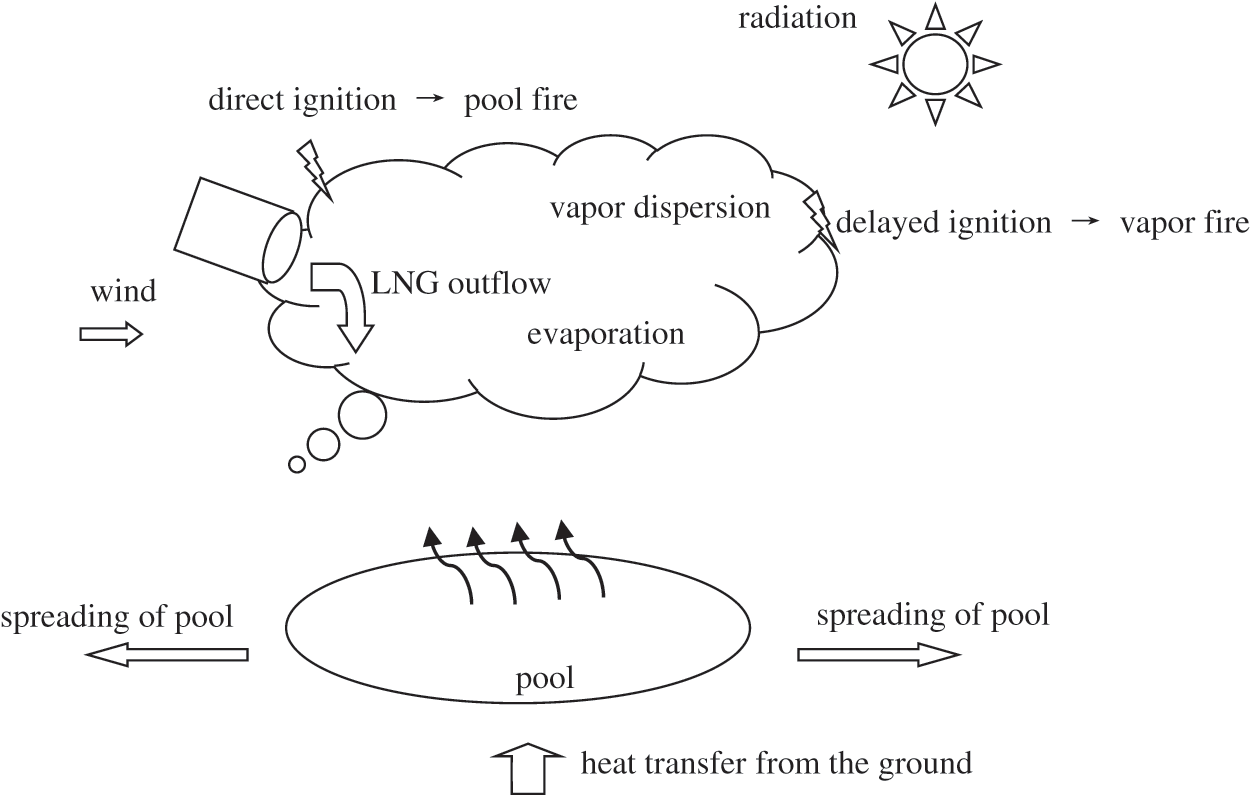
Figure 1: The whole process of LNG leakage on ground
As can be seen from Fig. 1, the LNG leakage process can be divided into four stages [10]: Leakage (LNG outflow), evaporation, spreading of pool and vapor dispersion. The output of the pool formation (flow state, phase state, pool area, evaporation rate, etc.) provides initial boundary conditions for the dispersion of vapor clouds. However, for such a complete and complex process, including the leakage forms, two-phase change thermodynamic process and kinetic process, and the vapor cloud dispersion process, etc., is lack of systematic research. At present, there are also software such as FLACS can be used to model process of leakage of LNG, but the whole simulation process is mostly empirical methods, which means there are many hypotheses. If the process of leakage exceeds its hypothesis range, there will be a large error. Therefore, how to accurately simulate the formation of LNG leakage and process of vapor dispersion will provide a reliable basis for LNG leakage safety assessment and extreme risk management [11]. Saleem [12] simulated the process of evaporation and dispersion in full-scale LNG storage tank. Lee model was used to simulate phase change evaporation. The transition from surface evaporation to nuclear boiling of critical wall superheat was obtained, and the temperature was estimated to be 2.5–2.8 K. Gopalaswami [13] successfully simulated the process of LNG leakage, evaporation and vapor dispersion in the water.
When low-temperature LNG leakage out of the storage tank, a large temperature difference (about 180°C) causes intense heat exchange between LNG and the environment, as a result, the LNG boils off violently [14–16]. In the initial stage of the leakage, some of the LNG droplets will flash rapidly into the air, while the others will drop to the ground to form a pool. During the vapor dispersion process, the pool is affected by environmental wind, solar radiation, ground roughness and other factors, and its evaporation rate is constantly changing [17]. At the same time, the temperature of the ground is continuously reduced, so the boiling phenomenon of the pool will go from violent to slow. At present, the research methods mainly include experimental research and numerical simulation research.
Since LNG is flammable at low temperature, the experimental device is complicated and has high safety requirements. During the experiment, the liquid deposit is continuously boiling and vaporized, so that its mass fraction, composition and other parameters are not easy to measure. Therefore, researches about LNG leakage evaporation rate and spreading of pool studies are limited, and there are few reports on LNG leakage on ground experiments [18]. In addition, the field pool experiment has the disadvantages of long period, high cost, randomness of field environmental conditions and low reproducibility. In order to control the experimental conditions stably and ensure the reproducibility and safety of the experiment, the study on gas leakage and dispersion in meteorological wind tunnel is gradually welcomed by researchers.
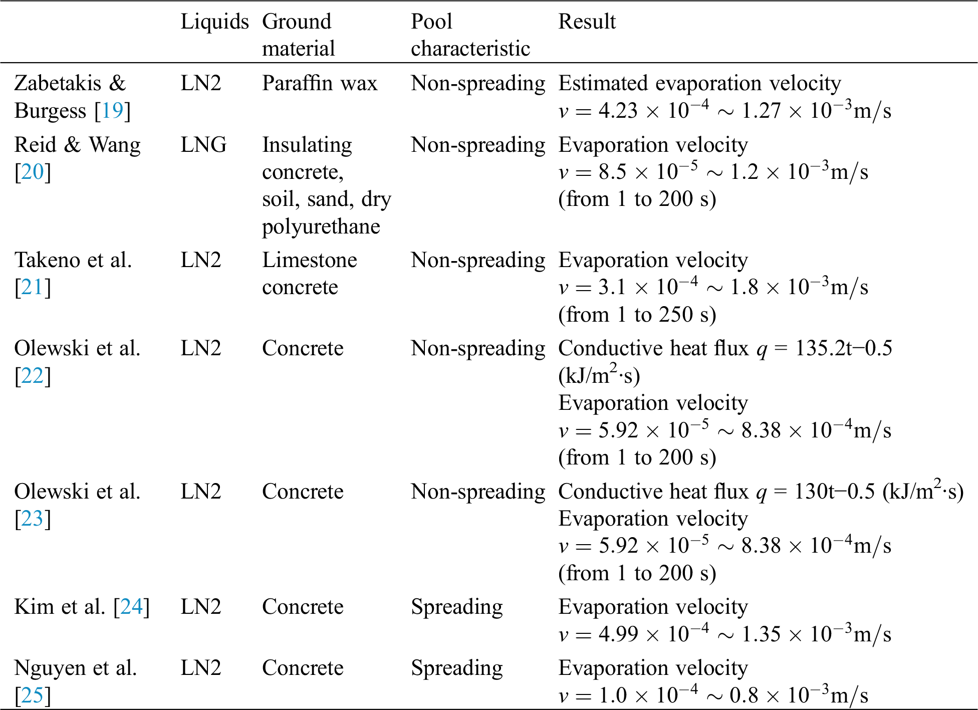
The existing experiments of pool boiling of LNG or other cryogenic liquid on ground are shown in Tab. 1. Reid et al. [20] measured and interpreted the boiling rate of LNG on the material that can be used as the bottom plate of the dam of LNG facilities; Takeno et al. [21] measured the evaporation rate of liquid hydrogen and liquid oxygen under laboratory conditions by simulating the ground with concrete, dry sand layer and wet sand layer; Olewski et al. [22,23] have studied the influence of different heat transfer mechanisms on the evaporation rate of cryogenic liquids through a series of small, controllable, instrumented liquid nitrogen experiments, simultaneous interpreting the evaporation rate of liquid nitrogen; Kim et al. [24] measured the evaporation rate of liquid pool dispersion by continuously releasing liquid nitrogen onto the unconfined concrete ground; Nguyen et al. [25] Spilled cryogenic liquid onto the boundless ground at a limited flow rate to evaluate the effect of the outflow rate on the evaporation rate of the radial dispersion pool.
Table 1: Comparison of experimental results
Compared with the large-scale field experiment, the cost of wind tunnel experiment is reduced and the reliability is improved. It can carry out the simulation experiment of related stations and climatic conditions, and expand the scope of field experiment. In particular, in order to control the evaporation rate of LNG pool, an auxiliary heating system can be installed at the bottom of the leakage pool, and the evaporation rate can be measured by a mass balance; at the same time, sensors can be arranged at the downstream of the wind tunnel to collect the temperature, concentration and speed parameters of the dispersion gas; LNG is flammable, so the wind tunnel should adopt the blast design, and the power system is located in the upstream of the wind tunnel; the sensor layout in the wind tunnel should ensure that the blocking rate control section area is less than 5% [8]; through the wind speed regulation of the wind tunnel, the analysis of the dispersion process under different atmospheric wind speed conditions can be realized; if you want to simulate the influence of different ground temperature conditions on the dispersion behavior of LNG pool, a temperature control heating system can be added; the LNG filling and discharging system can be designed to modeling the dispersion simulation experiments with different leakage rates.
2.2 Numerical Simulation Study
According to the description of the experimental study in the previous section, with the continuous improvement of the wind tunnel experimental platform, the method of neglecting most environmental factors (such as wind direction, wind speed and ground temperature) has been gradually improved, and the influence of station structure layout, terrain and obstacle conditions on LNG leakage and dispersion can be studied by designing large experimental sections. However, the leakage of LNG occurs in an open environment, and it is a state of free dispersion. At the same time, different types of LNG container rupture will also cause errors in the research results [26]. In order to reduce the error and make the result closer to the real situation, the numerical simulation method is used to study the LNG dispersion. Markowski [27] considers the uncertain factors and applies the traditional approach and fuzzy logic support to the case study of LNG leakage. The results illustrated the sensitivity of the risk ranking matrix to the risk correction index and proved the advantages of the fuzzy risk ranking methodology in relation to the traditional approach. Numerical simulation methods can be divided into integral models, shallow-layer models and computational fluid dynamics (CFD) models [13].
The integral model calculates diffusion and vaporization of the pool by mass conservation and energy conservation [28]. Different integral models use different simplification conditions, such as, pool spread rate (whether the pool thickness is uniform), heat transfer models (heat conduction, or thermal convection), type of spill (continuous or instantaneous) and solution method (discretion method). Webber et al. [29] briefly introduced the existing 16 integral models for LNG pool expansion, the most widely used is PHAST software developed by Det Norske Veritas (DNV), which has been affirmed by many cases [30]. Basha et al. [31] proposed a source term model to estimate the expansion rate of the onshore unconfined LNG pool. The model takes into account the change of boiling mixture composition, the change of thermodynamic properties caused by preferential boiling in liquid mixture and the effect of boiling mode on heat transfer. The model is compared with the one-dimensional heat conduction gravity inertial pool diffusion model. The advantage of the integral model is that the calculation speed is fast, while the disadvantage is that it is assumed that the liquid has perfect contact with the ground. Therefore, the liquid and the ground use the same constant temperature, and the ground temperature is equal to the boiling point of the liquid, thereby converting complex thermodynamic problems into one-dimensional heat conduction problems. By calculating the one-dimensional Fourier heat conduction equation for the calculation of heat flux density and the estimation of the liquid gasification rate of the pool. Although this method is fast, it obviously cannot fully comply with the actual situation. For example, if the pool fluid encounters an obstacle during the spreading process, or when the LNG spread under water surface, the method cannot be applied and needs to be corrected. Based on this, Wang [32] considered using differential method, combined with liquid dispersion model and heat transfer model, established a prediction model for the maximum LNG evaporation rate and the change of evaporation rate with time. Taking a 5 m3 cylindrical LNG tank as an example, the LNG leakage rate, evaporation rate, the variation of LNG pool propagation radius, and the changes of low-temperature liquid mass and LNG pool thickness were calculated.
The shallow-layer models assume that the transport properties of the fluid only change in the transverse direction, while the vertical direction is unchanged [33], typically the FLACS software developed by Gexcon. The shallow model uses the approximate value principle of the shallow theory, assuming that in the main body of the gas cloud, the pressure distribution can be described by the hydrostatics theory, and only at the front edge of the gas cloud can special situations occur; the mass exchange between the gas cloud and the surrounding air can be shown by the entrainment velocity; by adding some additional terms to the momentum equation, the heavy gas expansion on the complex terrain can be considered San [34,35]. However, under practical conditions, cryogenic liquids (for example, LNG with a boiling point of ≤162°C) exhibit a sharp boiling phenomenon when leaking to the ground, and cannot be directly simplified into a two-dimensional fluid motion. The liquid may be in a state of among nucleate boiling regime and membrane boiling regime (as is shown in Fig. 2), there is a considerable amount of air bubbles at the interface of liquid and ground, which in turn severely changes the contact conditions of the cryogenic liquid with the ground to change the heat transfer rate. In addition, the generation of bubbles may also change the diffusion behavior of the pool [36].
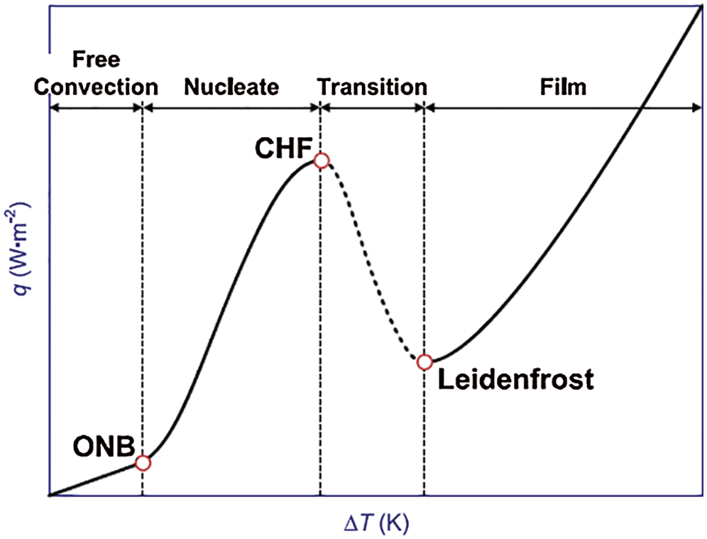
Figure 2: Typical boiling heat transfer curve (ONB—Onset of Nucleate Boiling; CHF—Critical Heat Flux)
Fem3 CFD model developed by the University of Arkansas is the first one that can simulate the liquid diffusion process. Although it is not the first CFD model, it is the first three-dimensional calculation model, and it can accurately model. Its results have been verified by previous field tests, which is of milestone significance, but the solution speed is slow [37]. In order to improve the calculation speed, the model needs to be simplified. For example, Liu et al. [38] used FLUENT software for cryogenic liquid boiling diffusion, but the effect of surface roughness is neglected. Due to lack of droplet size data, when Ahammad et al. [39] were modeling cryonic pool boiling with ANYSY CFX, there was a certain gap between the model and the experimental data. Ichard et al. [40] calculated the diffusion and evaporation of liquid hydrogen on the ground using the pool model in the CFD software FLACS, and also considered the partial condensation or freezing of oxygen and nitrogen. The simulation results of the new model were compared with the selected experiments in the health and safety laboratory (HSL). Prankul [41] proposed a pool model that can accurately predict the dispersion and evaporation of cryogenic liquids on different ground surfaces, taking into account the influence of obstacles on liquid dispersion and evaporation, and applied it to the FLACS fluid simulation software, which was compared with NASA experiments, with high accuracy. Arntzen [42] proposed the LAUV calculation model to calculate the dispersion and evaporation of cryogenic liquid on different ground and water surfaces. The model considered the influence of water surface icing on evaporation rate, and applied it to CFD software, and the simulation results were in good agreement with the actual situation.
Since the main component of LNG is methane, it is lighter than air at room temperature. However, because of the low boiling point of LNG, its vapor is denser than air (about 1.5 times compared with air). Therefore, the LNG vapor cloud dispersion has the characteristics of heavy gas dispersion, which satisfies the heavy gas diffusion process(as shown in Fig. 3) [43–46]: (1) Gravity sedimentation: at the beginning of the leakage, after the initial momentum disappears, the gravity makes the gas cloud fall to the ground and expand along the surface. Because the cloud density is higher than the air density, there is a concave phenomenon, which causes the cloud radial size to increase and the height to decrease. At this time, the turbulent diffusion caused by gravity dominates; (2) Cloud heating: due to the extremely low temperature of LNG, there is a huge temperature difference between the leaked LNG and the surrounding air. The leaked LNG will continuously absorb heat from the surrounding air and slowly heat up, forming a low-temperature cloud. What dominates is the convective turbulence caused by temperature gradient; (3) Air entrainment: Namely, air entrainment, which is divided into top air entrainment and side air entrainment. In the later stage of diffusion, the heavy gas cloud is continuously mixed with the surrounding air while diffusing, and the density of natural gas is continuously reduced in the cloud. In addition, with the effect of temperature rising, its density is also gradually reduced, and the final density is basically the same with the air, in other words, the dilution process of the cloud. At this time, the cloud diffusion is mainly controlled by atmospheric turbulence; (4) Passive diffusion: With the dilution of the cloud, the ratio of kinetic energy to potential energy, i.e., Richard’s number, gradually decreases. When the current value is less than the critical value, it can be considered that there is no heavy gas diffusion effect, and the diffusion process is transformed into atmospheric diffusion. At this time, atmospheric turbulence will play a leading role in the diffusion of the cloud.
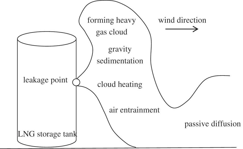
Figure 3: Schematic diagram of LNG leakage and diffusion from storage tank
In European countries and the United States, NFPA 59A developed by the National Fire Protection Association is generally had adopted as the standard of engineering design for LNG storage sites [47]. The standard stipulates that LNG storage enterprises must predict the maximum impact range after leakage (the ground concentration is greater than 1/2 minimum combustion limit) and take corresponding measures to minimize the scope of influence. The research on heavy gas dispersion mainly includes: experimental research and numerical simulation research.
Field experiments aim at analyzing and verifying the model, at the same time, testing the effects of environmental conditions. In foreign countries, the early field experiments were mainly the dispersion experiments of small-scale LNG offshore. The large-scale field’s experiments reached a peak around the 1980s, and a series of experiments on the diffusion of heavy gas and liquefied gas were carried out. The experimental medium includes a mixed gas of LNG, LPG (liquefied petroleum gas), liquid ammonia, freon and nitrogen, hydrogen fluoride and sulfur dioxide. Large-scale LNG field experiments are shown in Tab. 2.
Table 2: Large LNG leakage test
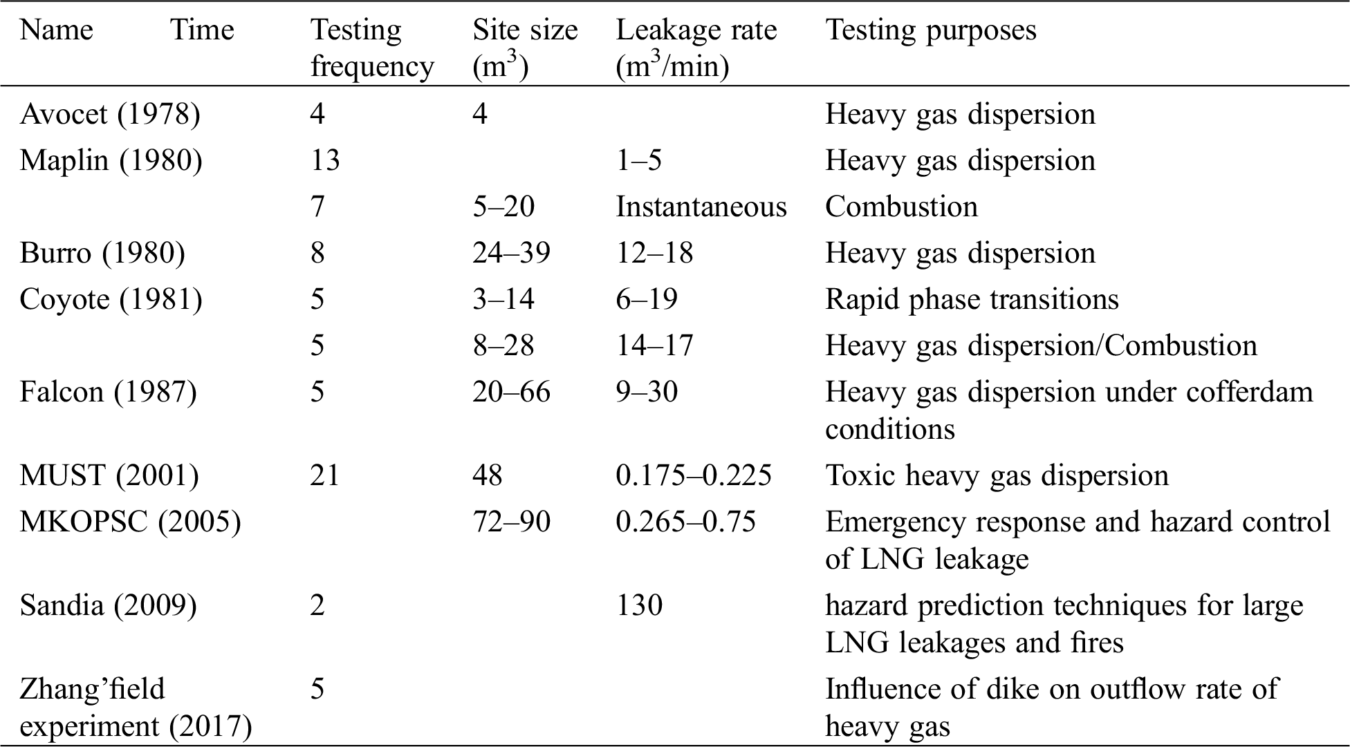
Maplin sands experiment: shell company has carried out 14 LNG and LPG and leakage tests. The main purpose of this test is to collect and leak diffusion as well as fire heat radiation data [48]. It is found that the characteristics of leakage diffusion are not only related to the leakage rate, but also to the leakage mode [49]. Burro experiment: the U.S. Department of energy and the gas research institute let Lawrence Livermore National Laboratory carry out eight LNG leakage tests in the China Lake Naval Weapons Center in California [50]. Because of the number of measuring instruments and the accuracy of instruments, this experiment has obtained more valuable LNG leakage and diffusion test data. Coyote experiment: Lawrence Livermore National Laboratory is on the site of burro series of experiments. In this experiment, more meteorological and concentration measuring instruments are arranged to systematically study the rapid phase change reaction of LNG, the ignition characteristics of large area gas cloud and collect more gas cloud diffusion data [51]. Falcon experiment: Lawrence Livermore National Laboratory has carried out five large-scale LNG leakage tests, which leak LNG into a pool in a 44 m × 88 m × 10 m solid enclosure structure, in order to evaluate the prevention effect of cofferdam on LNG tank leakage and diffusion and provide a numerical set for the verification of leakage and diffusion model in complex terrain [8]. MKOPSC experiment: Since 2005 a series of LNG leakage experiments has been carried out with LNG training props at the BFTF by the MKOPSC to study key parameters of vapor dispersion modeling and to collect experimental data for model validation, to investigate the emergency response and hazard control of LNG leakage [52,53]. The Mock Urban Setting Trial (MUST) experiment: It described herein was designed to provide insight into the instantaneous dispersion of a tracer through a large array of building-like obstacles. It is believed that the present field experiment is a logical addition to the series of previous experimental works on mean field dispersion in array plumes and on the study of concentration fluctuations in open-terrain plumes [54]. Sandia experiment: Congress funded the Department of Energy (DOE) in 2008 to conduct a series of laboratory and large-scale LNG pool fire experiments at Sandia National Laboratories (Sandia) in Albuquerque, New Mexico to improve the understanding of flame height, smoke production, and burn rate and therefore the physics and hazards of large LNG leakages and fires [55]. Zhang’ field experiment: In 2017 Zhang set up several groups of control experiments on laboratory scale and field scale to study the influence of factors such as the configuration of dike and storage tank, and the material of dike on LNG leakage outflow rate. The experimental results show that the outflow rate of LNG is slightly lower than that of water in large-scale field experiments. The analysis results show that this phenomenon may be caused by the volatilization of LNG in the process of liquid outflow [56].
In the case of large manpower and financial resources support during the field test period, wind tunnel experiments research can be used to reduce the scale of experiment and make the experiment more controllable. The simulation results can be used to check the mathematical model and to make it more reliable [57,58]. As a result, this type of method has been adopted all around the world, providing a source of data for the establishment of mathematical models. Krogstad et al. [59] Simulated the continuous diffusion rule of LNG heavy gas in wind tunnel. By studying the influence of rectangular shelter on the diffusion of heavy gas, they found that the shelter seriously affected the shape of diffusion cloud plume of heavy gas, and would form vortex on the leeward side of the shelter and the concentration value of gas cloud was low. With the help of its largest ultra-low wind tunnel in the world, the University of Arkansas dangerous chemicals research center (CHRC) has been studying LNG leakage and diffusion, investigating the leakage and diffusion behavior in the case of ground obstacles and providing a validation data set for the mathematical model [60]. The main purpose of Ba Hamburg wind tunnel test in Germany is to study the influence of upwind, downwind, circular cofferdam and inclined surface on LNG leakage and diffusion. The ba-tno wind tunnel test in the Netherlands clearly demonstrates the interaction scenarios of various ground obstacles and clouds, and reveals the influence of different ground obstacles on the diffusion [61]. The data from the two experiments are often used to evaluate the mathematical model of heavy gas dispersion. Neff [62] also simulated the smoke plume dispersion of heavy gas through wind tunnel experiment, and the selected leakage source was the ground circular surface source, and the test data results were in good agreement with the field experiment data. Robert et al. [63] studied the effect of ground roughness on the dispersion of continuous source and compared it with the numerical model for calculating the dispersion of heavy gas on flat surface. The experiment results show that when the roughness reaches 0.5 m in the numerical model, it is in good agreement with the wind tunnel experiment results. It is also shown that the interaction between the wind tunnel experiment and the numerical simulation will occur when the roughness is large, which directly affects the comparison results between the wind tunnel experiment and the numerical simulation.
3.2 Numerical Simulation Study
When LNG leaks from the storage tank, the state of the leakage source (including continuous or instantaneous leakage, leakage rate, etc.) has an important impact on the dispersion behavior of LNG vapor. When using numerical simulation method to simulate LNG diffusion, the calculation result of LNG leakage source is the input of its vapor dispersion calculation process. Therefore, the accuracy of source calculation greatly affects the accuracy of dispersion process simulation. So it is necessary to establish a scientific and reasonable calculation model of LNG leakage source.
Instantaneous leakage model: assuming that the LNG storage tank is completely invalid under the damage of human or natural disasters, the LNG stored in the tank is completely poured out in an instant, forming the instantaneous leakage source. This kind of hypothetical instantaneous leakage is unlikely to be realized in reality, because it is difficult to break through the LNG storage tank construction technology, so the instantaneous leakage model is often used to evaluate the maximum impact range of LNG leakage and dispersion risk.
Continuous leakage model: When the leakage area of LNG storage tank is far less than the LNG liquid level area in the tank, the leaked LNG will not cause the liquid level in the tank to drop significantly. Generally, the continuous leakage model is used to simulate the leakage of cutting pieces or pipelines of LNG storage tank; when the leakage diameter of LNG storage tank is large, the leakage of LNG will not lead to the obvious drop of liquid level in the tank. At this time, the leakage source strength will change with the change of liquid level height and pressure in the tank.
3.2.2 LNG Vapor Dispersion Model Research
Based on the experimental data, mathematical methods are used to describe the dispersion of heavy gas. The models include: BM model, integral model and CFD model.
The BM model BM model (also called phenomenological model and nomogram model) is a series of computational charts drawn by Britter et al. [64] based on a large number of experimental data on continuous and instantaneous venting of heavy gases. This method has some characteristics of easy calculation, and the results of some experiments can be particularly well matched. However, the disadvantage is poor extensibility of the graphical method has, and this method is not suitable for the injection or two-phase release.
The integral model mainly considers the gravity-driven flow, the air escaping process and the advection of the wind field to the heavy gas. It can simulate both the steady-state and transient problems. The representative models are HEGADAS [65], DEGADIS [66], SLAB [67], etc. This type of model can be used to describe the general characteristics of the gas cloud, such as the average cloud radius, the average cloud height and the average cloud temperature, etc., regardless of its spatial details. This method is especially suitable for hazard evaluation, and the results have become an important part of emergency counseling, emergency response and other decisions. Liu et al. [68] used an improved integral model to simulate LNG leakage vapor dispersion, which took only a few seconds and could be visualized on Google Earth; Vílchez et al. [69] introduced a safe dispersion coefficient based on the DEGADIS model to improve forecast accuracy.
Compared with the integral model, the CFD model can better reflect the influence of obstacles and complex terrain on the flow field and diffusion process, and has been widely used to simulate the transportation and dispersion process of heavy gas. Fiates et al. [70] used the open source computational fluid dynamics software Open FOAM to simulate the LNG and CO2 vapor dispersion processes, and compared the results with FLACS software; Mishra [71] used ANSYS software to analyze the concentration distribution of iso-citrate after downwind conditions. These studies show that the CFD model has good simulation performance for the heavy gas vapor dispersion process. However, how to measure mesh quality of the CFD model, or how to set boundary conditions, or chose which turbulence model affect the accuracy of the simulation results. Liu et al. [72] proposed a model of dispersed release time by giving relevant theories and existing experimental data. When setting the initial conditions of calculation, a new method of DPM model is proposed to obtain the gas concentration and temperature change characteristics of the gas cloud through numerical simulation of the process of initial leakage and turbulent dispersion, and analyze and demonstrate these phenomena.
3.2.3 Study on the Selection of Turbulence Model
Generally, the cloud dispersion of heavy gas occurs in the boundary layer of the atmosphere, especially close to the bottom of the ground, that is, the near-surface layer. The core problem in atmospheric boundary layer research is the turbulence problem. The turbulence models include Reynolds Averaged Navier-Stokes (RANS) model, Large Eddy Simulation (LES) model, and Direct Numerical Simulation (DNS) model [73].
In practical engineering applications of heavy gas dispersion, the general concern is the mean value of flow, ignoring the details of turbulence, so most of the RANS method is used. Even so, there is still no uniform standard for the choice of turbulence models. Cheng et al. [74] found that the RNG k-ε model is more accurate than the standard k-ε model when simulating water curtain blocking ammonia diffusion; Xing et al. [75] found standard k-ε model and SST k-ω model is suitable for CO2 dispersion compared with the experimental data, while the results of the RNG k-ε model are not ideal; Dong et al. [76] performed the standard k-ε model, the Realizable k-ε model, the standard k-ω model, and the SST k-ω model, and the comparison shows that the standard k-ε model and the SST k-ω model have higher accuracy when performing indoor SF6 leakage vapor dispersion simulation. Existing studies in the LNG dispersion simulation usually select the turbulence model directly. For example, Sun et al. [77] used the LES model for LNG pool fire radiation simulation; Sklavounos et al. [78] chose the standard k-ε model; Zhang et al. [79] chose the Realizable k-ε model for the diffusion of LNG jet vapor clouds.
It can be seen from the above that researchers have done a lot of research on LNG leakage and dispersion, especially under the coupling effect of different influencing factors, using CFD to simulate the LNG leakage and dispersion evolution process, vapor cloud change shape, influence area, explosion risk range, etc. For the study of large LNG storage tank leakage and dispersion, the numerical simulation method has the advantages of high precision and strong operability. It cannot only effectively expand the theoretical research and experimental research results, but also carry out the research on LNG leakage and dispersion under complex working conditions. At present, although the research on the influencing factors of LNG leakage has made some progress, the research on the specific influence mechanism of jet shape, pool expansion and vapor cloud dispersion after continuous leakage of large LNG storage tank is still in the initial stage. This is due to the large structure size of LNG storage tank, and the wind field around the tank has the characteristics of circumfluence, backflow and stagnant flow. The influence of many factors on the leakage and dispersion process (jet length, liquid pool area, hazard range, etc.) needs to be further studied.
Due to the large consumption of manpower, material and financial resources in the field experiment, the external environmental changes are complex, and it is difficult to monitor in some cases, while it is difficult to achieve low wind speed and low Reynolds number in wind tunnel experiment. Therefore, the research on LNG leakage and dispersion mainly focuses on theoretical analysis. With the development of computer technology, CFD numerical simulation method is more and more popular. This paper summarizes the influence of ground conditions on LNG leakage and dispersion and the difference between ground and water surface leakage and dispersion of LNG, summarizes the field and wind tunnel experiment on LNG leakage and dispersion, and analyzes the research methods and mathematical models of spreading of pool and LNG vapor dispersion, hoping to provide guidance for accident prevention.
In the future research work, we should strengthen the combination of experimental research and numerical simulation, so that the two can complement each other, in order to provide technical support for the future research on large-scale LNG leakage and dispersion:
(1) More pool expansion/heavy gas dispersion experiments, especially when there is a strong change in the source of the leakage, there may be two-phase jets, flash atomization, etc. Or the case of moving the source of the leak.
(2) More comprehensive consideration of factors affecting the expansion of the pool liquid / heavy gas dispersion, such as air humidity, solar radiation, wind speed and direction, ground roughness.
(3) The influence of different obstacles and obstacles of different heights on the diffusion of heavy gas, the morphological changes and diffusion mechanism after encountering obstacles in the process of heavy gas diffusion.
Acknowledgement: This work is supported by Nanchong Science and Technology Bureau Project under Grant No. 18SXHZ0021.
Funding Statement: This work is supported by Nanchong Science and Technology Bureau Project under Grant No. 18SXHZ0021, initials of author: DJY, URLs to sponsors’ websites: http://kjj.nanchong.gov.cn/.
Conflicts of Interest: The authors declare that they have no conflicts of interest to report regarding the present study.
References
1. Fang, X. Y. (2019). Global LNG market development prospect and its geopolitical impact. Economic Forum, 8, 87–93.
2. Zhu, G., Guo, X., Yi, Y., Tan, W., Ji, C. (2020). Experiment and simulation research of evolution process for LNG leakage and diffusion. Journal of Loss Prevention in the Process Industries, 64, 104041. DOI 10.1016/j.jlp.2019.104041.
3. Wang, L., Hua, M., He, B., Ye, C., Pan, X. (2015). Analysis of the influential factors on the risks of LNG storage tank leakage. Journal of Safety and Environment, 15(2), 35–37.
4. Chen, B., Liu, J., Zhou, N., Chen, L. (2018). The effect of ground conditions on the leakage diffusion of LNG. Journal of Industrial Safety and Environmental Protection, 44(11), 1–5.
5. Luketa-Hanlin, A. (2006). A review of large-scale LNG spills: Experiments and modeling. Journal of Hazardous Materials, 132(2-3), 119–140. DOI 10.1016/j.jhazmat.2005.10.008.
6. Lin, X., Yu, G., Wei, L., Chen, X. (2014). Comparative study of LNG dispersion on water and ground. Journal of Safety Science and Technology, 10(8), 86–90.
7. Cao, W., Lu, X., Gu, A., Lin, W., Shi, Y. (2006). LNG receiving terminal and its correlative techniques, 26(1), 112–115.
8. Giannissi, S. G., Venetsanos, A. G., Markatos, N., Bartzis, J. G. (2013). Numerical simulation of LNG dispersion under two-phase release conditions. Journal of Loss Prevention in the Process Industries, 26(1), 245–254. DOI 10.1016/j.jlp.2012.11.010.
9. Rana, M. A., Guo, Y., Mannan, M. S. (2010). Use of water spray curtain to disperse LNG vapor clouds. Journal of Loss Prevention in the Process Industries, 23(1), 77–88. DOI 10.1016/j.jlp.2009.06.003.
10. Basha, O., Olewski, T., Véchot, L., Castier, M., Mannan, S. (2014). Modeling of pool spreading of LNG on land. Journal of Loss Prevention in the Process Industries, 30, 307–314. DOI 10.1016/j.jlp.2014.04.012.
11. Reniers, G., Amyotte, P. (2012). Prevention in the chemical and process industries: Future directions. Journal of Loss Prevention in the Process Industries, 25(1), 227–231. DOI 10.1016/j.jlp.2011.06.016.
12. Saleem, A., Farooq, S., Karimi, I. A., Banerjee, R. (2018). A CFD simulation study of boiling mechanism and BOG generation in a full-scale LNG storage tank. Computers & Chemical Engineering, 115, 112–120. DOI 10.1016/j.compchemeng.2018.04.003.
13. Gopalaswami, N., Kakosimos, K., Zhang, B., Liu, Y., Mentzer, R. et al. (2017). Experimental and numerical study of liquefied natural gas (LNG) pool spreading and vaporization on water. Journal of Hazardous Materials, 334(15), 244–255. DOI 10.1016/j.jhazmat.2017.04.025.
14. Raj, P. K. (2007). LNG fires: A review of experimental results, models and hazard prediction challenges. Journal of Hazardous Materials, 140(3), 444–464. DOI 10.1016/j.jhazmat.2006.10.029.
15. Hu, L., Shuai, L., Ris, J. L. D., Long, W. (2013). A new mathematical quantification of wind-blown flame tilt angle of hydrocarbon pool fires with a new global correlation model. Fuel, 106, 730–736. DOI 10.1016/j.fuel.2012.10.075.
16. Zhang, B., Laboureur, D. M., Liu, Y., Gopalaswami, N., Mannan, M. S. (2018). Experimental study of a liquefied natural gas pool fire on land in the field. Industrial & Engineering Chemistry Research, 57(42), 14297–14306. DOI 10.1021/acs.iecr.8b02087.
17. Vilchez, J. A., Villafane, D., Casal, J. (2013). A dispersion safety factor for LNG vapor clouds. Journal of Hazardous Materials, 246-247, 181–188. DOI 10.1016/j.jhazmat.2012.11.045.
18. Verfondern, K., Dienhart, B. (2007). Pool spreading and vaporization of liquid hydrogen. International Journal of Hydrogen Energy, 32(13), 2106–2117. DOI 10.1016/j.ijhydene.2007.04.015.
19. Zabetakis, M. G., Burgess, D. S. (1961). Research on hazards associated with production and handling of liquid hydrogen. [Fire hazards and formation of shock-sensitive condensed mixtures]. Washington, DC: Bureau of Mines.
20. Reid, R., Wang, R. (1978). The boiling rates of LNG on typical dike floor materials. Cryogenics, 18(7), 401–404. DOI 10.1016/0011-2275(78)90033-4.
21. Takeno, K., Ichinose, T., Hyodo, Y., Nakamura, H. (1994). Evaporation rates of liquid hydrogen and liquid oxygen spilled onto the ground. Journal of Loss Prevention in the Process Industries, 7(5), 425–431. DOI 10.1016/0950-4230(94)80061-8.
22. Olewski, T., V\xE9chot, L., Mannan, S. (2013). Study of the vaporization rate of liquid nitrogen by small-and medium-scale experiments. LP2013-14TH Symposium on loss prevention and safety promotion in the process industries, Chemical Engineering Transactions, 133–138.
23. Olewski, T., Mannan, S., Véchot, L. (2015). Validation of liquid nitrogen vaporisation rate by small scale experiments and analysis of the conductive heat flux from the concrete. Journal of Loss Prevention in the Process Industries, 35, 277–282. DOI 10.1016/j.jlp.2014.08.008.
24. Kim, M., Nguyen, D., Choi, B. (2016). Experimental study of the evaporation of spreading liquid nitrogen. Journal of Loss Prevention in the Process Industries, 39, 68–73. DOI 10.1016/j.jlp.2015.11.018.
25. Nguyen, L. D., Kim, M., Choi, B. (2017). An experimental investigation of the evaporation of cryogenic-liquid-pool spreading on concrete ground. Applied Thermal Engineering, 123, 196–204. DOI 10.1016/j.applthermaleng.2017.05.094.
26. Siuta, D., Markowski, A. S., Mannan, M. S. (2013). Uncertainty techniques in liquefied natural gas (LNG) dispersion calculations. Journal of Loss Prevention in the Process Industries, 26(3), 418–426. DOI 10.1016/j.jlp.2012.07.020.
27. Markowski, A. S., Siuta, D. (2018). Fuzzy logic approach for identifying representative accident scenarios. Journal of Loss Prevention in the Process Industries, 56, 414–423. DOI 10.1016/j.jlp.2018.10.003.
28. Sun, B., Guo, K. (2010). Safety exclusive distance of LNG dense gas dispersion and its influencing factors. Natural Gas Industry, 30(7), 110–113.
29. Webber, D., Gant, S., Ivings, M., Jagger, S. (2009). LNG source term models for hazard analysis: a review of the state-of-the-art and an approach to model assessment. Derbyshire: Health and Safety Executive.
30. Witlox, H., Harperm, M., Pitblado, R. (2013). Validation of PHAST dispersion model as required for USA LNG siting applications. 14th EFCE International Conference on Loss Prevention and Safety, 31, 49–54.
31. Basha, O., Yi, L., Castier, M., Olewski, T., Vechot, L. (2013). Modelling of LNG pool spreading on land with included vapour-liquid equilibrium and different boiling regimes. Chemical Engineering Transactions, 31, 43–48.
32. Wang, L., He, B., Pan, X. (2014). Calculation of evaporation rate of leaked LNG on the ground. Oil & Gas Storage and Transportation, 33(6), 648–652.
33. Webber, D., Ivings, M. (2010). Modelling bund overtopping using shallow water theory. Journal of Loss Prevention in the Process Industries, 23(5), 662–667. DOI 10.1016/j.jlp.2010.07.002.
34. Hankin, R. K. S. (2003). Shallow layer simulation of heavy gas released on a slope in a calm ambient. Part I. Continuous releases. Journal of Hazardous Materials, 103(3), 205–215. DOI 10.1016/S0304-3894(03)00224-3.
35. Hankin, R. K. S. (2003). Shallow layer simulation of heavy gas released on a slope in a calm ambient. Part II. Instantaneous releases. Journal of Hazardous Materials, 103(3), 205–215. DOI 10.1016/S0304-3894(03)00224-3.
36. Fay, J. (2007). Spread of large LNG pools on the sea. Journal of Hazardous Materials, 140(3), 541–551. DOI 10.1016/j.jhazmat.2006.10.024.
37. Meroney, R. N. (2004). Wind tunnel and numerical simulation of pollution dispersion: A hybrid approach Colorado. Fort Collins, CO: State University.
38. Liu, Y., Olewski, T., Véchot, L. N. (2015). Modeling of a cryogenic liquid pool boiling by CFD simulation. Journal of Loss Prevention in the Process Industries, 35, 125–134. DOI 10.1016/j.jlp.2015.04.006.
39. Ahammad, M., Quraishy, S., Olewski, T., Véchot, L. (2017). Small-scale field spill experiments of liquid nitrogen, oxygen and their mixture on concrete surface. Journal of Loss Prevention in the Process Industries, 50, 112–120. DOI 10.1016/j.jlp.2017.09.009.
40. Ichard, M., Hansen, O. R., Middha, P., Willoughby, D. (2012). CFD computations of liquid hydrogen releases. International Journal of Hydrogen Energy, 37(22), 17380–17389. DOI 10.1016/j.ijhydene.2012.05.145.
41. Middha, P., Ichard, M., Arntzen, B. R. J. (2011). Validation of CFD modelling of LH2 spread and evaporation against large-scale spill experiments. International Journal of Hydrogen Energy, 36(3), 2620–2627. DOI 10.1016/j.ijhydene.2010.03.122.
42. Dienhart, K. V. (1997). Experimental and theoretical investigation of liquid hydrogen pool spreading and vaporization. International Journal of Hydrogen Energy, 22(7), 649–660. DOI 10.1016/S0360-3199(96)00204-2.
43. Markiewicz, M. T. (2010). Mathematical modeling of the heavy gas atmospheric dispersion over complex and obstructed terrain. Archives of Environmental Protection, 36, 81–94.
44. Mohan, M., Panwar, T. S., Singh, M. P. (1995). Development of dense gas dispersion model for emergency preparedness. Atmospheric Environment, 29(16), 2075–2087. DOI 10.1016/1352-2310(94)00244-F.
45. Cormier, B. R., Qi, R., Yun, G. W., Zhang, Y., Mannan, M. S. (2009). Application of computational fluid dynamics for LNG vapor dispersion modeling: A study of key parameters. Journal of Loss Prevention in the Process Industries, 22(3), 332–352. DOI 10.1016/j.jlp.2008.12.004.
46. Qi, R., Ng, D., Waldram, S. P., Mannan, M. S. (2010). Uncertainties in modeling LNG vapor dispersion with CFD codes. AIChE Spring Meeting and Global Congress on Process Safety.
47. NFPA 59A, N. (2009). Standard for the production, storage, and handling of liquefied natural gas (LNG). Quincy: NFPA.
48. Hansen, O. R., Gavelli, F., Ichard, M., Davis, S. G. (2010). Validation of FLACS against experimental data sets from the model evaluation database for LNG vapor dispersion. Journal of Loss Prevention in the Process Industries, 23(6), 857–877. DOI 10.1016/j.jlp.2010.08.005.
49. Luketa-Hanlin, A. J. (2006). A review of large-scale LNG spills: Experiments and modeling. Journal of Hazardous Materials, 132(2-3), 119–140. DOI 10.1016/j.jhazmat.2005.10.008.
50. Sun, B., Utikar, R. P., Pareek, V. K., Guo, K. (2013). Computational fluid dynamics analysis of liquefied natural gas dispersion for risk assessment strategies. Journal of Loss Prevention in the Process Industries, 26(1), 117–128. DOI 10.1016/j.jlp.2012.10.002.
51. Huang, Q., Jiang, J. C. (2007). Comparisons for LNG dispersion models. Safety production science and technology in China, 3(5), 3–6.
52. Qi, R., Ng, D., Waldram, S. P., Mannan, M. S. (2010). Uncertainties in modeling LNG vapor dispersion with CFD Codes. 2010 AIChE Spring National Meeting, 6, 9–10.
53. Gopalaswami, N., Mentzer, R. A., Sam Mannan, M. (2015). Investigation of pool spreading and vaporization behavior in medium-scale LNG tests. Journal of Loss Prevention in the Process Industries, 35, 267–276. DOI 10.1016/j.jlp.2014.10.012.
54. Yee, E., Biltoft, C. A. (2004). Concentration fluctuation measurements in a plume dispersing through a regular array of obstacles. Boundary-Layer Meteorology, 111(3), 363–415. DOI 10.1023/B:BOUN.0000016496.83909.ee.
55. Blanchart, T., Helmick, P. (2010). The phoenix series large scale LNG pool fire experiments. Albuquerque: Sandia National Laboratories, vol. SAND2010-8676.
56. Zhang, B., Liu, Y., Zhu, W., Gopalaswami, N., Mannan, M. S. (2017). Experimental study of bund overtopping caused by a catastrophic failure of tanks. Industrial & Engineering Chemistry Research, 56(42), 12227–12235. DOI 10.1021/acs.iecr.7b02931.
57. Guo, X., Chen, S., Yan, X., Zhang, X., Yu, J. et al. (2018). Flow characteristics and dispersion during the leakage of high pressure CO2 from an industrial scale pipeline. International Journal of Greenhouse Gas Control, 73, 70–78. DOI 10.1016/j.ijggc.2018.04.002.
58. Briggs, G. A., Britter, R. E., Hanna, S. R., Havens, J. A., Robins, A. G. et al. (2001). Dense gas vertical diffusion over rough surfaces: results of wind-tunnel studies. Atmospheric Environment, 35(13), 2265–2284. DOI 10.1016/S1352-2310(00)00360-5.
59. Krogstad, P. A., Pettersen, R. M. (1986). Windtunnel modelling of a release of a heavy gas near a building. Atmospheric Environment (1967), 20(5), 867–878. DOI 10.1016/0004-6981(86)90271-4.
60. Chan, S. T. (1992). Numerical simulations of LNG vapor dispersion from a fenced storage area. Journal of Hazardous Materials, 30(2), 195–224. DOI 10.1016/0304-3894(92)85078-F.
61. Tauseef, S. M., Rashtchian, D., Abbasi, S. A. (2011). CFD-based simulation of dense gas dispersion in presence of obstacles. Journal of Loss Prevention in the Process Industries, 24(4), 371–376. DOI 10.1016/j.jlp.2011.01.014.
62. Neff, D. E. (1989). Physical modeling of heavy plume dispersion. Colorado State University. OSTI Identifier: 6678869.
63. Roberts, P. T., Hall, D. J. (1994). Wind-tunnel simulation. Boundary layer effects in dense gas dispersion experiments. Journal of Loss Prevention in the Process Industries, 7(2), 106–117. DOI 10.1016/0950-4230(94)80026-X.
64. Britter, R. E., McQuaid, J. (1989). Modelling dispersion from accidental releases. Air Pollution Modeling and Its Application VII, 7, 39–52.
65. Witlox, H. J. (1994). The HEGADAS model for ground-level heavy-gas dispersion—I. Steady-state model. Atmospheric Environment, 28(18), 2917–2932. DOI 10.1016/1352-2310(94)90340-9.
66. Spicer, T., Havens, J., Guinnup, D. (1989). User’s guide for the DEGADIS 2.1 dense gas dispersion model: US Environmental Protection Agency.
67. Ermak, D. L. (1990). User’s manual for SLAB: An atmospheric dispersion model for denser-than-air-releases. Lawrence Livermore National Lab., CA.
68. Liu, D., Wei, J. (2017). Modelling and simulation of continuous dense gas leakage for emergency response application. Journal of Loss Prevention in the Process Industries, 48, 14–20. DOI 10.1016/j.jlp.2017.03.026.
69. Vilchez, J. A., Villafane, D., Casal, J. (2013). A dispersion safety factor for LNG vapor clouds. Journal of Hazardous Materials, 246-247, 181–188. DOI 10.1016/j.jhazmat.2012.11.045.
70. Fiates, J., Santos, R. R. C., Neto, F. F., Francesconi, A. Z., Simoes, V. et al. (2016). An alternative CFD tool for gas dispersion modelling of heavy gas. Journal of Loss Prevention in the Process Industries, 44, 583–593. DOI 10.1016/j.jlp.2016.08.002.
71. Mishra, K. B. (2015). CFD model for large hazardous dense cloud spread predictions, with particular reference to Bhopal disaster. Atmospheric Environment, 117, 74–91. DOI 10.1016/j.atmosenv.2015.06.038.
72. Wei, T., Xiao, L., Liu, Y., Yu, B., Wang, Z. J. (2011). Modeling the two-phase cloud evolution from instantaneous flashing release using CFD. Journal of Loss Prevention in the Process Industries, 24(4), 420–425. DOI 10.1016/j.jlp.2011.03.003.
73. Ramponi, R., Blocken, B. (2012). CFD simulation of cross-ventilation for a generic isolated building: Impact of computational parameters. Building and Environment, 53, 34–48. DOI 10.1016/j.buildenv.2012.01.004.
74. Cheng, C., Tan, W., Liu, L. (2014). Numerical simulation of water curtain application for ammonia release dispersion. Journal of Loss Prevention in the Process Industries, 30, 105–112. DOI 10.1016/j.jlp.2014.05.003.
75. Xing, J., Liu, Z., Huang, P., Feng, C., Zhou, Y. et al. (2013). Experimental and numerical study of the dispersion of carbon dioxide plume. Journal of Hazardous Materials, 256-257, 40–48. DOI 10.1016/j.jhazmat.2013.03.066.
76. Dong, L., Zuo, H., Hu, L., Yang, B., Li, L. et al. (2017). Simulation of heavy gas dispersion in a large indoor space using CFD model. Journal of Loss Prevention in the Process Industries, 46, 1–12. DOI 10.1016/j.jlp.2017.01.012.
77. Sun, B., Guo, K., Pareek, V. K. (2017). Hazardous consequence dynamic simulation of LNG spill on water for ship-to-ship bunkering. Process Safety and Environmental Protection, 107, 402–413. DOI 10.1016/j.psep.2017.02.024.
78. Sklavounos, S., Rigas, F. (2006). Simulation of Coyote series trials—Part I: CFD estimation of non-isothermal LNG releases and comparison with box-model predictions. Chemical Engineering Science, 61(5), 1434–1443. DOI 10.1016/j.ces.2005.08.042.
79. Zhang, Q. X., Liang, D. (2016). Numerical simulations of LNG vapor dispersion from LNG jetting in different directions, 135, 316–321.
 | This work is licensed under a Creative Commons Attribution 4.0 International License, which permits unrestricted use, distribution, and reproduction in any medium, provided the original work is properly cited. |