DOI:10.32604/EE.2020.012381
| Energy Engineering DOI:10.32604/EE.2020.012381 | |
| Article |
Time-Domain Protection for Transmission Lines Connected to Wind Power Plant based on Model Matching and Hausdorff Distance
1Faculty of Land Resource Engineering, Kunming University of Science and Technology, Kunming, 650500, China
2Faculty of Electric Power Engineering, Kunming University of Science and Technology, Kunming, 650500, China
*Corresponding Author: Xiaohan Jiang. Email: jxhkunming@163.com
Received: 20 July 2020; Accepted: 21 August 2020
Abstract: The system impedance instability, high-order harmonics, and frequency offset are main fault characteristics of wind power system. Moreover, the measurement angle of faulty phase is affected by rotation speed frequency component, which causes traditional directional protections based on angle comparison between voltage and current to operate incorrectly. In this paper, a time-domain protection for connected to wind power plant based on model matching is proposed, which compares the calculated current and the measured current to identify internal faults and external faults. Under external faults, the calculated current and measured current waveform are quite similar because the protected transmission lines is equivalent to a lumped parameter model and the model itself is not damaged. However, the similarity of calculated current and measured current is quite low, due to destroyed integrity of model under internal faults. Additionally, Hausdorff distance is introduced to obtain the similarity of the calculated current and measured current. Since the proposed protection scheme is applied in time domain, it is independent from current frequency offsets of wind energy system, high-order harmonics, and system impedance variations. Comprehensive case studies are undertaken through Power Systems Computer Aided Design (PSCAD), while simulation results verify the accuracy and efficiency of the proposed approach in fault identification.
Keywords: Wind power plant; crowbar; time-domain protection; hausdorff distance; model matching
Renewable energy, such as wind and solar, is increasingly used for power generation because of the importance of sustainable energy supply and environmental protection in the economic and social development around the world [1–3]. In recent years, wind power generation has become the major role of renewable energy due to its cleanliness, short construction period and flexible installation scale [4–6]. The electricity generated by a large-scale wind energy station is usually sent to power grid by high voltage transmission lines, hence the correct protection action for transmission lines based on the fault characteristic of wind energy generation is essential for a safe and efficient use of renewable energy [7].
1. Thus far, some new researches on the development of modern power system protection and control are widely concerned [8–10]. Zheng et al. proposes a novel three-stage setting method of overcurrent relays, whose perform is well under multiple faults [8]. Kapoor et al. presents a protection technique based on HHT fault categorization, which only needs fault currents obtained at the first-end of transmission lines and is reliable to diverse faults [9]. Rezaei et al. proposes a novel genetic algorithm-based optimization technique, which drastically reduces the accumulative operation time of relays [10]. Tripathy et al. proposes a data processing method using wavelet transform and Fourier transform to accurately measure the electrical quantity of transmission lines, which forms a protection criterion based on action signal and suppression signal [11]. Ghorbani et al. proposes a method based on the combination of distance and differential protection [12]. In this method, fault resistance is calculated using active power calculation in both ends of the transmission line and its effects are deducted from calculated impedance by relay. Moreover, the response time of control system, about 10–20 ms [13], is much shorter than the action time of fast protection in the power system, about 60–90 ms. The electric potential in renewable energy station is not constant, so the traditional power frequency protection is difficult to adapt to the change of fault characteristics after connection of renewable energy. In addition, wind turbines based on crowbar circuit protection have low voltage ride through (LVRT) capability, so the impact of crowbar protection needs to be considered after a fault occurs [14,15]. Jayanthi et al. concludes from the simulation results that crowbar mitigates the high fault current during a fault in the grid [14].
2. The traditional protection is adversely affected by wind turbine control strategy which can vary the voltage and current after faults occur, hence numerous references studies the fault characteristics of transmission lines with wind turbine [16–18]. Suonan et al. analyses fault characteristics of current and voltage in wind farm, and current frequency offsets and high-order harmonics may lead to failure of differential protection based on power frequency [19]. Zheng et al. proposes a differential protection method based on structural similarity, which is superior to traditional differential protection and shows excellent performance in speed under faults [20]. Suonan et al. proposes a pilot protection based on phase segregated model recognition [21]. This novel protection principle is unnecessary to compensate the distribution capacitance current and has fast operation speed. Suonan et al. proposes a novel transmission line pilot protection principle based on integrated impedance and the criterion proposed is not affected by the capacitive current [22]. Wang et al. proposes a new pilot protection principle for transmission lines based on frequency-domain model recognition, which can detect the internal fault quickly and reliably, immune to the impacts of capacitive current and transition resistances [23]. Doubly-fed wind turbine is affected by the excitation system, which induces transient potential unstable under a fault, so Howard et al. analyses sequence component model of the asynchronous induction motor, and an accurate sequence network model of induction machines is derived to aid in short-circuit calculations in wind plants [24]. For the stability and protection of large-capacity offshore wind power systems, Biswas et al. investigates the impact of such TLs on distance relay and proposes a new fault detection [25]. The simulation shows that proposed scheme is correct under different wind speed. Amin et al. proposes a wind energy conversion system controller based on the synchronverter concept to solve the stability of an offshore wind power network [26]. Sadeghi, Dubey et al. propose two new and adaptive distance protection [27,28], and Sadeghi et al. designes an adaptive unit for distance relay using artificial neural networks. Dubey et al. proposes an adaptive relay setting for parallel lines. However, the impact of rotation speed frequency component on impedance measured by power frequency is not considered.
This paper proposes a protection method based on model matching and Hausdorff distance. The transmission line is equivalent to π model in this paper. Under external faults, the calculated current and measured current waveform are quite similar, because the protected transmission lines are equivalent to a lumped parameter model and the model itself is not damaged. However, the similarity of calculated current and measured current is quite low, due to destroyed integrity of model under internal faults. Moreover, Hausdorff distance is introduced to obtain the similarity of the calculated current and measured current. Simulation results verify the accuracy and efficiency of the proposed approach in fault identification. The main contributions of this manuscript can be summarized into the following four aspects:
•Action characteristics of traditional directional protection based on angle comparison of voltage are analysed, and it shows that measurement angle based on Fourier transform is affected by rotation speed frequency component, which causes traditional directional protections using angle comparison between voltage and current to operate incorrectly.
•A time-domain protection for connected to wind power plant based on model matching is proposed, which is not affected by rotation speed frequency component. Theoretically, it is not affected by the frequency deviation of current on wind power system, high-order harmonics, and impedance variations.
•The proposed method has a high accuracy and efficiency in fault identification, which is not affected by fault locations, fault types, and noise. It is suitable for field operation because the sampling frequency is lower.
•Hausdorff distance is introduced to obtain the similarity of the calculated current and measured current. Hausdorff distance can be carried out in a shorter time window and has a high efficiency in signal processing.
In this paper, Section 1 introduces related research in recent years. Section 2 analyses short-circuit current characteristics for doubly-fed induction generator (DFIG) and its influence on directional protection. Section 3 introduces time-domain protection based on model matching. Section 4 introduces Hausdorff distance. Section 5 establishes system model by PSCAD and provides simulation results, and Section 6 concludes the whole paper.
2 Analysis of Short-Circuit Current Characteristics for DFIG
2.1 Influence of Short-Circuit Current Characteristics for DFIG on Fourier Transform
Rotor side of DFIG is connected to grid through a converter, and stator side is directly connected to grid as shown in Fig. 1.
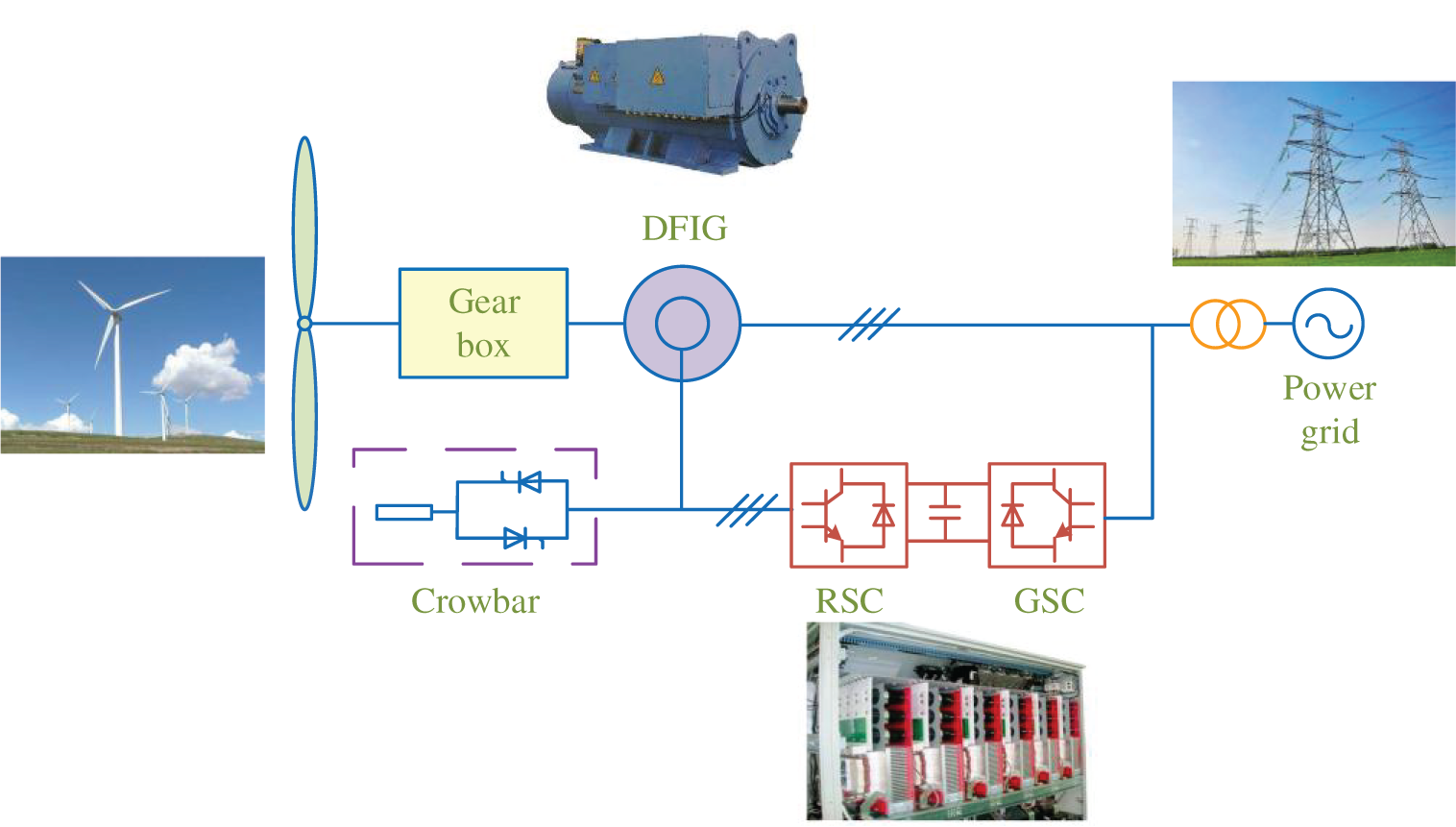
Figure 1: Structure diagram of DFIG with crowbar
During normal operation, DFIG is controlled by rotor converter for excitation. When power grid faults, voltage of DFIG terminal suddenly drops, and a large transient voltage and current will be induced in its rotor winding. Then, crowbar protection is put into rotor winding side to suppress transient current and protect converter from damage. At this time, three-phase short-circuit current can be expressed as [29]

where φc is initial phase angle of short-circuit current after crowbar protection; ω1 is synchronous speed; ωr is rotor speed; τsc and τrc are stator and rotor time decay constants considering crowbar protection action; respectively; Ac, Bc, and Cc are coefficients of each component for short-circuit current considering crowbar protection, which are related to motor parameters and voltage drop of motor terminal as shown in Appendix A.
In Eq. (1), it shows that short-circuit current provided by DFIG also contains attenuation speed frequency component, in addition to fundamental frequency component and the transient DC component. Before Fourier transform, the short-circuit current will be filtered by differential filtering to attenuate DC component. Thus, the short-circuit current calculated by Fourier contains only fundamental frequency component and attenuated rotation speed frequency component. In order to analyze its influence on Fourier transform, original signal is subjected to discrete Fourier transform to obtain cosine and sine coefficients for fundamental wave as [30]
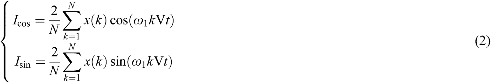
where N is number of sampling points in fundamental frequency period; Icos represents cosine coefficient of fundamental current after DFT; Isin represents sine coefficient of fundamental current after DFT. According to cosine and sine coefficients of fundamental wave obtained in Eq. (2), expression of amplitude and phase for fundamental wave component can be further calculated as [30]
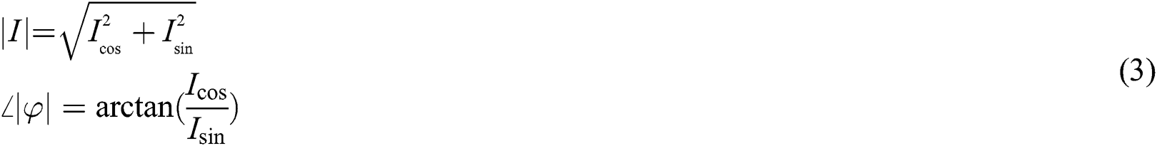
where |I| is amplitude of fundamental current, and ∠|φ| is angle of fundamental current.
Short-circuit current signal in Eq. (1) is filtered by differential filtering and substituted into Eq. (2). Cosine coefficient and sine coefficients of fundamental frequency phasor for short-circuit current after Fourier transform can be obtained [31]. Amplitude and angle of fundamental frequency component after Fourier are
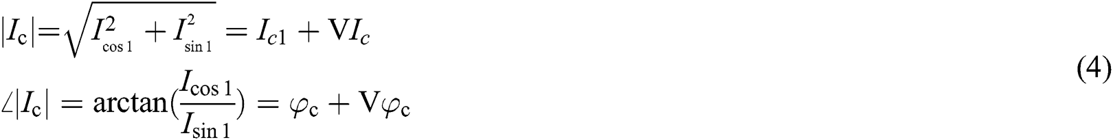
where
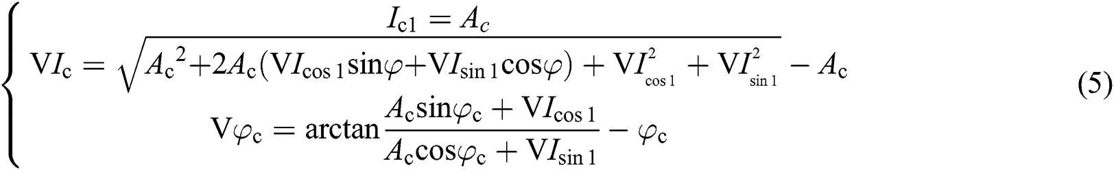
where Icos1 and Isin1 represent cosine coefficient and sine coefficients of fundamental frequency phasor for short-circuit current after Fourier transform. |Ic| and ∠|Ic| represent amplitude and angle of fundamental frequency component after short-circuit current is extracted by DFT. After extraction of short-circuit current by discrete Fourier transform, there is an error amount ΔIc with obtained fundamental frequency component Ic. It shows that amplitude and phase angle of short-circuit current cannot be accurately extracted by Fourier transform, due to rotation speed frequency.
2.2 Adaptability of Directional Protection Based on Angle Comparison between Voltage and Current in Wind Farm
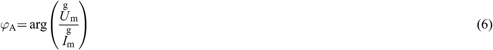
Direction of a fault is determined by angle relationship between current and voltage by directional protection based on angle comparison between voltage and current. The angle between voltage and current is [32]
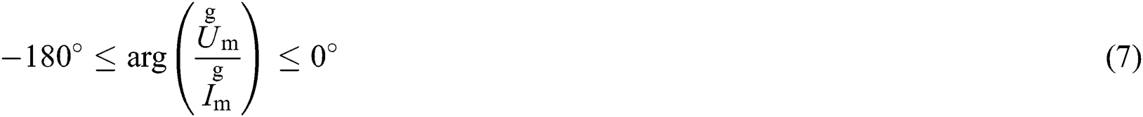
A forward fault occurs, its protection criterion is
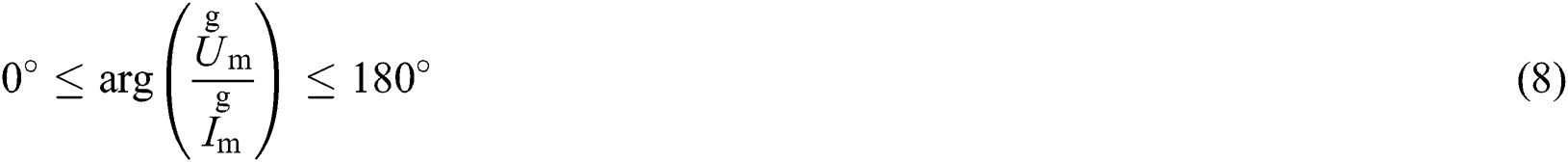
A reverse fault occurs, its protection criterion is
where φA represents angle between voltage and current, and arg represents angle of phasor  . The measured voltage
  and measured current
  are both voltage and current of power frequency calculated by Fourier transform.
After occurrence of a three-phase fault, short-circuit current provided by wind farm is no longer power frequency component. According to analysis in the first section, the crowbar protection contains attenuating rotation speed frequency component, which leads to the error ΔIc when power frequency component current is extracted by DFT. Eq. (4) is substituted into Eq. (6), the angle error measured at the protection installation considering crowbar protection can be obtained as
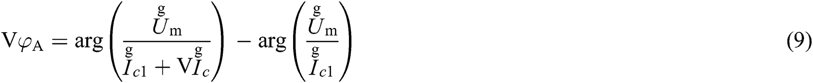
where  = Ascφc,
  = ΔIcΔφc. ΔφA represents angle error between voltage and current. It can be seen from Eq. (9) that due to existence of rotation speed frequency component and transient natural component, φA obtained based on angle comparison by Fourier transform is not accurate, and there is an error angle. The error may cause maloperation and refusal of protection.
3 Time-Domain Protection Based on Model Matching
The above analysis shows that short-circuit current caused by DFIG is very different from short-circuit current provided by traditional motor, which will cause directional protection based on angle comparison by Fourier transform to operate incorrectly. Therefore, time-domain protection based on model matching is proposed. In this section, Single-phase line is used as an example to analyze fault model characteristics of internal and external faults.
3.1 Characteristics of Fault Model for an External Fault
A fault occurs at f in Fig. 2, and characteristics of fault model is analyzed by a π model.
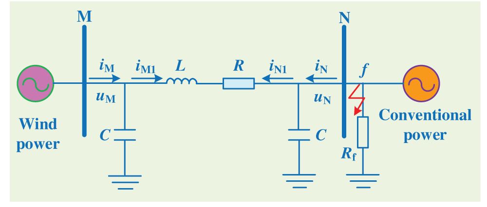
Figure 2: Circuit diagram of an external fault
In Fig. 2, the left side is wind power supply, and the right side is conventional power supply. Rf is transition resistance. uM and uN are measured voltage, iM and iN are measured current at protection installation. iM1 and iN1 are current flowing through resistance and inductance parameters of the transmission line respectively. R and L are resistance and inductance, respectively. C is capacitance to ground of the transmission line.
Eqs. (10), (11), and (12) are established under an external fault.


According to Eqs. (10), (11), and (12), measured voltage and current at protection installation conform to Eq. (13).

3.2 Characteristics of Fault Model for an Internal Fault
A fault occurs at f in Fig. 3, and characteristics of fault model is analyzed by a π model.
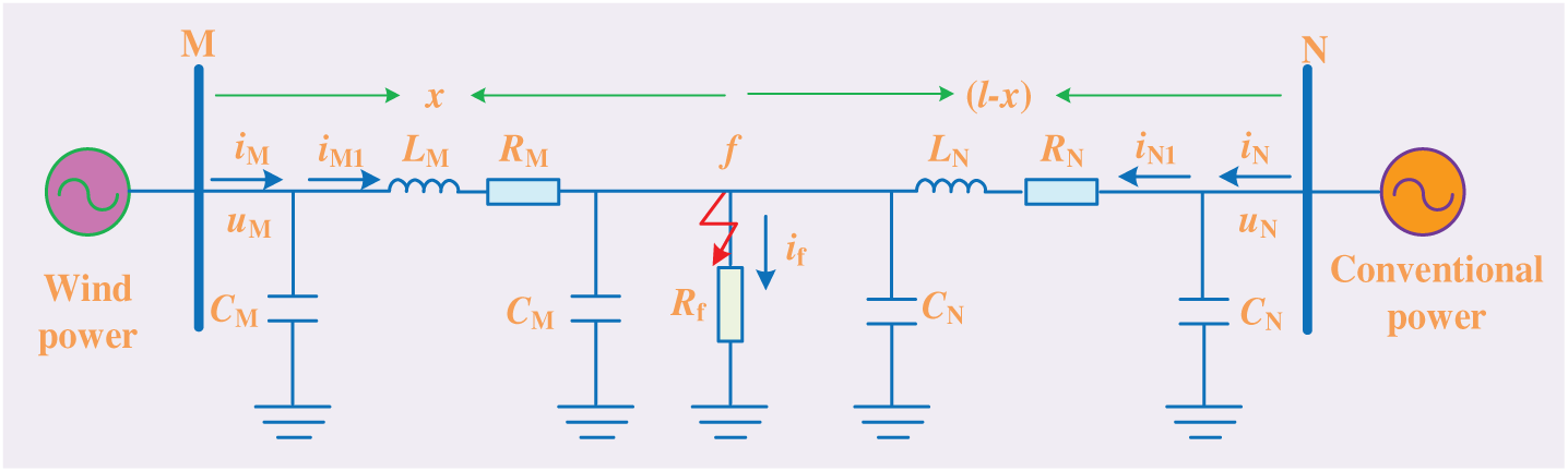
Figure 3: Circuit diagram of an internal fault
In Fig. 3, RM and LM is resistance and inductance from fault to wind power side, respectively; RN and LN are unit resistance and unit inductance from fault to system side, respectively; CM and CN is capacitance to ground from fault to wind power and conventional power, respectively. l represents the full length of the transmission line; x represents the distance from fault to M-terminal; (l-x) represents the distance from fault to N-terminal. Eqs. (14), (15), and (16) are established under an internal fault.


The parameters of resistance and inductance at both ends are different under a fault which does not occur at the midpoint of transmission line, as

So current flowing through parameters of resistance and inductance does not conform to characteristics of equal magnitude and opposite direction, which is iM1+iN1 ≠ 0. Therefore, Eq. (13) does not hold, and the current measured by terminal-N does not conform to calculated current iN in Eq. (13) under an internal fault.
Although π model is different from transmission lines, the transient waveforms of them are similar. A fault occurs on the upper or lower level of the protected transmission lines, which is equivalent to a fault occurs outside the model, and the model itself is not damaged. The relationship between voltage and current measured at both ends should be in accordance with Eq. (13). The protected transmission lines is in normal operation, the model is in a complete state, and relationship between voltage and current measured should also be in accordance with Eq. (13). However, the model is unsuitable anymore in the case of internal fault, so measured voltage and current does not comply with Eq. (13). Hence, internal and external faults can be judged according to whether current measured by one terminal matches with current iN calculated by Eq. (13).
In Eq. (13), the data required by the calculated current comes from time-domain information measured at protection installations, which not only contains information of fault component, but also overcomes impedance of wind power backside. It is not affected by current frequency offset and harmonics on wind farm. In addition, the current calculated according to measurement data matches with measured current, which is theoretically not affected by instability of electrical quantity.
4.1 Hausdorff Distance Algorithm
Hausdorff distance is a kind of graph similarity algorithm, which mainly investigates difference between the overall characteristics of two images [33–35].
It is assumed that there are two finite point sets P = {p1, …, pn} and Q = {q1, …, qn}. In Q, the point with the smallest Euclidean distance from a point pi in P is qj, which meets

where ||•|| represents Euclidean distance between two points. Eq. (19) holds.

For all points in P, the maximum that satisfies Eq. (20) is the one-way Hausdorff distance from P to Q, which is

The one-way Hausdorff distance from Q to P is

The bidirectional Hausdorff distance between P and Q is

where H(P, Q) reflects mismatch between P and Q. The larger H(P, Q), the greater difference between the two sets.
when a fault occurs, current iN calculated by Eq. (13) and current iNS measured by protection installation are calculated by Eq. (21), the bidirectional Hausdorff distance between two currents can be obtained, which is

where H(iN, iNS) is defined as mismatch between calculated current iN and measured current iNS, the smaller H(iN, iNS), the higher similarity between iN and iNS. And H(iN, iNS) is compared with the set threshold, the protection method criteria is

Theoretically, the similarity of iN and iNS is quite high under an external fault, H(iN, iNS) tends to 0, and H(iN, iNS) is larger under an internal fault. It is appropriate to set threshold to 0.2, considering the effectiveness of protection action.
For three-phase lines, voltage and current measured by measuring terminal are substituted into the Karenbauer transform, which is applied for phase mode transform to obtain its corresponding zero mode component and aerial mode component.
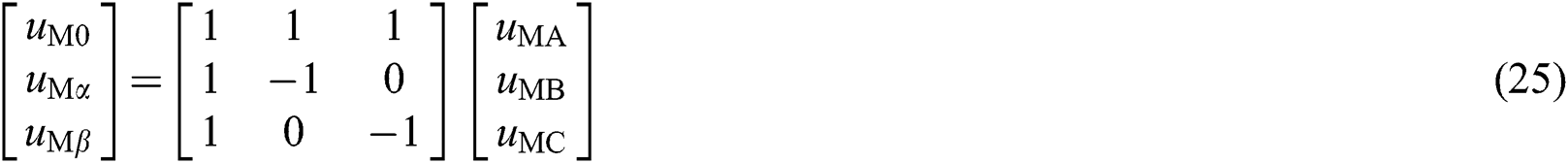
where uMA, uMB, and uMC are three-phase voltages measured at terminal-M; uM0 is zero-mode voltage; uMα and uMβ are three aerial-mode voltages, respectively. Similarly, the phase-to-mode conversion is performed on three-phase current at terminal-M, and phase-to-mode conversion is performed on three-phase voltage and current at terminal-N to obtain corresponding aerial-mode components. C in Eq. (13) is positive sequence capacitance of unit length for the transmission lines. Therefore, aerial-mode component after phase-mode conversion can be substituted into Eq. (13) to calculate the current, and then be matched with measured aerial-mode current by Hausdorff distance, thereby forming a criterion of identifying internal and external faults.
5 Verification and Analysis of Simulation
5.1 Construction of Simulation Model
In Fig. 4, wind power is connected to a 40 MW wind farm composed of 20 DFIGs, and is connected to conventional power supply through the 110 kV transmission lines. uM, uN, iM, and iN is voltage and current measured at protection installation, respectively. Internal resistance of system power supply is 2 Ω; positive sequence impedance of the transmission lines is (0.034 + j0.415) Ω/km; positive sequence and zero-sequence capacitance is 0.0086 μF/km and 0.0061 μF/km respectively. Zero-sequence impedance is (0.253 + j0.873) Ω/km; length of the transmission lines is 60 km. The rated capacity of main transformer is 150 MVA; the rated voltage is 38.5 kV/110 kV; and voltage percentage is Uk% = 10.5. The rated capacity of box transformer for DFIG is 2.5 MVA; rated voltage is 0.69 kV/38.5 kV. The voltage percentage is Uk% = 6.5. The rated capacity of a single DFIG is 2 MW; rated voltage is 0.69 kV; stator impedance is (0.006813 + j0.1528) pu; rotor impedance is (0.007642 + j0.1359) pu; excitation reactance is 4.0152 pu; and moment of inertia is 3.5 s. The transformer is considered as ideal in the proposed method. Fault location is f1, f2, and f3 respectably. f1 is located outside wind power; f2 is located at transmission line; f3 is located outside conventional power.
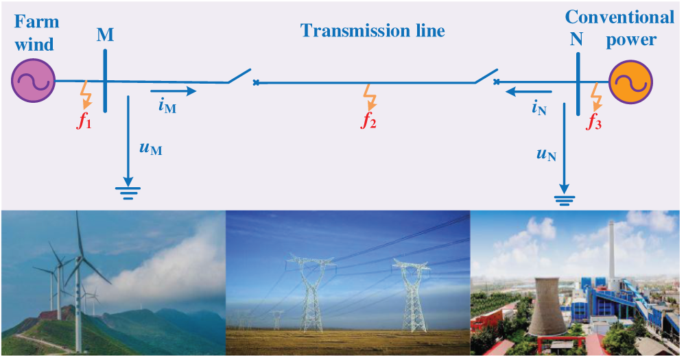
Figure 4: Schematic diagram of wind power connecting system
5.2 Analysis of Operating Characteristics for Directional Element based on Voltage and Current Phase Comparison
A three-phase short-circuit fault occurs in the transmission lines considering crowbar protection, the operating characteristics of components based on positive sequence direction are shown in Tab. 1.
Table 1: Action results obtained by directional protection
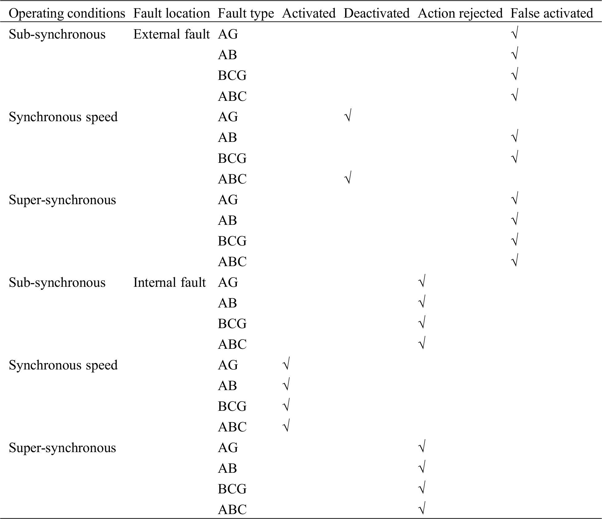
The fundamental frequency component of short-circuit current cannot be accurately extracted by Fourier transform due to rotation speed frequency component, which is short-circuit current provided by DFIG considering crowbar protection. Angle measured by protection installation is inaccurate, which results in refusal and maloperation of protection action.
5.3 Verification of Time-Domain Protection Based on Model Matching
A single-phase ground fault occurs at f3 and f5 in Fig. 4. The transition resistance is 0.1 Ω; fault start time is 1 s; fault duration is 0.2 s; fault data is acquired in 2 ms data window; sampling frequency is 20 kHz. The relationship between iN and iNS is shown in Fig. 5. In Fig. 5, iN represents calculated current, and iNS represents measured current, as does the meaning of iN and iNS that appear in the simulation below.
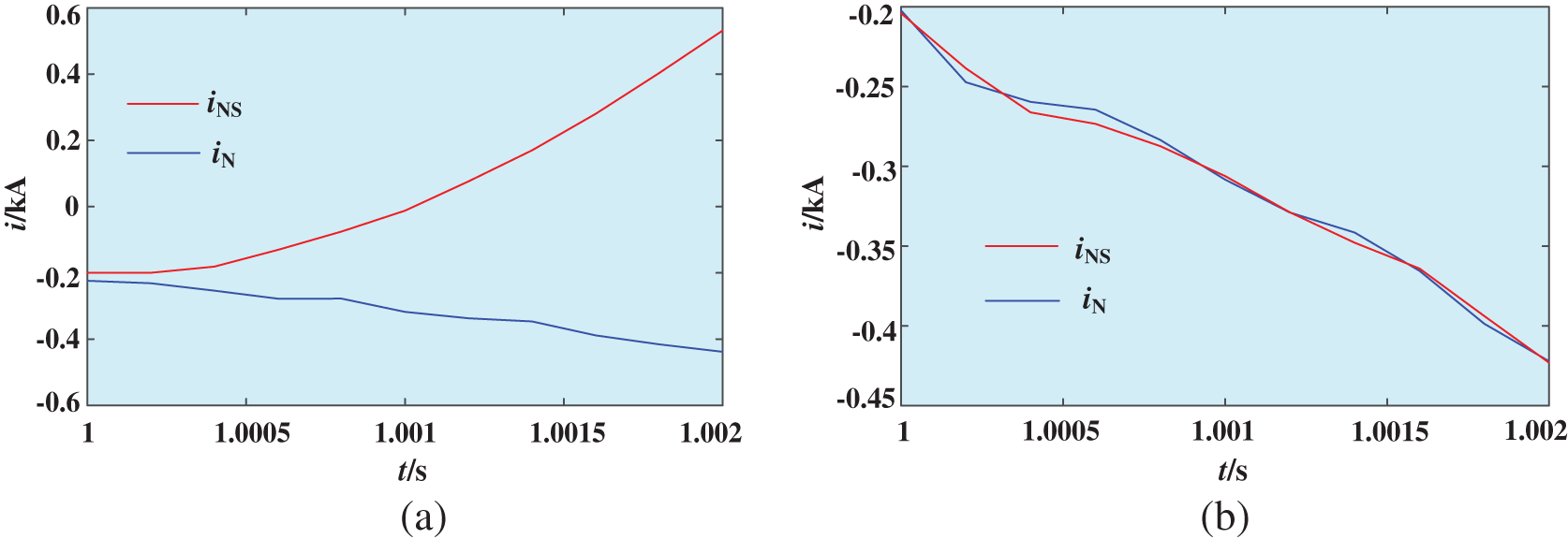
Figure 5: The relationship between iN and iNS. (a) Under an internal fault, (b) Under an external fault
In Fig. 5, when a fault occurs outside system side, the similarity of iN and iNS is quite high. When an internal fault occurs, the similarity of iN and iNS is quite low. H(iN, iNS) under an external fault is 0.0089, which is close to 0. H(iN, iNS) under an internal fault is 0.7648, which is greater than set value. Therefore, the calculated current can be matched with measured current, and internal and external faults can be identified according to similarity. A longer sampling time window will be required at the higher sampling frequency by this method. The proposed method only needs to extract the first few sampling points of the fault signal, so the sampling frequency is lower. And a sampling device with the stronger processing capabilities will be required at the higher sampling frequency. The sampling frequency of actual sampling device on site is usually within 20 kHz. Therefore, the sampling frequency of the method proposed in this article is suitable for field operation.
5.4 Verification of Protection Performance
5.4.1 Fault Type and Fault Location
A fault occurs at locations f1, f2, and f3 in Fig. 4; f4 represents fault location at wind power outlet; f5 represents fault location at conventional power outlet, and 15 km, 45 km distances from terminal-M (respectively recorded as f6, f7). The relationship between iN and iNS is shown in Figs. 6, 7, and 8. H(iN, iNS) at different fault location and fault type are shown in Tab. 2.
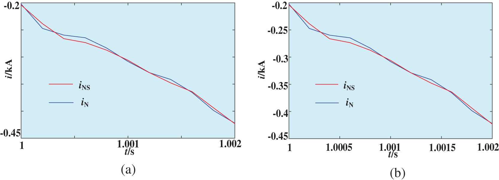
Figure 6: The relationship between iN and iNS. (a) When fault location is outside system side, (b) When fault location is outside wind power side
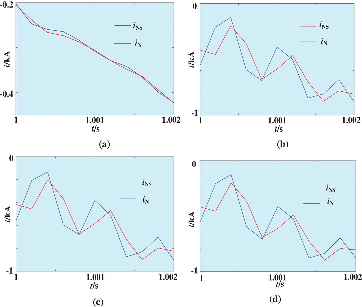
Figure 7: The relationship between iN and iNS under different fault types. (a) AG, (b) AB, (c) ABG, (d) ABC
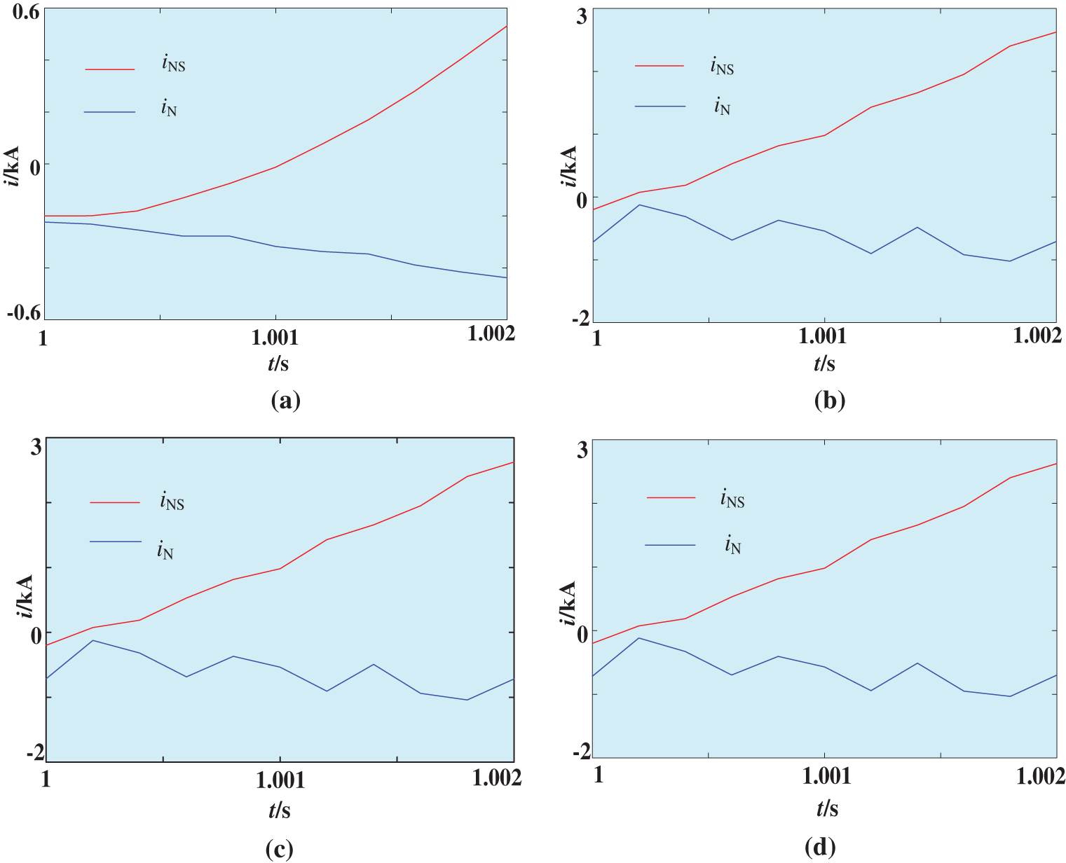
Figure 8: The relationship between iN and iNS. (a) AG, (b) AB, (c) ABG, (d) ABC
Table 2: H(iN, iNS) under different fault locations and different fault types
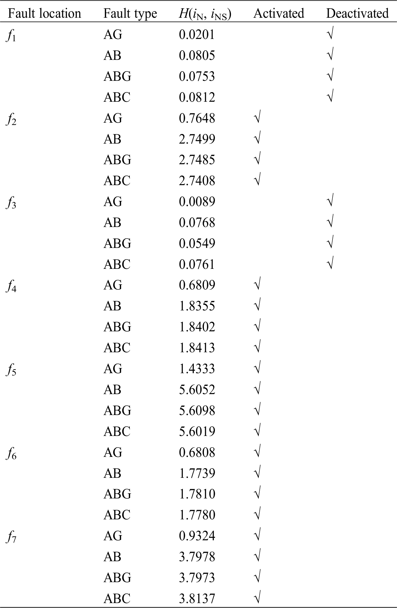
In Tab. 2, H(iN, iNS) all less than 0.2 under an external fault, and the similarity of calculated current and measured current is quite high. H(iN, iNS) all greater than 0.2 under an internal fault, and the similarity of calculated current and measured current is quite low. Therefore, this method is less affected by fault types and fault locations.
5.4.2 Effect of Transition Resistance
A fault occurs at f2 and f3; fault type is A-phase ground fault; transition resistance is set to 20 Ω, 50 Ω, 80 Ω, and 120 Ω, respectively. The curves of waveform for iN and iNS under different transition resistances are shown in Figs. 9 and 10. H(iN, iNS) is shown in Tab. 3. H1(iN, iNS) and H2(iN, iNS) represents the value of a fault location is f2 and f3 respectably.
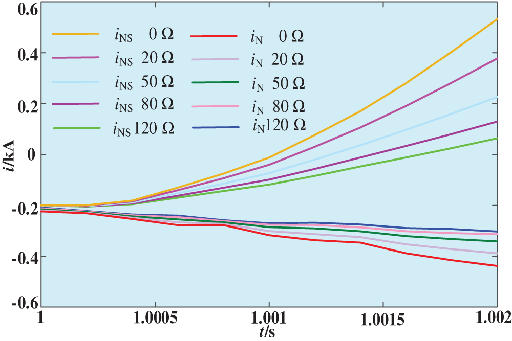
Figure 9: The relationship between iN and iNS under different transition resistances of an internal fault
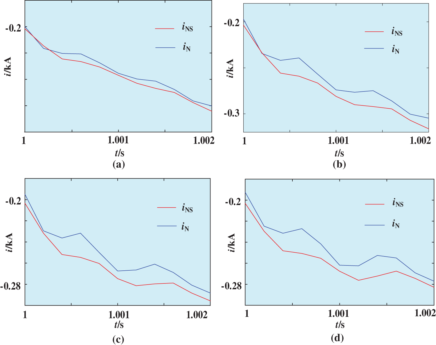
Figure 10: The relationship between iN and iNS under different transition resistances of an external fault. (a) 20 Ω, (b) 50 Ω, (c) 80 Ω, (d) 120 Ω
Table 3: H(iN, iNS) under different fault locations and different fault types
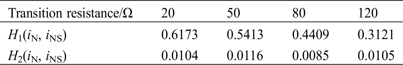
In Tab. 3, H(iN, iNS) is greater than 0.2 under an internal fault, and H(iN, iNS) is less than 0.2 under an external fault, which can be correctly distinguish internal and external faults. In this protection method, the waveform characteristics of calculated current depend on waveform characteristics of voltage and current measured on both sides. It does not directly depend on magnitude of short-circuit current, so H(iN, iNS) can also meet requirements of criterion under different transition resistances.
Power systems are susceptible to electromagnetic interference, and there must be some noise in their signals. A fault occurs at f1, f2, and f3, respectively; transition resistance is set to 20 Ω and 100 Ω, respectively. Therefore, H(iN, iNS) of Gaussian white noise under signal-to-noise ratio (SNR) of 10 dB, 15 dB, and 20 dB and under various short-circuit fault types are shown in Tab. 4.
Table 4: H(iN, iNS) under different SNR and different fault types
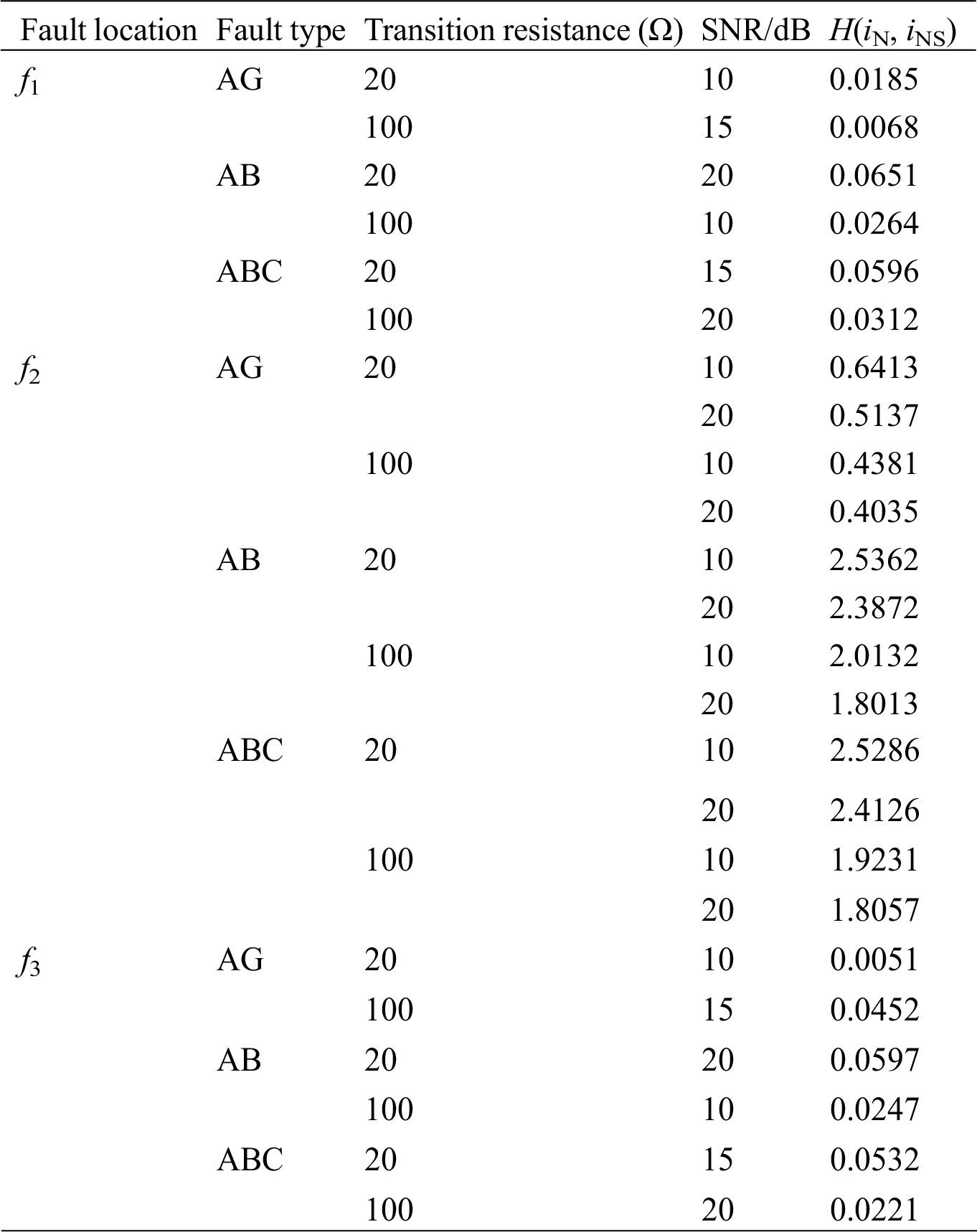
In Tab. 4, when SNR is 20 dB and transition resistance is 100 Ω, H(iN, iNS) is still greater than set value under an internal fault, H(iN, iNS) is less than set value under external faults and the effect of noise on the proposed method is little.
Characteristics of short-circuit current provided by DFIG considering crowbar protection is analysed. According to expressions of amplitude and angle for fundamental frequency current obtained by Fourier transform, furthermore, action characteristics of traditional directional protection based on angle comparison of voltage and current and time-domain protection based on model matching are analysed, and the following conclusions are obtained:
1. Derivation and simulation analysis show that measurement angle based on Fourier transform is affected by rotation speed frequency component, which causes traditional directional protections using angle comparison between voltage and current to operate incorrectly. However, the time-domain protection based on model matching is not affected by rotation speed frequency component.
2. Hausdorff distance can be used to match the waveforms through analysis, thereby can be formed a criterion for correctly identifying internal and external faults. The algorithm does not require length of time window, can be carried out in a shorter window.
3. The proposed method has a high accuracy and efficiency in fault identification, which is not affected by fault locations, fault types, and noise. Accuracy of the protection action is about 20% higher than accuracy of the traditional directional protection under high-impedance faults. Theoretically, it is not affected by the frequency deviation of current on wind power system, high-order harmonics, and impedance variations.
Future studies will be focused on the following two aspects:
a) The measured data will be used to verify feasibility of the proposed method;
b) The proposed method will be tested in RTDS.
Acknowledgement: The authors gratefully acknowledge the support of the National Natural Science Foundation of China (51977102 and 51807084).
Funding Statement: This paper is supported in part by the National Natural Science Foundations of China under Grant Nos. 51977102 and 51807084.
Conflicts of Interest: The authors declare that they have no conflicts of interest to report regarding the present study.
References
1. Ayoub, H., Bani-Hani, E. H. (2020). Performance and cost analysis of energy production from offshore wind turbines. Energy Engineering, 117(1), 41–47. DOI 10.32604/EE.2020.010372.
2. Yang, B., Wang, J. B., Zhang, X. S., Yu, T., Yao, W. et al. (2020). Comprehensive overview of meta-heuristic algorithm applications on PV cell parameter identification. Energy Conversion and Management, 208, 112595. DOI 10.1016/j.enconman.2020.112595.
3. Ayodele, T. R., Ogunjuyigbe, A. S. O., Olarewaju, R. O., Munda, J. L. (2020). Comparative assessment of wind speed predictive capability of first-and second-order Markova chain at different time horizons for wind power application. Energy Engineering, 116(3), 54–80. DOI 10.1080/01998595.2019.12057062.
4. Yang, B., Yu, T., Zhang, X. S., Li, H. F., Shu, H. C. et al. (2019). Dynamic leader based collective intelligence for maximum power point tracking of PV systems affected by partial shading condition. Energy Conversion and Management, 179, 286–303. DOI 10.1016/j.enconman.2018.10.074.
5. Ehab, B. H., Ahmad, S., Abdallah, S., Ahmad, G., Hamad, A. et al. (2019). Evaluating performance of horizontal axis double rotor wind turbines. Energy Engineering, 116(1), 26–40.
6. Yang, B., Zhong, L. E., Yu, T., Li, H. F., Zhang, X. S. et al. (2019). Novel bio-inspired memetic slap swarm algorithm and application to MPPT for PV systems considering partial shading condition. Journal of Cleaner Production, 215, 1203–1222. DOI 10.1016/j.jclepro.2019.01.150.
7. Ryndzionek, R., Sienkiewicz, L. (2020). Evolution of the HVDC link connecting offshore wind farms to onshore power systems. Energies, 13(8), 1914.
8. Zheng, T., Zhao, Y. T., Zhu, Y. F. (2020). Overcurrent protection scheme for collector lines in wind farm based on fault component current correlation analysis and multi-agent system. IET Renewable Power Generation, 14(2), 313–320. DOI 10.1049/iet-rpg.2019.0315.
9. Kapoor, G., Yadav, A. (2020). Protection of series capacitor compensated wind park connected transmission line using HHT. International Conference on Power Electronics & IoT Applications in Renewable Energy and Its Control, pp. 8–13, Mathura, Uttar Pradesh, India.
10. Rezaei, N., Nasir Uddin, M., Khairul Amin, I., Lutfi Othman, M., Marsadek, M. (2019). Genetic algorithm-based optimization of overcurrent relay coordination for improved protection of DFIG operated wind farms. IEEE Transactions on Industry Applications, 55(6), 5727–5736. DOI 10.1109/TIA.2019.2939244.
11. Tripathy, L. N., Jena, M. K., Samantaray, S. R. (2014). Differential relaying scheme for tapped transmission line connecting UPFC and wind farm. International Journal of Electrical Power & Energy Systems, 60, 245–257. DOI 10.1016/j.ijepes.2014.02.024.
12. Ghorbani, A., Mehrjerdi, H., Al-Emadi, N. A. (2017). Distance-differential protection of transmission lines connected to wind farms. International Journal of Electrical Power & Energy System, 89, 11–18. DOI 10.1016/j.ijepes.2017.01.002.
13. Yu, F., Jia, K., Yang, Z., Li, Y. B., Bi, T. S. (2018). Impact of inverter-interfaced renewable energy generators on distance protection and an improved scheme. IEEE Transactions on Industrial Electronics, 66(9), 7078–7088.
14. Jayanthi, P., Devaraj, D. (2019). Performance study of DFIG based grid connected WECS using crowbar and without crowbar. IEEE International Conference on Intelligent Techniques in Control, Optimization and Signal Processing, pp. 1–3, Tamilnadu, India.
15. Abdellatif Walid, S. E., Kasem Alaboudy, A. H., Azmy, A. M. (2019). Comparison between outer crowbar and RSFCL for LVRT capability enhancement of wind turbines conversion system. 21st International Middle East Power Systems Conference, pp. 884–889, Cairo, Egypt.
16. Chen, Y., Wen, M. H., Hu, L. X., Qi, X. W., Zheng, J. C. et al. (2019). Fault direction identification for wind power integration system. Journal of Engineering, 2019(16), 2520–2524. DOI 10.1155/2019/6413608.
17. Wu, C., Yu, Q. (2018). Analysis and countermeasure of delay of line differential protection caused by CT transient saturation in faults in wind farms. Chinese Automation Congress, pp. 3209–3212, Xi’an, China.
18. Davari, M., Alizadeh Mousavi, O. (2009). Analysis and comparison of the lightning overvoltage in the AC connected and VSC based HVDC connected wind farms. TENCON IEEE Region 10 Conference, pp. 1–6, Singapore.
19. SuoNan, J. L., Liu, K., Song, G. B. (2011). A novel UHV/EHV transmission lines pilot protection based on fault component integrated impedance. IEEE Transactions on Power Delivery, 26(1), 127–134. DOI 10.1109/TPWRD.2010.2066292.
20. Zheng, L. M., Jia, K., Bi, T. S., Yang, Z., Fang, Y. (2020). Structural similarity based pilot protection for renewable power transmission lines. IEEE Transactions on Power Delivery. DOI 10.1109/TPWRD.2020.2973505.
21. Suonan, J. L., Yang, C., Song, G. B., Kang, X. N. (2009). Transmission lines pilot protection based on phase-segregated model recognition. IET Generation, Transmission and Distribution, 3(9), 885–890. DOI 10.1049/iet-gtd.2009.0015.
22. Suonan, J. L., Deng, X. Y., Liu, K. (2011). Transmission lines pilot protection principle based on integrated impedance. IET Generation, Transmission & Distribution, 5(3), 1003–1010. DOI 10.1049/iet-gtd.2011.0224.
23. Wang, C. Q., Song, G. B., Kang, X. N., Suonan, J. L. (2015). Novel transmission lines pilot protection based on frequency-domain model recognition. IEEE Transactions on Power Delivery, 30(3), 1243–1250. DOI 10.1109/TPWRD.2014.2363590.
24. Howard, D. F., Habetler, T. G., Harley, R. G. (2012). Improved sequence network model of wind turbine generators for short-circuit studies. IEEE Transactions on Energy Conversion, 27(4), 968–977. DOI 10.1109/TEC.2012.2213255.
25. Biswas, S., Nayak, P. K. (2020). A fault detection and classification scheme for unified power flow controller compensated transmission lines connecting wind farms. IEEE Systems Journal, 1–10. DOI 10.1109/JSYST.4267003.
26. Amin, M., Rygg, A., Molinas, M. (2017). Self-synchronization of wind farm in an MMC-Based HVDC system: a stability investigation. IEEE Transactions on Energy Conversion, 32(2), 458–470. DOI 10.1109/TEC.2017.2661540.
27. Sadeghi, H. (2012). A novel method for adaptive distance protection of transmission lines connected to wind farms. International Journal of Electrical Power & Energy Systems, 43(1), 1376–1382. DOI 10.1016/j.ijepes.2012.06.072.
28. Dubey, R., Samantaray, S. R., Panigrahi, B. K., Venkoparao, G. V. (2015). Adaptive distance relay setting for parallel transmission network connecting wind farms and UPFC. International Journal of Electrical Power & Energy Systems, 65, 113–123. DOI 10.1016/j.ijepes.2014.09.033.
29. Zhang, B. H., Wang, J., Yuan, B., Hao, Z. G., Huang, R. M. et al. (2013). Impact of wind farm integration on relay protection: performance analysis for wind farm outgoing transmission line protection. Electric Power Automation Equipment, 33(4), 1–5 (in Chinese).
30. Shu, H. C. (2009). Application of power engineering signal processing. Beijing: Science Press (in Chinese).
31. Fan, X. H., Sun, S. Y., Zhang, X. J., Zheng, X. Y., Wang, Y. et al. (2020). Study on the influence of short-circuit current characteristics of a doubly-fed wind farm on distance protection and protection strategy. Power System Protection and Control, 48(11), 18–27 (in Chinese).
32. Zhang, B. H., Yin, X. G. (2013). Power system relay protection. Beijing: China Electric Power Press (in Chinese).
33. Lin, Y., Xue, S. Q., Guo, T. T. (2014). A method of calculating the Hausdorff distance between parametric curves. Journal of Graphics in China, 35(5), 704–708.
34. Karimi, D., Salcudean, S. E. (2020). Reducing the Hausdorff distance in medical image segmentation with convolutional neural networks. IEEE Transactions on Medical Imaging, 39(2), 499–513. DOI 10.1109/TMI.2019.2930068.
35. Du, L., Lu, X., Li, B., Xu, S. W. (2020). HRRP clutter rejection via one-class classifier with Hausdorff distance. IEEE Transactions on Aerospace and Electronic Systems, 56(4), 2517–2526. DOI 10.1109/TAES.2019.2948513.
Appendix A: The coefficients of each component for short-circuit current considering crowbar protection
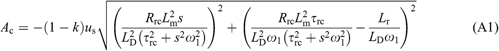


where us is terminal voltage of DFIG after a fault; Rs is stator resistance; Rrc is rotor equivalent resistance considering crowbar protection. Ls and Lr are stator and rotor inductance of DFIG respectively. Ls = Lm + Lσs, Lr = Lm + Lσr. Lσs and Lσr are leakage inductance of stator and rotor respectively, and Lm is mutual inductance of stator and rotor windings. s = (ω1 − ωr)/ω1; s is slip rate.
 | This work is licensed under a Creative Commons Attribution 4.0 International License, which permits unrestricted use, distribution, and reproduction in any medium, provided the original work is properly cited. |