DOI:10.32604/EE.2020.012482
| Energy Engineering DOI:10.32604/EE.2020.012482 | |
| Article |
Diffusion of a Nonvolatile Fuel Spray in Swirl Flow
1School of Energy and Power Engineering, Xi’an Jiaotong University, Xi’an, 710049, China
2State Key Laboratory of Mechanical Strength and Vibration, School of Aerospace, Xi’an Jiaotong University, Xi’an, 710049, China
3School of Automobile, Chang’an University, Xi’an, 710061, China
*Corresponding Author: Yanju Wei. Email: weiyanju@xjtu.edu.cn
Received: 01 July 2020; Accepted: 17 August 2020
Abstract: The diffusion of fuel spray in swirl flow is vital for the combustion of diesel engine, however, the researches on this is still mysterious due to the obstacles on direct investigations on a real engine. The research of intake swirl in engine at present normally use CFD simulation or based on data analysis of combustion and exhaust emission, the specific mixing process of fuel in swirl flow still not very clear. In this paper, a rapid compression machine (RCM) with an optical combustion chamber was established with the mean compression velocity of 7.55 m/s. Three kinds of flow fields, including intense swirl field, weak swirl field and turbulent field, were conducted to investigate the diffusion characteristics of injected fuel, the mixing processes of fuel spray in the swirl flow fields were recorded by the high-speed camera. Experimental results show that the mixing of fuel spray in air consists of four stages: fuel injection, wall approaching, rapid diffusion and final diffusion. The fuel spray is firstly bended by the lateral flow of the swirl field, then liquid fuel is blown onto, and coats on, the sidewall. The fuel on the sidewall is finally enrolled into the chamber plenum afterwards in gaseous phase via the spiral arms (in swirl fields) or random routes (in turbulent field) At last the fuel disperses all over the chamber. The results give an intuitive observation and help better understand the air-fuel mixing process in diesel and direct inject gasoline engines.
Keywords: Rapid compression machine (RCM); diesel spray; swirl flow field; air-fuel mixing
Energy efficiency and environmental sustainability are the ultimate concerns that drive the research of internal combustion engine towards high efficiency and ultra-low emission [1]. The fuel-air mixing process is vital for the sufficient combustion and the generation of particulate matter (PM) emissions, especially for gasoline direct injection (GDI) engines and diesel engine. The particulate matters are formed in the fuel-rich and high-temperature regions, and they depend highly on the fuel-oxygen distribution situations. Multiple fuel-air preparation strategies, such as homogeneous charge, partially premixed and reactivity-controlled compression ignition (abbreviated as HCCI, PPCI and RCCI, respectively), have been developed to improve this distribution [2], however, all these strategies encounter the power insufficiency at high engine load, where the power has to be promised by the over charge of fuel and the emissions, especially PM emission, thus deteriorates.
The preparation of combustible fuel-air mixture is determined by various factors, such as the fuel properties, injection pressure, air flow conditions and so on. Organizing the intake swirl flow in the chamber of compression ignition engine is an effective way to improve the mixing of fuel-air and the following combustion in the cylinder. Although the spray characteristics of diesel has been widely studied through computational simulations [3–5] and experiments [6–8], the effect of swirl flow on the fuel spray diffusion was seldomly studied due to the high threshold of visualization of combustion process. Kim et al. [9] studied the characteristics of the swirl flow its effects on combustion and flame propagation on an optical, single-cylinder diesel engine. They found that swirl flow improved the uniformity of fuel distribution, thereby decreased ignition delay and promoted combustion efficiency. Perini et al. [10] developed a comprehensive model of an optical, single-cylinder light-duty diesel engine and studied the swirl in-cylinder flows generated by variable throttles in the intake pipe, but fuel injection was not included. The combustion characteristics [9–12] and soot formation process [13] have also been widely investigated on optical engines. Catapano et al. [14] studied the air-fuel mixing and combustion behavior of gasoline-ethanol blends in an optical GDI engine. However, all the investigations present many challenges from the equipment cost and recording method, the high cost of the optical internal combustion engine prevents it from wide application. And furthermore, the high uncertainty of cylinder wall temperature conditions and low repetitions between two neighbor cycles make it difficult to quantitatively investigate the combustion process. Thus, computational fluid dynamics (CFD) simulation methods [15–17] or just the data analysis of combustion and emission of engine [18–20] are usually utilized to study the swirl flow in engine chamber. In this study, a rapid compression machine (RCM) was used to intuitively observe the mixing process of fuel spray in swirl flow.
RCM was developed to overcome the disadvantages of optical engines and typically used for studying the ignition behavior of fuels at low to moderate temperature conditions, or investigating the flame propagation characteristics in the combustion chamber. Guibert et al. [21] created the high turbulence conditions in their RCM by using a reaction chamber that had a contracting geometry, the intent of their work was to identify various combustion modes during autoignition, and investigate the influence of turbulence scale and intensity on the combustion modes observed. Strozzi et al. [22] studied the influence of turbulent fluid dynamics on the evolution of autoignition and interactions with flame front propagation under low turbulence conditions. In recent years, the RCM studies mainly focused on the ignition delay of homogeneous charge fuel-air mixtures, and the air flow, fuel injection and fuel-air mixing characteristics were hardly involved. Yu et al. [23] investigated the autoignition characteristics of decalin, and systemically studied the dependence of ignition delay time on compressed pressure, equivalence ratio, and oxygen concentration. Wadkar et al. [24] studied the ignition delay characteristics of stoichiometric mixtures of ethanol and air for different mixture preparation methods. Wei et al. [25] observed the knocking phenomenon of homogeneous premixed isooctane and methane comparatively under different thermal boundary conditions. Lee et al. [26] investigated the hydrogen effects on the ignition delay of n-butane and numerical analysis. In order to calculate the compression temperature, adiabatic core assumption was widely used in their research. So in their RCM experiments, for convenience, the aerodynamic effects do not play any significant role at the short time scales encountered in the RCM, thus the roll-up vortex created during the RCM compression process usually be ignored [27]. Wu et al. [28] even designed an optimized creviced piston to suppress the piston-driven vortex and enhance the validity of the “adiabatic core” approximation in RCM.
In this paper, a new RCM was developed with an optical chamber to study the mixing process of fuel spray in the swirl flow. Three kinds of flow fields, including intense swirl field, weak swirl field and turbulent field, were created in the optically accessible chamber, and the diffusion process of diesel spray under different injection pressures were investigated with a high-speed camera system. The study will help better understand the air-flow motion of fuel mixing process in combustion chamber, and provides some certain reference value for visualization research of the fuel/air mixing promotion in diesel engine chamber where difficult to perceive directly.
The RCM was a single-stroke device that provides in-cylinder conditions similar to internal combustion engine. a diesel-engine-like swirl flow field was created in this RCM system, the 3D model and schematic diagrams were shown in Fig. 1. The RCM system consisted of subsystems including air supply subsystem, optical chamber module, dynamic system, fuel supply system, high-speed camera data acquisition system and controlling system. Fig. 1b shows the model and the diagram of RCM system. An electric motor (7.5 kW, 3000 r/min (revolutions per minute)) was used to drive the linear motion system (Thomson. Linear Motion. Optimized. Type WH08Z200), the load, i.e., a series of steel bulks, was firstly speed up to 10 m/s, then the electric controlled clutch cut off the dynamic transmission and the steel bulks rushed freely to collide and push the piston module to compress the in-cylinder gas. At the end of compression stroke, the piston module was locked by the locking pin as shown in the subfigure in Fig. 1a.
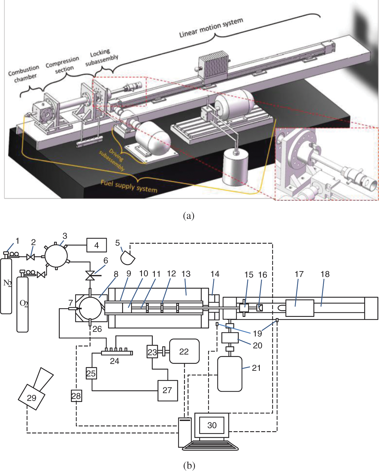
Figure 1: The (a) 3D model and (b) schematic diagram of the rapid compression machine (RCM) system. (1. N2/O2 bottle; 2. Valve; 3. Mixing tank; 4. Vacuum pump; 5. Backlight; 6. Three-way switch; 7. Fuel injector; 8. Chamber block; 9. Cylinder; 10. Piston; 11. Push rod; 12. Positioning plate; 13. Cylinder support; 14. Locking block; 15. Locking pin; 16. Bearing bowl; 17. Steel bulks; 18. Linear motion system; 19. Position sensors; 20. Clutch; 21, 22. Electric motor; 23. High pressure fuel pump; 24. Common rail; 25. Pressure release valve; 26. Pressure sensor; 27. Fuel tank; 28. Amplifier; 29. High-speed camera; 30. Computer)
The RCM had a thin cylindrical combustion chamber with a bore of 50 mm and effective thickness of 14.0 mm, where the thickness of two Teflon gaskets is included. The chamber was separated from cylinder and their axes were perpendicular to each other, as illustrated in Fig. 2, they were connected by a swirl hole. The three types of swirl holes (Φ6 mm) were designed to intersect with cylinder head face with angles of 45°, 25° and 0° to create tangential, oblique and direct flow, respectively. It is noted that the swirl blocks invaded the combustion chamber from the edge, and thus the head-view shape of the chamber is not an intact circle.
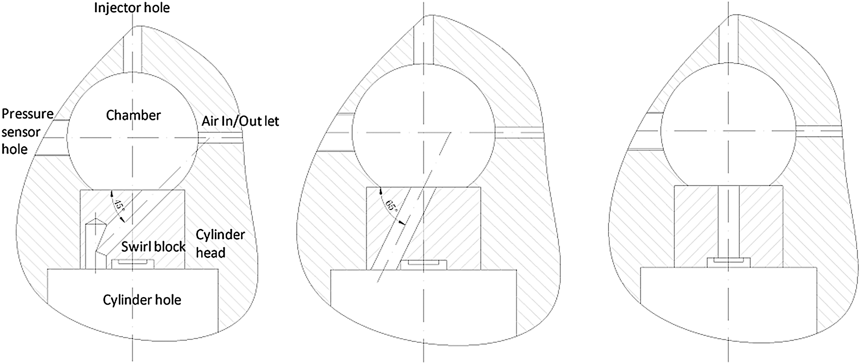
Figure 2: The mounting diagram of combustion chamber block, cylinder and swirl blocks to create (left) tangential, (middle) oblique and (right) direct flow. With the chamber in the size of Φ50 mm × 15 mm, swirl hole in Φ6 mm, and cylinder in Φ50 mm (ID) × 600 mm
The clearance volume at the end of compression was composed of three sections including combustion chamber volume, piston head volume and swirl hole, thus the equivalent clearance height 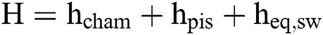 . Where, hcham was the height of chamber (20 mm) including two 2 mm thick Teflon gaskets, 24 mm; hpis inferred the clearance height between cylinder head and piston, 3 mm; and heq,sw denoted the equivalent height of swirl holes, which was calculated as 0.58 mm, 0.50 mm and 0.43 mm for tangential, oblique and direct flow, respectively. Since the differences among three equivalent heights were neglectable, the mean value of 0.5 mm was taken for compression ratio calculation. Thus, the equivalent clearance height H was 27.5 mm on average. The stroke (S) was select as 280 mm in this study, resulting in a compression ratio CR = 1 + S/H = 11.2.
The compression pressure curves in Fig. 3 showed that the compression began from the intense pressure fluctuation caused by the collision of steel bulk onto piston module; the compression stroke took 37.08 ms on average, so the mean piston velocity of compression (vc) was 7.55 m/s. The peak compression pressure was around 1.6 MPa and then it decreased due to heat loss and air leakage.
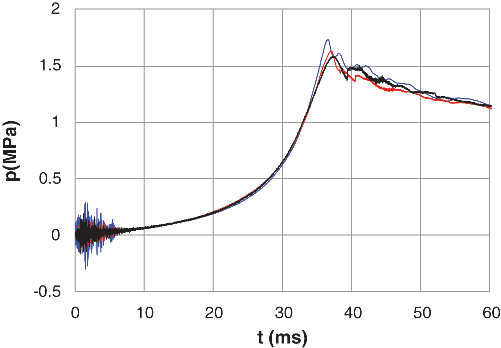
Figure 3: Compression pressure curves of the RCM system, stroke = 280 mm, mean velocity (vc) = 7.55 m/s
2.4 Experimental Test Conditions
Commercial 0# diesel was utilized as the test fuel.It was supplied by a BOSCH high pressure common rail fuel injection system, the injector was specially designed to have a single orifice with diameter of Φ0.12 mm (shown in Fig. 4). The rail pressure was stabilized at 60 MPa and 40 MPa, respectively, within the range of ±2 MPa by a pressure maintaining valve. The pulse width of injection was controlled at 0.5 ms in all testing conditions.
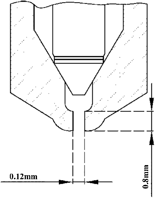
Figure 4: Structure of injector orifice
The supplied air was premixed in the mixing tank up to 0.5 MPa from 80% nitrogen and 20% oxygen (both of 99.999% purity) by using Dalton’s law of partial pressure. Then, the nitrogen/oxygen mixture was stirred sufficiently at a constant temperature to ensure homogeneity. The chamber was washed, by charging and discharging with target gas mixture, for 5 times before the final compression to minimize the influence of residual gas.
The chamber pressure was acquired by a piezoelectric transducer (Kistler 7061B) with the frequency of 10 MHz. The injection and mixing process were recorded in the shadow method by a high-speed camera (Phantom MIRO eX4) at 1900 fps @ 800 × 600 pixels. The white backlight was generated by a 300 W light-emitting diode (LED) metrix. To analyze the data from video, the RGB images of fuel injection were firstly transformed to gray image. Then the gray values of the pixels were binarized with a threshold value of 128. In this way, the cloud area of fuel spray (Sspray) could be obtained by counting the number of dark pixels, then the normalized diffusion area A = Sspray/Schamber, defined as the ratio of Sspray to the sectional area of chamber, was adopted for analysis and comparison.
The instant rotary velocity (nswirl) was calculated from the angle difference of the tracing polystyrene particles in the neighbor images,

as illustrated in the subfigure of Fig. 5. In order to compare the swirl flow with that of diesel engine, the swirl intensity was evaluated by an equivalent swirl ratio (Ω), i.e., the rate of Ω = nswirl/nRCM, where nRCM = 30vc/S, representing the “rotation speed” of compression stroke when RCM’s treated as an engine, r/min. Fig. 5 shows the development of instant equivalent swirl ratios of tangential, oblique and direct flow.
Among the three flows, the tangential flow resulted in the largest Ω with the peak value of 5.8 at the end of compression, which was comparable with that of Benajes’s [20] and Dembinski’s [18] engine, the largest swirl ratio were 5.33 and 6.7, respectively. The swirl flow degraded rapidly due to the friction of chamber walls in the initial 5 ms to 10 ms, and then degenerated almost linearly for another 150 ms. The swirl ratios of oblique and direct flow were similar to that of tangential flow, however, with the overall values of tangential > oblique > direct flow. Since diesel engine runs always at the speed ranging within 1000 r/min − 2000 r/min, with the stroke time varying from 15 ms to 30 ms, thus the three typical swirl flows resulted in this RCM could represent the strong, medium and weak swirl conditions in diesel engine.
3.2 Spray Diffusion in Tangential Flow Field
3.2.1 Developments of Spray Diffusion in Swirl Flow
Fig. 6 shows the histories of diesel spray diffusion processes under different injection pressures. It can be seen that the processes were similar for the two sprays. Unlike the situation without compression, when swirl flow was generated, the fuel spray never collides on the sidewall, it was bended downstream along the swirl flow soon after injection, and at last the spray front meets the injector. At this time, the fuel cloud occupied most of the plenum except for the center of the chamber. The injection lasts 5 ms in this study and the stage was named as the “injection” process.
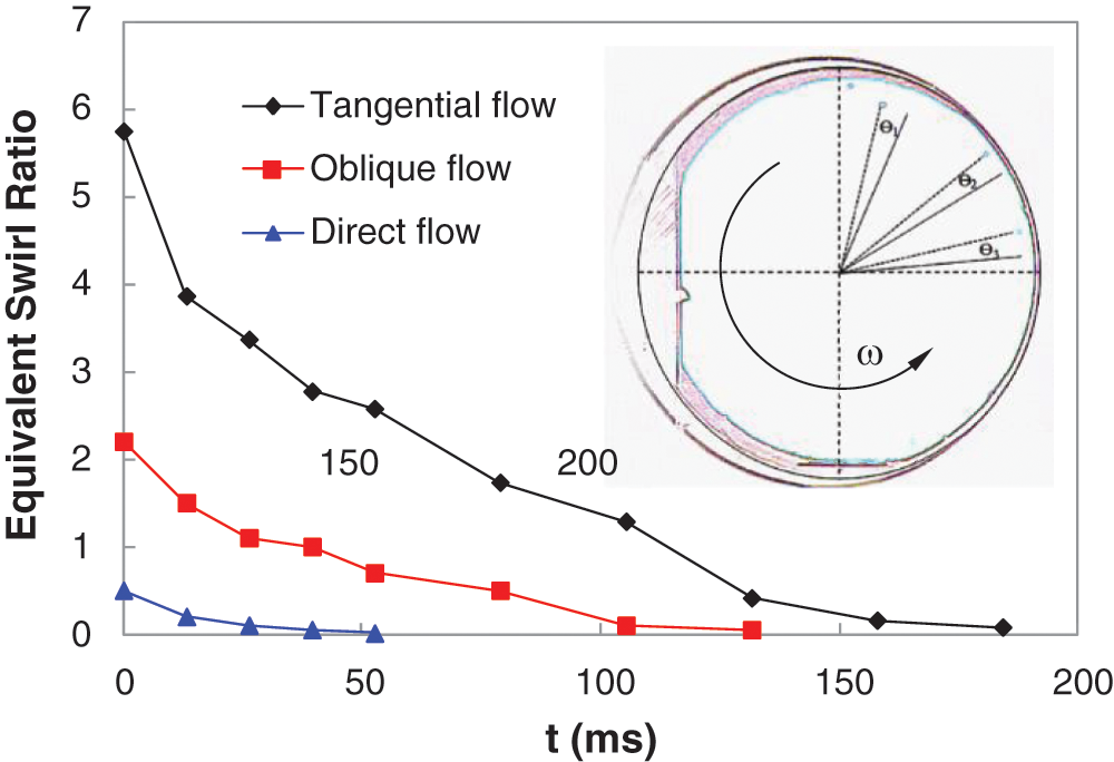
Figure 5: Evolution of instant equivalent swirl ratio of tangential, oblique and direct flow. The subfigure shows the calculation of a typical rotation speed from the tracing particles in two neighbor images
The fuel mist was blown towards chamber wall rapidly in approximately 2 ms and coated on the sidewall evenly, leaving the chamber space fuel-free. This situation maintained till the air velocity at the sidewall decreased to be lower than that of the inner layer of flow. This process was defined as the “wall-approaching” process.
Since the swirl flow was approximately a rigid body flow with the highest velocity at the edge and lowest at the center, and the friction area increases in the form of r2, where r was the distance of an arbitrary point to chamber circle center, and at the radial edge of the chamber, the sidewall surface became another main friction source. As a result, the flow velocity at the sidewall decayed most rapidly and this result in a relative high-pressure annular zone adjoining to the sidewall.
The fuel mist coated on the sidewall was transported again into the swirl flow by the centripetal flow caused by the high-pressure zone. As shown in Fig. 7, the tangential flow (vT) and centripetal flow (vn) combine and form an oblique flow (vO). As the vn decreased while vT increased slightly when approaching to the circle center, the path line of fuel transportation formed a spiral asymptote and finally a circle with the highest vT and vn = 0. At last, the swirl flow transportation exhibited as a tiny “typhoon”. Wang et al. [17] came to a similar conclusion by CFD simulation. They found that, the fuel-air mixture gradually rotated around the centerline of the cylinder under the action of the swirl, thereby accelerated the fuel-air mixing to promote combustion. Moreover, Wei [15] also found that the big swirl ratio could reduce the concentration of the mixture on the combustion chamber sidewall. As the fuel moved continuously into the high-speed low-pressure annular zone via the spiral arms, the fuel-air mixture became richer, so that less backlight could pass through resulting in an unrecognizable black image. However, the fuel could hardly penetrate into the “typhoon eye” (center of the swirl flow) because of the high pressure and centrifugal force, until the diffusion force overcame the centrifugal force as the flow degraded. The diffusion of fuel vapor from annular zone into the “typhoon eye” seemed to be a replication of that from sidewall to the annular zone, whereas with a floating “eye”.
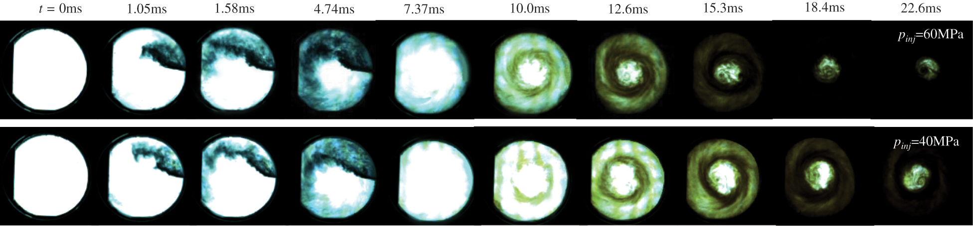
Figure 6: Evolution of diesel spray diffusion process in tangential flow swirl field
As mentioned above, the preparation of fuel-air mixture of diesel engine actually underwent four stages, including (1) fuel injection, (2) wall approaching, (3) rapid diffusion and (4) final diffusion. The different colors of fuel concentration in different stages inferred the different phase of fuel. The black and light blue of the spray in injection stage showed the fuel in liquid phase, and dark and light yellow in the latter two stages meant fuel in vapor phase of different concentrations.
3.2.2 Normalized Diffusion Area
The four periods can be clearly seen from Fig. 8, which shows the development of normalized diffusion area of diesel spray and its increasing rate. The stages can be divided precisely according to critical points where the increasing rate equals 0 or sharply decreases. Detailed features could also be found in all the stages. The injection consisted of two stages as well, i.e., the initial rapid injection period and the following slow injection period resulted from the release and rebuilding of common rail pressure. The wall approaching stage was composed of two periods either, i.e., the approaching period and the following maintenance period when the fuel adheres to the sidewall leaving a fuel-free chamber. The demarcation point defined by the sharp decrease of increasing rate located at the point of normalized area of about 0.9.
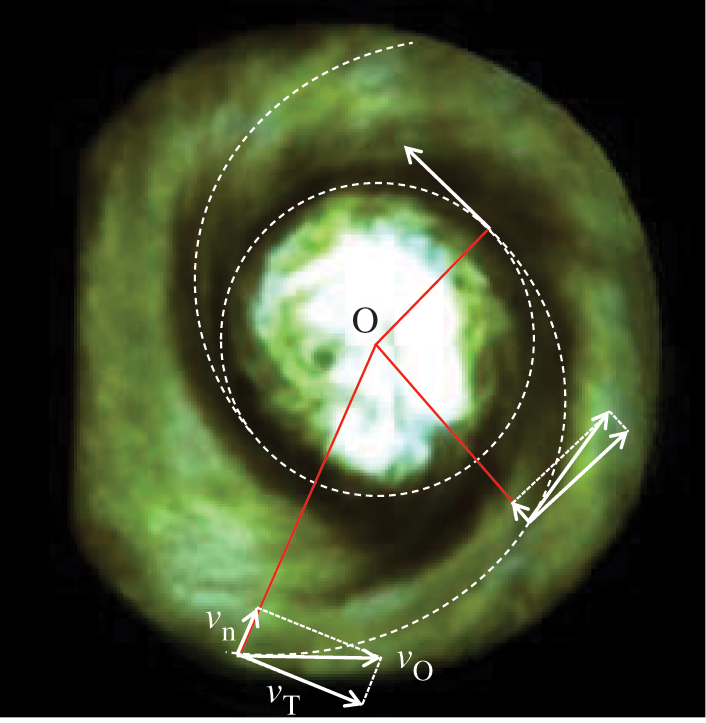
Figure 7: Diffusion path and spatial distribution of fuel vapor, image taken at t = 15.3 ms, pinj = 40 MPa
For the two sprays at two injection pressures of 60 MPa and 40 MPa, the higher-pressure injection got a higher diffusion area all the time and a shorter diffusion time than those of lower-pressure injection. This was resulted from the better atomization and the more fuel injection under higher injection pressure. Concerning the duration of each stage, the maintenance period of 40 MPa injection in stage (2) was longer than that of 60 MPa since the fuel film coating on the sidewall was thinner due to the less fuel injection. The fast diffusion stages of the two injection pressures, however, had almost the same durations, which were 4.20 ms for 60 MPa while 4.24 ms for 40 MPa. This phenomenon inferred that the fuel injection hardly influences the intensity of the swirl flow despite the value of injection pressure. As for the final diffusion stages, the 60 MPa injection had a similar trend with that of 40 MPa, and yet, a shorter duration. Since the backlight cannot passed through the fuel-air mixture when the fuel concentration reached a threshold, the sequential increase of fuel concentration would not be recognizable from the images; as a result, the shorter final diffusion duration of 60 MPa might not be the fact as it appears.
3.3 Spray Diffusion in Oblique Flow Field
The diffusion of diesel spray in the swirl field generated from the oblique flow performed much alike with that from tangential flow. As shown in Fig. 9, the diffusion process can also be divided into four stages. The spray was also bended by the swirl in the injection process; however, with shorter penetration distance and smaller diffusion area in contrast to that in tangential flow. The spray penetrated only a little more than half of the circle and left vast blank area between spray edge and sidewall. These were the result of smaller swirl ratio of oblique flow, as shown in Fig. 5, which was only about 1/3 of that of tangential flow.
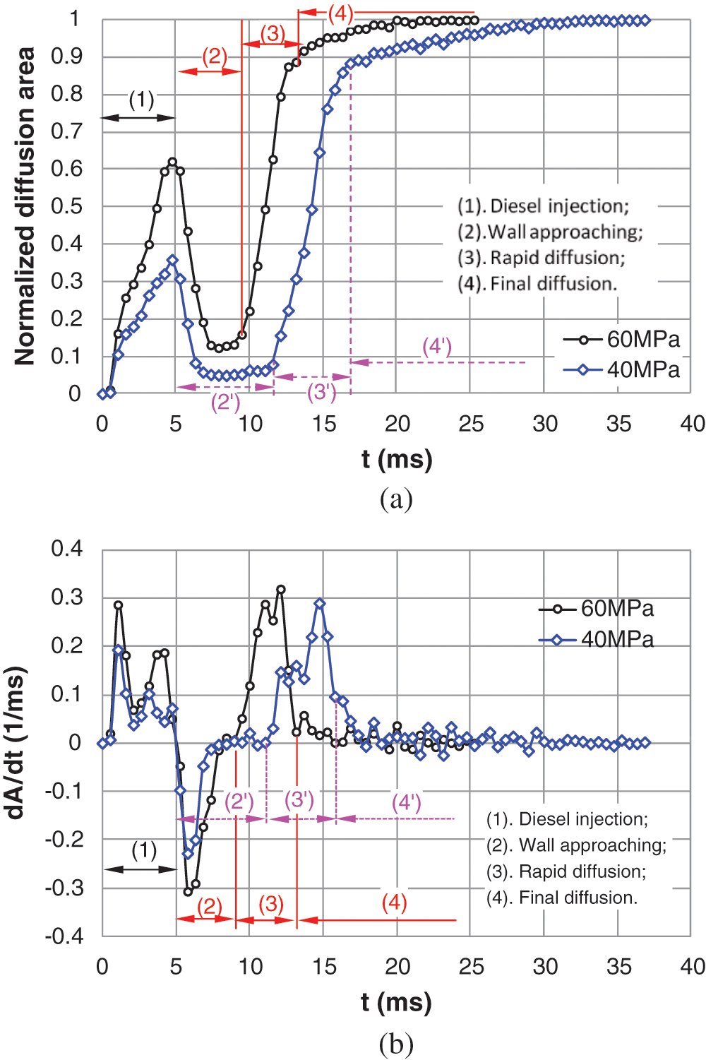
Figure 8: Development of normalized spray diffusion area and its increasing rate in tangential flow field. (a) Normalized diffusion area and (b) Increasing rate of diffusion area
The oblique flow blew down into the chamber with the angle of 65° with vertical line, as shown in Fig. 10, regardless of flow expansion and energy dissipation, only about 34.2% of the original velocity with 11.7% of total kinetic energy could be theoretically transformed to the tangential flow, most of the velocity and energy were converted to the centripetal flow. This resulted in a smaller “typhoon eye” and a stronger centripetal transportation of fuel, thus, the fuel vapor could be transported directly via the spiral arms into the swirl center. This was also confirmed by Dembinski’s simulation results [18], the centripetal velocity component promoted fuel delivered to the flow center.
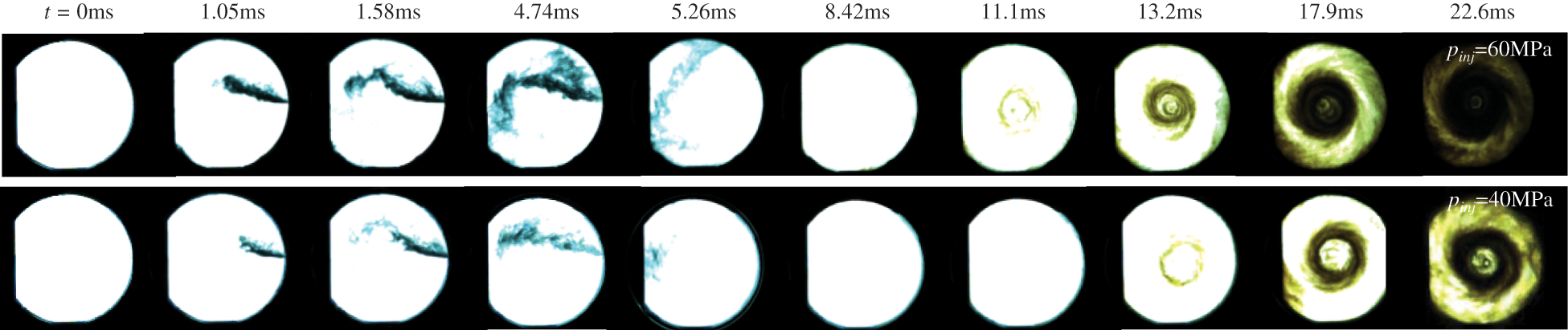
Figure 9: Evolution of diesel spray diffusion process in oblique flow swirl field
Fig. 11 shows the normalized diffusion area of the diesel spray in oblique flow caused swirl field. The diffusion area increased linearly for under both injection pressures, and the spray was driven on to the sidewall instantly within 0.5 ms at the end of injection. The coating processes of the 60 MPa and 40 MPa injections remained for 6.38 ms and 7.95 ms, respectively. Then the fuel vapor diffused towards the chamber center via the spiral arms with a quasi-constant speed of around 0.13 per microsecond for 60 MPa injection. The final diffusion process could hardly be seen due to the rapid diffusion in the smaller swirl center due to the lower rotating velocity and centrifugal force in contrast to those of tangential flow. The total diffusion duration lasted 22.5 ms and 29.5 ms for the injection pressures of 60 MPa and 40 MPa, respectively.
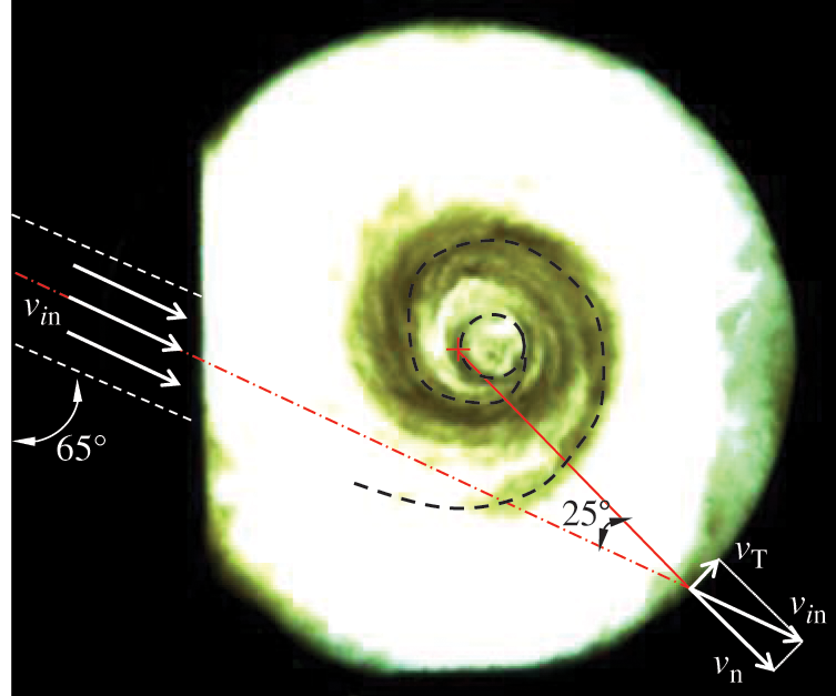
Figure 10: Diffusion path and spatial distribution of fuel vapor, image taken at t = 13.2 ms, pinj = 60 MPa
3.4 Spray Diffusion in Direct Flow Field
Fig. 12 shows the diffusion process of diesel spray in the flow field generated from direct flow. The situation varied from tangential and oblique flow field. When the air was blown into the chamber directly towards the chamber center, it rushed vertically onto the sidewall, forming a turbulent flow rather than a swirl flow. However, not all the kinetic energy of the air flow was converted into turbulent energy, a little part of that remains to form a swirl flow field with a much smaller swirl ratio compared with the other two swirl fields.
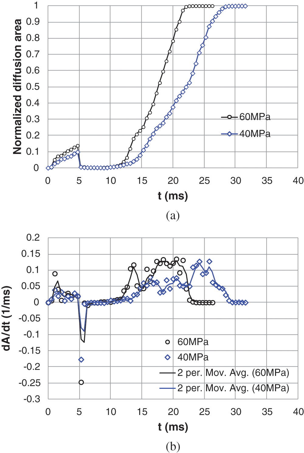
Figure 11: Development of normalized spray diffusion area and its increasing rate in oblique flow swirl field. (a) Normalized diffusion area and (b) Increasing rate of diffusion area
As a result, the diesel spray was not bended by the air flow as in the above two swirl fields; all the fuel in spray rushes directly onto the wall of the swirl block on the left, leaving the chamber blank as usual. Although the swirl flow was weak, the fuels succeed in coating the whole sidewall and diffused into the interspaces from the full circumference. The diffusion process was rather different from the above twos. Rather than transported from the spiral arms to form a “typhoon”, the fuel vapor might appear anywhere in the chamber interspaces, and fuel-rich districts grew and revolved around their own axis in random directions. Thus, the fuel vapor diffused in this turbulent field more homogenously than in the above two stratified swirl fields, where could be divided into fuel-rich and fuel-lean regions.
Fig. 13 shows the development of normalized diffusion area. The process could also be divided into four stages, however, the boundary between wall approaching and rapid diffusion was not so clear due to the low swirl ratio and strong turbulent. The diffusion time was also much longer than that in the swirl flows, thus with a lower diffusion rate, which were around 0.07 (1/ms) and 0.04 (1/ms) at most under 60 MPa and 40 MPa injection, respectively.
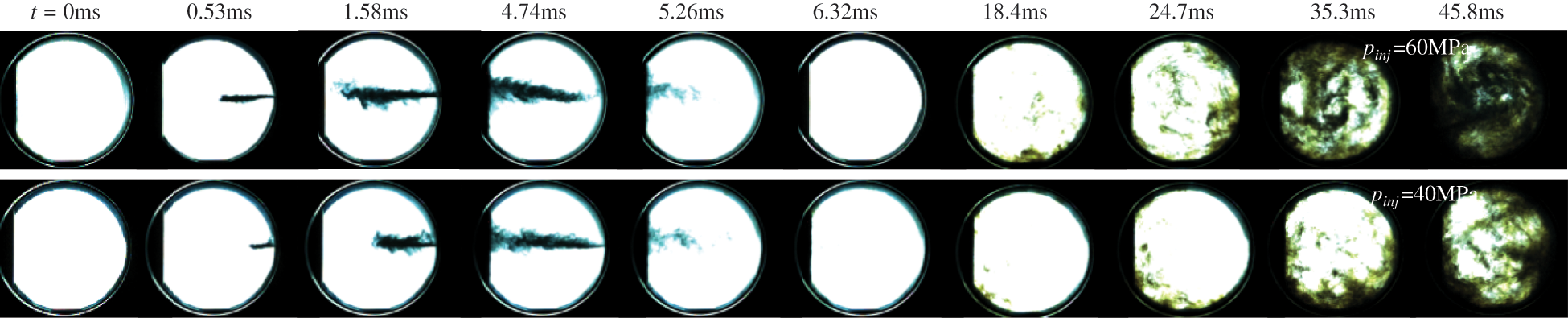
Figure 12: Evolution of diesel spray diffusion process in direct flow turbulent field
3.5 Comparison of Spray Diffusion in Three Flow Fields
Although the diffusion processes in different flow fields had many phenomenon in common, they differed much in details. As shown in Fig. 14a, the diffusion areas of tangential flow in the injection stage were much higher than in the other two flows. These were resulted by the stronger lateral wind in the tangential flow. The diffusion areas reached the maximum of 62% and 37.5% of chamber area for the injections under 60 MPa and 40 MPa, respectively. Since the outer layer flow velocities in the oblique flow and direct flow (turbulent field) fields failed to thoroughly scatter the main body of fuel spray, the spray areas were similar in these two fields and reach only a maximum of around 14.5% and 9%, respectively. As for the diffusion durations, a lower injection pressure and a weaker swirl ratio lead to a slower diffusion rate. The diffusion duration in the turbulent field was about 2.5 times of those in the tangential and oblique fields.
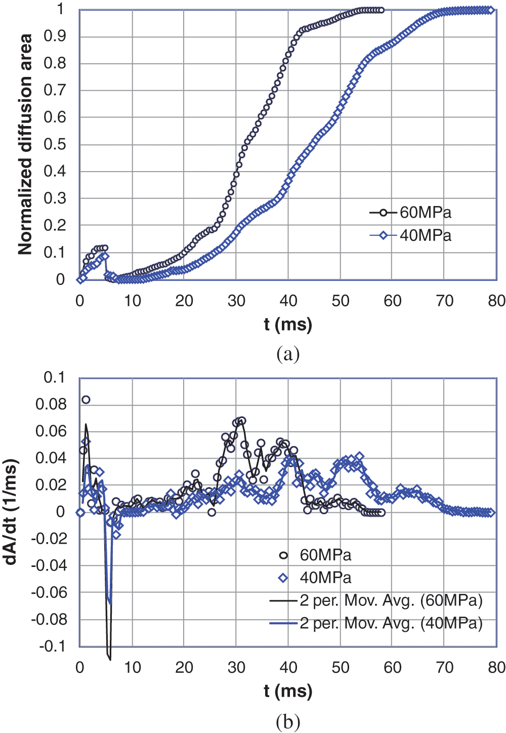
Figure 13: Development of normalized spray diffusion area and its increasing rate in direct flow turbulent field. (a) Normalized diffusion area and (b) Increasing rate of diffusion area
Since the diffusion process was determined by two parameters relating to air flow intensity and fuel flow velocity, thus taking 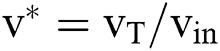 , where vT and vin, represent the tangential velocity and the initial air velocity shown as in Fig. 10; and
 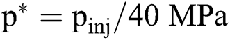 , with pinj denotes the fuel injection pressure, then correcting the x coordinate in Fig. 14a to
  , the diffusion curves will collapse down, as shown in Fig. 14b. This indicated that the diffusion of nonvolatile fuel in swirl flow quantitatively followed the rule of swirl intensity and fuel injection pressure.
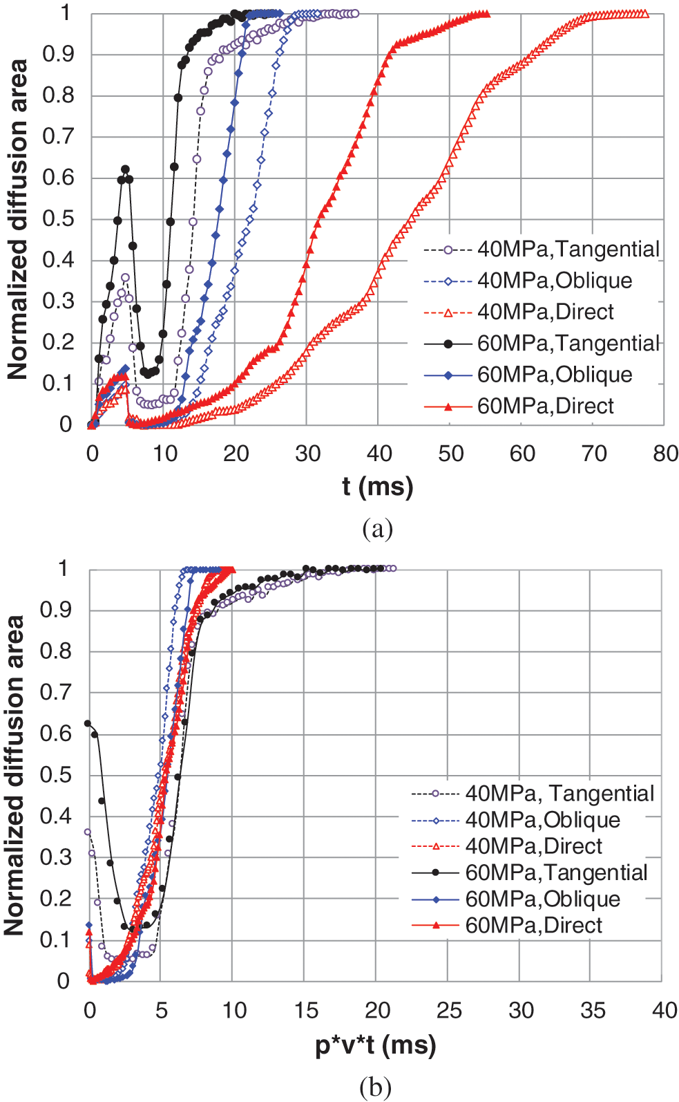
Figure 14: Comparison of spray diffusions in three flow fields under various injection pressures. (a) Spray diffusions in three flow fields and (b) Comparison under scaled time
In this paper, we created three kinds of flow fields in an optical RCM, observed the diffusion process of fuel spray in swirl flow, and studied the diffusion characteristics of fuel spray in intense swirl flow, weak swirl flow and turbulent flow. The highlighting conclusions were drawn as follows.
With the mean compression velocity of 7.55 m/s, the initial swirl ratio of 5.8, and compression pressure of 1.6 MPa, the present RCM system was suitable to simulate the swirl and pressure conditions in diesel chamber. The photographs recording the fuel spray diffusion process gave an intuitive observation and help better understanding of the spray and combustion process in diesel engine chamber where it was difficult to observe directly.
The process of fuel spray from injection to thorough mixing with swirl flow consisted of four stages: injection process, wall approaching stage, rapid diffusion stage and final diffusion stage.
The wall approaching stage included two sub-processes. The fuel spray was blown rapidly onto, and then coated, on the sidewall.
In the rapid diffusion stage, the fuel diffused from side wall to the plenum of the chamber in gaseous phase via mainly the route of spiral arms in the swirl filed, and then gathered forming a “typhoon” like fuel vapor cloud. The “typhoon” body grew rapidly with the continuous incoming of fuel vapor. A higher swirl ratio related to a larger “typhoon eye”.
The diffusion in turbulent flow field was different from that in the swirl fields; the fuel vapor could emerge unpredictably anywhere.
The diffusion was the result of fuel injection and air flow, correcting diffusion time to  may eliminate the influence of the flow type, flow intensity and fuel injection pressure, and made the diffusion rate as a function of
  .
.
Funding Statement: The work at Xi’an Jiaotong University was supported by the National Natural Science Foundation China (Nos. 51576159 and 91741110) and the Shaanxi Provincial Key R&D Plan (Grant Nos. 2019ZDLGY15-10 and 2019ZDLGY15-07).
Conflicts of Interest: The authors declare that they have no conflicts of interest to report regarding the present study.
References
1. Reitz, R. D. (2013). Directions in internal combustion engine research. Combustion and Flame, 160(1), 1–8. DOI 10.1016/j.combustflame.2012.11.002.
2. Musculus, M. P., Miles, P. C., Pickett, L. M. (2013). Conceptual models for partially premixed low-temperature diesel combustion. Progress in Energy and Combustion Science, 39(2–3), 246–283. DOI 10.1016/j.pecs.2012.09.001.
3. Desantes, J. M., Margot, X., Pastor, J. M., Chavez, M., Pinzello, A. (2009). CFD−phenomenological diesel spray analysis under evaporative conditions. Energy & Fuels, 23(8), 3919–3929. DOI 10.1021/ef9002999.
4. Pogorevc, P., Kegl, B., Skerget, L. (2008). Diesel and biodiesel fuel spray simulations. Energy & Fuels, 22(2), 1266–1274. DOI 10.1021/ef700544r.
5. Park, S. H., Kim, H. J., Lee, C. S. (2010). Numerical investigation of combustion and exhaust emissions characteristics based on experimental spray and atomization characteristics in a compression ignition diesel engine. Energy & Fuels, 24(4), 2429–2438. DOI 10.1021/ef901211d.
6. Kim, M. Y., Bang, S. H., Lee, C. S. (2007). Experimental investigation of spray and combustion characteristics of dimethyl ether in a common-rail diesel engine. Energy & Fuels, 21(2), 793–800. DOI 10.1021/ef060310o.
7. Kuti, O. B., Zhu, J. Y., Nishida, K., Wang, X. G., Huang, Z. H. (2012). Characterization of spray and combustion processes of biodiesel fuel injected by diesel engine common rail system (PDF). Fuel, 104, 838–846. DOI 10.1016/j.fuel.2012.05.014.
8. Gong, Y. Y., Li, X. G., Peng, Z. J. (1995). Droplet size distributions in diesel fuel sprays. Progress in Natural Science, 5(5), 632–637.
9. Kim, K., Chung, J., Lee, K. Y., Lee, K. (2008). Investigation of the swirl effect on diffusion flame in a direct-injection (DI) diesel engine using image processing technology. Energy & Fuels, 22(6), 3687–3694. DOI 10.1021/ef8003224.
10. Perini, F., Miles, P. C., Reitz, R. D. (2014). A comprehensive modeling study of in-cylinder fluid flows in a high-swirl, light-duty optical diesel engine. Computers & Fluids, 105, 113–124. DOI 10.1016/j.compfluid.2014.09.011.
11. Bohl, T., Tian, G., Zeng, W., He, X., Roskilly, A. (2014). Optical investigation on diesel engine fuelled by vegetable oils. Energy Procedia, 61, 670–674. DOI 10.1016/j.egypro.2014.11.939.
12. Dumitrescu, C. E., Mueller, C. J., Kurtz, E. (2016). Investigation of a tripropylene-glycol monomethyl ether and diesel blend for soot-free combustion in an optical direct-injection diesel engine. Applied Thermal Engineering, 101, 639–646. DOI 10.1016/j.applthermaleng.2015.12.068.
13. Jeon, J., Lee, J. T., Kwon, S. I., Park, S. (2016). Combustion performance, flame, and soot characteristics of gasoline–diesel pre-blended fuel in an optical compression-ignition engine. Energy Conversion and Management, 116, 174–183. DOI 10.1016/j.enconman.2016.03.003.
14. Catapano, F., Sementa, P., Vaglieco, B. M. (2016). Air-fuel mixing and combustion behavior of gasoline-ethanol blends in a GDI wall-guided turbocharged multi-cylinder optical engine. Renewable Energy, 96, 319–332. DOI 10.1016/j.renene.2016.04.087.
15. Wei, S., Wang, F., Leng, X. (2013). Numerical analysis on the effect of swirl ratios on swirl chamber combustion system of DI diesel engines. Energy Conversion and Management, 75, 184–190. DOI 10.1016/j.enconman.2013.05.044.
16. Zhou, H., Li, X., Zhao, W., Zhao, W., Liu, F. (2019). Effects of separated swirl combustion chamber geometries on the combustion and emission characteristics of DI diesel engines. Fuel, 253, 488–500. DOI 10.1016/j.fuel.2019.05.032.
17. Wang, G., Yu, W., Li, X., Su, Y., Yang, R. et al. (2019). Experimental and numerical study on the influence of intake swirl on fuel spray and in-cylinder combustion characteristics on large bore diesel engine. Fuel, 237, 209–221. DOI 10.1016/j.fuel.2018.09.156.
18. Dembinski, H. W. (2014). The effects of injection pressure and swirl on in-cylinder flow pattern and combustion in a compression–ignition engine. International Journal of Engine Research, 15(4), 444–459. DOI 10.1177/1468087413491262.
19. Su, L., Li, X., He, X., Liu, F. (2015). Experimental research on the diffusion flame formation and combustion performance of forced swirl combustion system for DI diesel engines. Energy Conversion and Management, 106, 826–834. DOI 10.1016/j.enconman.2015.10.027.
20. Benajes, J., Molina, S., García, J. M. (2016). The effect of swirl on combustion and exhaust emissions in heavy-duty diesel engines. Proceedings of the Institution of Mechanical Engineers, Part D: Journal of Automobile Engineering, 218(10), 1141–1148. DOI 10.1177/095440700421801009.
21. Guibert, P., Keromnes, A., Legros, G. (2008). An experimental investigation of the turbulence effect on the combustion propagation in a rapid compression machine. Flow Turbulence & Combustion, 84(1), 79–95.
22. Strozzi, C., Mura, A., Sotton, J., Bellenoue, M. (2012). Experimental analysis of propagation regimes during the autoignition of a fully premixed methane–air mixture in the presence of temperature inhomogeneities. Combustion and Flame, 159(11), 3323–3341. DOI 10.1016/j.combustflame.2012.06.011.
23. Yu, L., Wu, Z., Qiu, Y., Yong, M., Lu, X. (2018). Ignition delay times of decalin over low-to-intermediate temperature ranges: rapid compression machine measurement and modeling study. Combustion and Flame, 196, 160–173. DOI 10.1016/j.combustflame.2018.06.014.
24. Wadkar, C., Chinnathambi, P., Toulson, E. (2019). Analysis of rapid compression machine facility effects on the auto-ignition of ethanol. Fuel, 264, 116546. DOI 10.1016/j.fuel.2019.116546.
25. Wei, H., Hu, Z., Pan, J., Wang, X. W. (2019). Effect of fuel properties on knocking combustion in an optical rapid compression machine. Energy & Fuels, 33(12), 12714–12722. DOI 10.1021/acs.energyfuels.9b02166.
26. Lee, S., Song, S. (2020). A rapid compression machine study of hydrogen effects on the ignition delay times of n-butane at low-to-intermediate temperatures. Fuel, 266, 116895. DOI 10.1016/j.fuel.2019.116895.
27. Mittal, G., Sung, C. J. (2006). Aerodynamics inside a rapid compression machine. Combustion and Flame, 145(1–2), 160–180. DOI 10.1016/j.combustflame.2005.10.019.
28. Wu, Y., Yang, M., Tang, C., Liu, Y., Zhang, P. et al. (2019). Promoting “adiabatic core” approximation in a rapid compression machine by an optimized creviced piston design. Fuel, 251, 328–340. DOI 10.1016/j.fuel.2019.04.030.
 | This work is licensed under a Creative Commons Attribution 4.0 International License, which permits unrestricted use, distribution, and reproduction in any medium, provided the original work is properly cited. |