DOI:10.32604/EE.2020.013349
| Energy Engineering DOI:10.32604/EE.2020.013349 | |
| Article |
Experimental Investigation of Flame Structure and Combustion Limit During Premixed Methane/Air Jet Flame and Sidewall Interaction
School of Energy and Power Engineering, Jiangsu University, Zhenjiang, 212013, China
*Corresponding Author: Jianfeng Pan. Email: mike@ujs.edu.cn
Received: 03 August 2020; Accepted: 24 August 2020
Abstract: The effects of inlet gas parameters and sloping sidewall angle on the flame structure and combustion limit with and without sidewall were experimentally investigated. Flame height and impact angle were obtained by chemiluminescence intensity analysis of CH* distribution. First, the combustion characteristics of flame with and without sidewall at different equivalence ratios were explored; then, the influence of Reynolds number and inlet gas temperature on flame structure and combustion limit of v-shaped flame with sidewall were analyzed, and the results with sidewall were compared with those without sidewall. Finally, the variation trend of flame parameters with different sloping sidewall angles was analyzed. The experimental results show that the existence of sidewall makes flame shape change from “M-shaped” to “inverted N-shaped”, and conical shape to trapezoidal shape. The inhibition effect of sidewall on flame stretching downstream is strengthened with the increase in Reynolds number; but as the temperature of the inlet gas increases, the inhibitory effect is obviously weakened. When sloping sidewall angle decreases from 90° to 55° at 5° intervals, flame height and impact angle of v-shaped flame reach the extreme value when β = 80°. Compared with the case without sidewall, the range of v-shaped flame with sidewall has no obvious trend of broadening or shrinking when inlet gas temperature is increased; however, as sloping sidewall angle decreases, the range of the v-shaped flame shrinks obviously and flammability limit increases significantly.
Keywords: Sidewall; premixed flame; flame-wall interaction; flame structure; combustion limit
Flame-wall interaction exists widely in combustion processes, such as combustion in internal-combustion engine [1–4], catalytically assisted combustion [5–7] and micro scale combustion [8–11]. The presence of the wall has an important influence on the thermodynamics, flow and reaction dynamics of the flame [12]. The temperature of the wall is much lower than that of the flame, so when the flame is close to the wall, it will produce a high heat flux, which leads to local quenching, that results in bad combustion phenomenon, thereby increasing the amount of generated pollutants and heat loss. Therefore, the study of flame-wall interaction is of great importance in the design of actual combustion device and the improvement of combustion process.
Flame-wall interaction can be divided into head-on interaction [13–17] and sidewall interaction. In head-on interaction, the whole flame contacts the top wall, while in sidewall interaction, only one or two flame branches close to the sidewall are in contact with the sidewall. The concept of sidewall interaction was proposed by Alshaalan et al. [18] when DNS was used to study the influence of the wall on thickness and length of turbulent flame, the typical configuration of which was a v-shaped flame. Ganter et al. [19,20] evaluated the prediction accuracy of temperature and carbon monoxide concentration near the sidewall by different chemical pre-tabulation and compared them with the experimental results. The results show that the real dissipation rate of carbon monoxide can be obtained without prior knowledge by building reaction-diffusion-manifold (REDIM) based on one-dimensional detailed chemical reaction simulation results; subsequent simulation by Fastest shows that the high concentration of carbon monoxide near the wall is caused by the migration of carbon monoxide produced at a distance from the wall. Andrae et al. [21] declared through two-dimensional detailed chemical simulation that when there is a cooling wall, there is a main pollutant emission near the wall which is the intermediate hydrocarbon; the boundary layer of stoichiometric flame is thicker than that of lean flame, and the flame with equivalence ratio of 1.0 needs longer residence time when it burns in the boundary layer than that of lean flame.
Taybi et al. [22] and Vean et al. [23] studied the flame surface density and heat flow density at the front of turbulent flame. The experimental results show that the maximum value of flame surface density increases with the decrease of flame wrinkle, and the maximum heat flow in the flame-wall coupling region is up to 11 kw/m2. Kosaka et al. [24] compared the formation and oxidation processes of carbon monoxide in laminar flame and turbulent flame based on the experimental method of laser diagnosis. They found that, compared with laminar flame, the branch of carbon monoxide generated in turbulent flame is less affected, and the branch of carbon monoxide oxidation will move to a lower temperature throughout the near wall region. Based on the same experimental setup, Jainski et al. [25,26] studied the heat flux on the wall and the characteristics of flame velocity, flame surface density, average reaction rate and gas temperature near the wall. Due to the local quenching of the sidewall, the average reaction rate of the flame-wall coupling region decreases and tends to zero very close to the wall, which is considered to be related to the increase in flame surface density.
In addition to combustion characteristics, flame structure is also a focus of research on flame-wall interaction. Häber et al. [27] and Saffman et al. [28] studied the quenching distance corresponding to different wall materials, thermal insulation coating and fuel. The experimental results indicate that the quenching distance depends on stoichiometric ratio and fuel type to a great extent, and the effect of the thermal insulation coating and the wall material on quenching is quite small. Heinrich et al. [29] used a combination of large eddy simulation (LES) and experiment to compare the characteristic parameters of the flame structure of laminar and turbulent flames. The results make it clear that the length of turbulent flame is significantly longer than that of laminar flame; the impact angle of turbulent flame will fluctuate in a large range, even reaching a negative value, while the impact angle of laminar flame is small and remains unchanged; the quenching point of laminar flame coincides with the point of maximum heat flux near the wall, and the quenching point of turbulent flame is upstream of the point of maximum heat flux. Tang et al. [30] studied the flame height and the heat flux of the wall at different sloping wall angles, and gave a general correlation formula.
The research on the interaction between the flame and the sidewall is mainly divided into two aspects. The first aspect is to pay attention to the combustion characteristics of the flame with a sidewall. The simulation study mainly explores the numerical calculation model which is more suitable for flame-wall interaction while the experimental research is mainly about using advanced laser diagnostic instruments to measure the generation of pollutants such as carbon monoxide near the wall under different operating conditions, as well as the development trend of heat transfer characteristics such as temperature and heat flux near the wall. The other aspect is to study the characteristic parameters of flame structure such as quenching distance, quenching height and impact angle of v-shaped flame under different wall materials and fuels. The above researches focus on the influence of the sidewall on various flame parameters. However, there is little research on the difference between flame parameters with and without the sidewall. In this paper, the flame structure and combustion limit corresponding to different inlet premixed gas parameters and sloping sidewall angles with and without the sidewall are compared for the first time. This enriches the combustion theory and lays a foundation for further study of the interaction mechanism between the flame and the wall, which helps to improve the performance of various combustion devices and achieve long-term stable operation.
The experimental setup includes a square tube jet burner, a stainless-steel wall, a circular ceramic rod, a digital camera, flowmeters and gas heating device. The experiment was conducted at atmospheric pressure. Methane and air mass flowmeters were used to control the parameters of gas intake. The range of methane mass flowmeter is 0–300 ml/min and the range of air mass flowmeter is 0–3000 ml/min; both flowmeters have an accuracy of 1%. The fully premixed gas of methane and dry air heated to the specified temperature by the gas heating device was ignited at the burner outlet, the circular ceramic rod (Ф1 mm) at a distance of 2 mm above the burner outlet stabilized the two branches of the flame, then the branch near the wall contacted with the wall, which resulted in the change of flame parameters such as the flame shape, flame height, and combustion limit. A digital camera (PENTAX K-50) was used to capture the flame shape, with a maximum pixel of 16.49 million. The CH* filter installed in front of the lens of a digital camera was used to capture the distribution of CH* in flame. The center wavelength of the CH* filter is 430 nm, the bandwidth is 30 nm, and the cut-off depth is od2-od3.
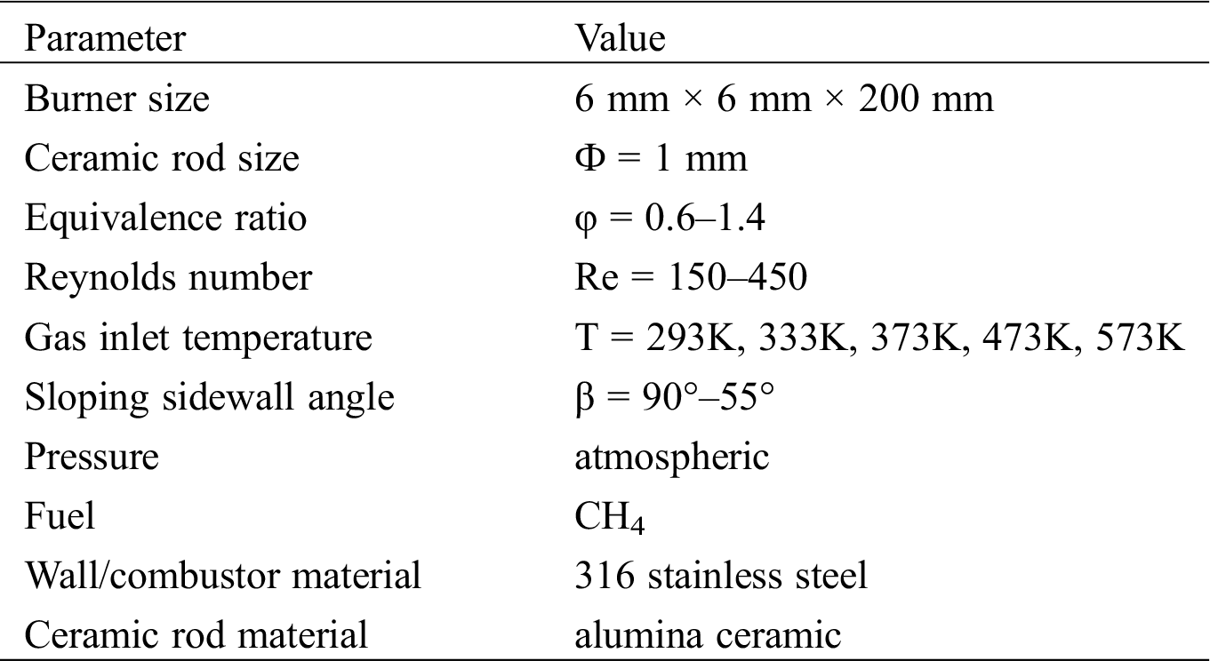
The gas heating device consists of silicon nitride heating plates, a voltage regulator and a K-type thermocouple. 220 V AC was connected to the voltage regulator with the range of 0–250 V, and the output voltage is directly proportional to the heating power. The premixed gas was heated by heating plates whose heat load can reach 25 W/cm2 and surface temperature can reach 1200°C. At the same time, the K-type thermocouple with a measurement range of −173K ~ +2273K and an accuracy of 0.2% was placed above the burner outlet to measure the temperature of premixed gas. As long as the temperature of the premixed gas reached the specified value, it would be ignited. The experimental setup is shown in Fig. 1. The operating conditions of the burner are shown in Tab. 1.
Figure 1: Schematic diagram of the experimental setup and the burner with different fields of view. (a: schematic diagram of the experimental setup; b: front view of the burner; c: top view of the burner. The flame height is represented by the character H, the impact angle is represented by the character α, and the sloping sidewall angle is represented by β)
Table 1: Operating conditions of the burner
3.1 Effect of Equivalence Ratio
Fig. 2 shows the flame shape with and without the sidewall when the Reynolds number (Re) is 300 and the inlet gas temperature is 293K. In this paper, only the shape of inner flame is considered and the situation of outer flame is not discussed. In the range where the equivalent ratio φ is less than 0.5, the premixed gas is too thin to ignite. When the equivalence ratio is between 0.6 and 0.7, both the flame, with and without the sidewall, are v-shaped and stabilized above the circular ceramic rod. In the process of increasing the equivalence ratio from 0.8 to 1.0, the premixed gas burns more completely, which leads to a decrease in the flame height, and the branch of v-shaped flame falls on the exit plane of burner. When the equivalence ratio is between 0.8 and 1.2, both branches of v-shaped flame without the sidewall fall on the exit plane of the burner, and the flame is “m-shaped”. In the case of a sidewall, the flow field near the left branch of the flame is affected by the wall, causing a change in the flame shape. The left branch of the flame adheres to the sidewall and the right branch of the flame falls on the exit plane of the burner, so the flame appears as “Inverted N-shaped”. When the equivalence ratio is greater than 1.4, the flame bypasses the ceramic rod and continues to propagate downstream. Without a sidewall, the shape of the flame is “conical”; with a sidewall, the flame completely adheres to the sidewall, and the shape is “trapezoidal”. It can be seen that the sidewall has a significant influence on the flame shape corresponding to different equivalent ratios.
Figure 2: Flame shape at different equivalence ratio (a: flame images with the sidewall. b: flame images with the sidewall after chromatic aberration analysis. a: flame images without the sidewall. b: flame images without the sidewall after chromatic aberration analysis. The Reynolds number of the premixed gas is 300)
As shown in Fig. 2, the inner flames of M-shaped, inverted N-shaped, cone-shaped and trapezoidal flames all have bright edges, so the flame profile can be directly extracted from the image. However, the V-shaped flame does not have a clear flame edge, therefore, the distribution of CH* in the V-shaped flame is used to characterize the flame shape. In order to further analyze the flame profile, the chemiluminescence intensity distribution of CH* in flame is analyzed [30], as shown in Fig. 3. The flame profile is fixed on the contour line where the chemiluminescent intensity is reduced to 50% of its maximum value. The flame height H is defined as the distance between the highest point of the profile on the left branch in flame and the exit plane of the square tube burner. Impact angle α is defined as the angle between the profile of the flame on the left branch and the sidewall, and the impact angle without the sidewall is defined as the angle between the profile of the flame on the left branch and the vertical plane.
Figure 3: Distribution and chemiluminescence intensity of CH* (left: distribution of CH* in flame, right: chemiluminescence intensity of CH*)
When the Reynolds number is 300 and the inlet gas temperature is 293K, the changes in flame height and impact angle corresponding to different equivalence ratio with the sidewall and without the sidewall are shown in Fig. 4. When the equivalence ratio is between 0.6 and 0.75, the shapes of the flame with the sidewall and the flame without the sidewall are always v-shaped and the flame heights of both decrease with the increase in the equivalence ratio. The flame height without the sidewall is higher than that with the sidewall, which means that the sidewall restrains the stretch of v-shaped flame to the downstream. When the equivalence ratio is greater than 0.75, the flame height decreases first and then increases with the increase in equivalence ratio, then reaches the minimum value when the equivalence ratio is 1.0. The flame height without the sidewall is always lower than the value with the sidewall, and as the equivalence ratio increases, the difference between the flame height with the sidewall and the flame height without the sidewall increases, which indicates that the influence of the sidewall on the flame height is strengthened. When the equivalence ratio is less than 1.2, the impact angle increases first and then decreases with the increase in equivalence ratio, and reaches the maximum value when the equivalence ratio is 1.0. In the range where the equivalence ratio is greater than 1.2, the impact angle without the sidewall increases rapidly with the increase in the equivalence ratio, while the impact angle with the sidewall decreases slowly with the increase in the equivalence ratio.
Figure 4: Flame height and impact angle of the cases with and without the sidewall at different equivalence ratio (the Reynolds number corresponding to each point in the figure is 300)
Since the typical configuration of flame and sidewall interaction is v-shaped flame, the combustion characteristics of v-shaped flame are analyzed in detail below. Fig. 5 shows the distribution of flame height and impact angle at different Reynolds numbers with and without the sidewall when the equivalence ratios φ are 0.6 and 0.7 and the inlet gas temperature is 293K. When the equivalence ratios are 0.6 and 0.7, the impact angles with and without the sidewall decrease with the increase in Reynolds number, and the impact angle without the sidewall is always larger than that with the sidewall. As the Reynolds number increases, the flame propagation speed and the flow rate of the unburned gas mixture increase, so the flame height increases both with and without the sidewall. The flame height without the sidewall is always higher than that with the sidewall, which again verifies that the sidewall can restrain the V-shaped flame from stretching downstream. When the Reynolds number are respectively 200, 300, 400, 450 and the equivalence ratio is 0.6, the difference in flame height values with and without the sidewall are respectively 1.5 mm, 2.6 mm, 3.5 mm, 4.4 mm; when the Reynolds number are respectively 200, 300, 400, 450 and the equivalence ratio is 0.7, the difference in flame height values with and without the sidewall are respectively 0.4 mm, 1.9 mm, 2.0 mm, 4.0 mm. which shows that with the increase in Reynolds number, the inhibition of the sidewall on the flame height is strengthened.
Figure 5: Flame height and impact angle with different Reynolds numbers
In the experiment, the Reynolds number of the premixed gas at the jet outlet constant was kept unchanged, the flow of methane was gradually reduced, at the same time, the flow of dry air was increased. The minimum equivalent ratio of the flame which could burn stably on the ceramic rod was recorded as the flammability limit of the flame. When the equivalence ratio is lower than the flammability limit, the premixed gas cannot be ignited. The flame maintains stable combustion when the equivalence ratio is higher than the flammability limit. The flammability limits with and without the sidewall at different Reynolds numbers are shown in Fig. 6. Increasing the Reynolds number have two effects on the flammability limit. On one hand, with the increase of methane flow rate, the heat generated by the combustion of premixed gas will increase, it is easy to maintain stabilized combustion of the flame, therefore the flammability limit will decrease; on the other hand, the increase in Reynolds number makes the flame height higher, so the area of the flame surface contacting with the environment is larger. The heat loss due to the heat exchange between the flame and the environment increases, remain stabilized combustion for the flame is more difficult to realize, therefore the flammability limit increases. At 150 < Re < 250, the flammability limit increases with the increase in Reynolds number, which is due to the more obvious effect of heat loss between flame and environment; At 250 < Re < 450, the flammability limit decreases with the increase in Reynolds number. This is because the effect of heat generated by the increase of methane flow rate is more obvious as the Reynolds number increases. At the same Reynolds number, the flammability limit for the case with the sidewall is always greater than that without the sidewall, because the convection heat loss between the flame and the sidewall is greater than that between the flame and the air.
Figure 6: Flammability limit with the sidewall and without the sidewall (the inlet gas temperature is 293k)
The range of the v-shaped flame with and without the sidewall is shown in Fig. 7. The lower combustion limit of the v-shaped flame is also the flammability limit. With the increase in Reynolds number, the lower combustion limit first increases and then decreases, and the lower combustion limit of the v-shaped flame with the sidewall is higher than that without the sidewall; The upper combustion limit of the v-shaped flame refers to the equivalent ratio when the v-shaped flame changes into an m-shaped or inverted N-shaped flame, which increases as the Reynolds number increases. This is because with the increase in Reynolds number, the flame height increases, resulting in increased heat dissipation loss of the flame surface, so the branch of the v-shaped flame is more difficult to fall on the exit plane of burner; and the upper combustion limit of the v-shaped flame with the sidewall is higher than that without the sidewall due to the heat loss of the sidewall. At 150 < Re < 250, the increasing value of the upper combustion limit of v-shaped flame is always greater than that of the lower combustion limit. Therefore, with the increase in Reynolds number, the range of the v-shaped flame expands continuously, but the range of v-shaped flame with and without the sidewall changes little.
Figure 7: Range of v-shaped flame with and without the sidewall (the inlet gas temperature is 293k)
3.3 Effect of Inlet Premixed Gas Temperature
Korolchenko et al. [31] and Michaels et al. [32] showed that as the temperature of the inlet gas increases, the combustion speed of methane/hydrogen flame increases, the combustible range of the flame is significantly widened, and the flame stability improves. However, the research on the difference of flame combustion characteristics with and without wall at different inlet gas temperatures remains to be perfected. During the experiment, the equivalence ratio of premixed gas is maintained at 0.6 and the Reynolds number is 300. The flame height and impact angle with and without the sidewall corresponding to different inlet gas temperatures are shown in Fig. 8. The higher the temperature of the inlet gas, the lower the height of the v-shaped flame. This is because the increase of inlet gas temperature leads to the increase of chemical reaction rate during combustion, which further causes the flame combustion and propagation speed to continue to increase, and therefore the flame height decreases. At different inlet gas temperatures, the flame height without the sidewall is always higher than that with the sidewall, which proves once again that the sidewall can inhibit the flame stretching downstream. When the inlet gas temperature is 293K, 373K, 473K, 573K, the difference in flame height with and without the sidewall is 1.4 mm, 0.8 mm, 0.6 mm and 0.4 mm. The results show that as the temperature of the inlet gas increases, the inhibitory effect of the sidewall on the flame stretching downstream is obviously weakened. It can be seen from Fig. 8 that when the inlet gas temperature is 293K, 373K, 473K, 573K, the difference of impact angle with and without the sidewall is 11°, 14°, 16°, 17°, which increases slightly with the increase of inlet gas temperature.
Figure 8: Flame height and impact angle at different inlet gas temperatures (the equivalence ratio of each point in the figure is 0.6, and the Reynolds number is 300)
As shown in Fig. 9, regardless of whether it is with or without the sidewall, increasing the inlet gas temperature will reduce the flammability limit of the v-shaped flame. This shows that increasing the inlet gas temperature can significantly extend the flammability limit of the flame, and it is an effective way to improve the combustion process and increase the stability of combustion. When the inlet gas temperature is heated from 293K to 373K, 373K to 473K, 473K to 573K, the difference between the flammability limits of v-shaped flames with and without the sidewall is increasing, respectively 0.008, 0.014, 0.016, 0.019. This is because by increasing the inlet gas temperature, the premixed gas will burn more fully, and the more heat will be released by the combustion. As a result, the temperature difference between the flame and the sidewall increases, and the heat exchange between the two increases, so the sidewall has a more obvious cooling effect on the v-shaped flame.
Figure 9: Flammability limit of v-shaped flame with and without the sidewall at different inlet gas temperatures
Fig. 10 shows the range of the v-shaped flame with and without the sidewall at different inlet gas temperatures. Increasing the inlet gas temperature, both the lower combustion limit and the upper combustion limit of the v-shaped flame move toward the lower equivalence ratio. The lower combustion limit of the v-shaped flame is significantly reduced, so the premixed gas is easier to ignite. At the same time, the upper combustion limit of the v-shaped flame also decreases significantly with the increase of the inlet gas temperature, which may be because as the temperature of the inlet gas rises, the combustion intensity is strengthened and the heat released by combustion increases, so the branches of the v-shaped flame are more likely to fall on the exit plane of the burner. When there is no sidewall, an M-shaped flame is formed. When there is a sidewall, an inverted N-shaped flame is formed. When the Reynolds number is 300 and the inlet gas temperature increases from 293K to 373K, 373K to 473K, 473K to 573K, the difference between the range of the v-shaped flame with and without the sidewall is small, and the difference is respectively 0.004, −0.001, 0, 0.005. It can be seen that when the inlet temperature increases, the sidewall has a very weak influence on the range of the v-shaped flame, and the range of the v-shaped flame has no obvious trend of broadening or shrinking.
Figure 10: Range of the v-shaped flame with and without the sidewall at different inlet gas temperatures. (a) T = 293K, (b) T = 373K, (c) T = 473K and (d) T = 573K
3.4 Effect of Sloping Sidewall Angle
In practical combustion equipment, there is usually an angle between the flame and the combustion chamber, which constitutes a special constraint boundary condition. The chamber is simplified as a sloping sidewall, keeping the position of the ceramic rod unchanged, and gradually reducing the sloping sidewall angle, the constraint effect will alter with the change of the sloping sidewall angle. The sloping sidewall angle β is defined as the angle between the sidewall and the exit plane of the burner. Fig. 11 shows the flame shape corresponding to different sloping sidewall angles when the equivalence ratio is 0.7 and the Reynolds number is 300. When the sloping sidewall angle β reduces from 90° to 55°, the amount of dry air entrained into the combustion area decreases, the combustion of the mixture becomes more complete and the flame becomes brighter gradually; The branch of the flame on the left side is obviously affected by the sidewall, and the length of the flame profile is significantly shorter; the branch of the flame on the right side is less affected by the sidewall, and the length of the profile has no obvious change. In general, the shape of the flame has not changed, it is still a v-shaped flame.
Figure 11: Flame shape with different sloping sidewall angles (the inlet gas temperature is 293K)
Fig. 12 shows the height and impact angle of the v-shaped flame corresponding to different sloping sidewall angles. When the sloping sidewall angle decreases from 90° to 80°, the impact angle decreases gradually and reaches the minimum value at β = 80°. Meanwhile, the flame height increases gradually and reaches the maximum value at β = 80°, which indicates that a larger sloping sidewall angle is conducive for the downstream stretching of the v-shaped flame. When the sloping sidewall angle decreases from 80° to 55° at 5° intervals, the rising values of the impact angle are 9°, 2°, 1°, 0.5° and 0.5° respectively. The rising values indicate that the impact angle first rises rapidly and then rises slowly. At the same time, the decreasing values of the flame height are 1.7 mm, 0.7 mm, 0.3 mm, 0.3 mm and 0.2 mm respectively. The flame height first declines rapidly and then slowly with the decrease in the sloping sidewall angle. The results show that when the sloping sidewall angle is less than 80°, the sidewall obstructs the v-shaped flame from stretching downstream, but the effect of the obstruction declines with the decrease in the sloping sidewall angle.
Figure 12: Flame height and impact angle corresponding to different sloping sidewall angles (the equivalence ratio of each point in the figure is 0.7, the Reynolds number is 300 and the inlet gas temperature is 293k)
The flammability limits corresponding to different sloping sidewall angles are shown in Fig. 13. When the sloping sidewall angle is the same, the flammability limit increases first, then decreases with the increase in Reynolds number. The smaller the sloping sidewall angle, the more difficult it is for the premixed gas to ignite and the flame to maintain stable combustion. The reason is that reduction of the sloping sidewall angle results in the smaller the distance between the flame and the sidewall, which increases the heat exchange loss between the flame and the sidewall. At the same Reynolds number, the flammability limit increases with the decrease in the sloping sidewall angle. When the Reynolds number is 250, the sloping sidewall decreases from 90° to 60° at 10° intervals, the flammability limits are 0.576, 0.606, 0.652 and 0.707 respectively, and the different values of the flammability limits are 0.03, 0.046 and 0.055, which shows that the influence of the sidewall on the flammability limit of the flame is gradually strengthened.
Figure 13: Flammability limit at different sloping sidewall angles (the inlet gas temperature is 293K)
Fig. 14 shows the range of the v-shaped flame corresponding to different sloping sidewall angles. As the sloping sidewall decreases, the distance between the sidewall and the flame decreases, the heat loss due to heat exchange between the flame and the sidewall increases, so the flame is easier to extinguish, the lower combustion limit of the v-shaped flame corresponding to different sloping sidewall angles increases, and the extinction range of the flame widens gradually. The upper combustion limit of the v-shaped flame decreases with the decrease in the sloping sidewall angle, which is due to the reduction of air volume in the environment that is sucked into the combustion area, so the combustion of premixed gas is more sufficient, and the branch of the v-shaped flame is more likely to fall on the plane of the burner to form an inverted N-shaped flame. At 150 < Re < 450, with the increase in Reynolds number, the range of the v-shaped flame corresponding to different sloping sidewall angles is widening; With the decrease in the sloping sidewall angle, the range of the v-shaped flame shrinks continuously. When the Reynolds number is 250 and the sloping sidewall angle is 60°, the upper combustion limit of the v-shaped flame coincides with the lower combustion limit of the v-shaped flame, and after the mixture is ignited, the v-shaped flame is no longer formed, but directly forms an inverted N-shaped flame over the ceramic rod.
Figure 14: Range of the v-shaped flame with different sloping sidewall angles (the inlet gas temperature is 293K). (a) β = 90° (b) β = 80°, (c) β = 70° and (d) β = 60°
In this paper, the flame shape, flame height, impact angle and combustion limit of CH4/Air premixed jet flame with and without the sidewall were studied by experiment. Compared with the case of no sidewall, the effects of the sidewall on premixed jet flame with different equivalence ratio, Reynolds number and inlet gas temperature were analyzed; and the combustion characteristics of the premixed jet flame with different sloping sidewall angles were also discussed.
The main results are summarized as follows:
1. When Reynolds number is 300 and equivalence ratio is from 0.6 to 1.5, the flame shape, flame height and impact angle are significantly affected by the presence of the sidewall; there are three kinds of flame shapes: v-shaped, m-shaped and cone-shaped when there is no sidewall; when there is a sidewall, “M-shaped” changes to “inverted N-shaped” and the conical shape changes to trapezoidal shape.
2. The downstream stretching of the v-shaped flame is restrained by the sidewall. With the increase in Reynolds number, the inhibition effect of the sidewall on the flame stretching downstream is strengthened; but as the temperature of the inlet gas increases, the inhibitory effect is obviously weakened.
3. The impact angle of the v-shaped flame with the sidewall is always lower than that without the sidewall, and the difference between them changes little with the increase in Reynolds number and inlet gas temperature.
4. The presence of the sidewall makes the flammability limit of the flame slightly increase, and has little effect on the range of the v-shaped flame; increasing the inlet gas temperature, the lower and the upper combustion limit of the v-shaped flame move to a lower equivalence ratio, but the range of the v-shaped flame has no obvious trend of broadening or shrinking; as the sloping sidewall angle decreases, the flammability limit increases significantly and the range of the v-shaped flame shrinks obviously.
5. When the sloping sidewall angle decreases from 90° to 55° at 5° intervals, the flame height and the impact angle of the v-shaped flame reach the extreme value when β = 80°.
Funding Statement: This work was supported by the National Natural Science Foundation of China (Grant No. 51976082) and Qing Lan Project.
Conflicts of Interest: The authors declare that they have no conflicts of interest to report regarding the present study.
References
1. Pashaei, J., Saray, R. K. (2019). Development of a quasi-dimensional, fractal-base combustion model for SI engines by simulating flame-wall interaction phenomenon. Fuel, 236, 13–29. DOI 10.1016/j.fuel.2018.08.155.
2. Ding, C. P., Peterson, B., Schmidt, M., Dreizler, A., Böhm, B. (2019). Flame/flow dynamics at the piston surface of an IC engine measured by high-speed PLIF and PTV. Proceedings of the Combustion Institute, 37(4), 4973–4981. DOI 10.1016/j.proci.2018.06.215.
3. Ma, P. C., Wu, H., Ihme, M., Hickey, J. P. (2018). Nonadiabatic flamelet formulation for predicting wall heat transfer in rocket engines. AIAA Journal, 56(6), 2336–2349. DOI 10.2514/1.J056539.
4. Mahdi, F., Li, H. Y., Gou, X. L., Chen, Z. (2019). On laminar premixed flame propagating into autoigniting mixtures under engine-relevant conditions. Proceedings of the Combustion Institute, 37, 4673–4680. DOI 10.1016/j.proci.2018.06.058.
5. Jia-qiang, E., Wu, J. H., Liu, T., Chen, J. W. (2019). Effects analysis on catalytic combustion characteristic of hydrogen/air in micro turbine engine by fuzzy grey relation method. Journal of Central South University, 26(8), 2214–2223. DOI 10.1007/s11771-019-4167-7.
6. Arani, B. O., Mantzaras, J., Frouzakis, C. E., Konstantinos, B. (2018). Hetero-/homogeneous chemistry interactions and flame formation during methane catalytic partial oxidation in rhodium-coated channels. Combustion and Flame, 198, 320–333. DOI 10.1016/j.combustflame.2018.09.029.
7. Chen, J. J., Song, W. Y., Xu, D. G. (2017). Flame stability and heat transfer analysis of methane-air mixtures in catalytic micro-combustors. Applied Thermal Engineering, 114, 837–848. DOI 10.1016/j.applthermaleng.2016.12.028.
8. Zhong, B. J., Wang, J. H. (2010). Experimental study on premixed CH4/air mixture combustion in micro Swiss-roll combustors. Combustion and Flame, 157(12), 2222–2229. DOI 10.1016/j.combustflame.2010.07.014.
9. Li, J., Wang, Y. T., Chen, J. X., Liu, X. L., Guo, Z. L. (2015). Effects of combustor size and filling condition on stability limits of premixed H2-air flames in planar microcombustors. AIChE Journal, 61(8), 2571–2580. DOI 10.1002/aic.14855.
10. Wan, J. L., Fan, A. W., Yao, H. (2016). Effect of the length of a plate flame holder on flame blowout limit in a micro-combustor with preheating channels. Combustion and Flame, 170, 53–62. DOI 10.1016/j.combustflame.2016.05.015.
11. Li, F., Yang, H. L., Zeng, X. J., Zhang, J. Q., Jiang, L. Q. et al. (2019). Enhancing the flame stability in a slot burner using yttrium-doped zirconia coating. Fuel, 262, 116502. DOI 10.1016/j.fuel.2019.116502.
12. Dreizler, A., Böhm, B. (2015). Advanced laser diagnostics for an improved understanding of premixed flame-wall interactions. Proceedings of the Combustion Institute, 35(1), 37–64. DOI 10.1016/j.proci.2014.08.014.
13. Westbrook, C. K., Adamczyk, A. A., Lavoie, G. A. (1981). A numerical study of laminar flame wall quenching. Combustion and Flame, 40, 81–99. DOI 10.1016/0010-2180(81)90112-7.
14. Boust, B., Sotton, J., Labuda, S. A., Bellenoue, M. (2007). A thermal formulation for single-wall quenching of transient laminar flames. Combustion and Flame, 149(3), 286–294. DOI 10.1016/j.combustflame.2006.12.019.
15. Sotton, J., Boust, B., Labuda, S. A., Bellenoue, M. (2005). Head-on quenching of transient laminar flame: heat flux and quenching distance measurements. Combustion Science and Technology, 177(7), 1305–1322. DOI 10.1080/00102200590950485.
16. Chander, S., Ray, A. (2008). An experimental and numerical study of stagnation point heat transfer for methane/air laminar flame impinging on a flat surface. International Journal of Heat and Mass Transfer, 51(13–14), 3595–3607. DOI 10.1016/j.ijheatmasstransfer.2007.10.018.
17. Mann, M., Jainski, C., Euler, M., Böhm, B., Dreizler, A. (2014). Transient flame-wall interactions: experimental analysis using spectroscopic temperature and CO concentration measurements. Combustion and Flame, 161(9), 2371–2386. DOI 10.1016/j.combustflame.2014.02.008.
18. Alshaalan, T. M., Rutland, C. J. (1998). Turbulence, scalar transport, and reaction rates in flame-wall interaction. Symposium (International) on Combustion, 27(1), 793–799. DOI 10.1016/S0082-0784(98)80474-8.
19. Ganter, S., Strassacker, C., Kuenne, G., Meier, T., Heinrich, A. (2018). Laminar near-wall combustion: analysis of tabulated chemistry simulations by means of detailed kinetics. International Journal of Heat and Fluid Flow, 70, 259–270. DOI 10.1016/j.ijheatfluidflow.2018.02.015.
20. Ganter, S., Heinrich, H., Meier, T., Kuenne, G., Jainski, C. et al. (2017). Numerical analysis of laminar methane–air side-wall-quenching. Combustion and Flame, 186, 299–310. DOI 10.1016/j.combustflame.2017.08.017.
21. Andrae, J., Björnbom, P., Edsberg, L., Eriksson, L. E. (2002). A numerical study of side wall quenching with propane/air flames. Proceedings of the Combustion Institute, 29(1), 789–795. DOI 10.1016/S1540-7489(02)80101-8.
22. Vena, P., Galizzi, C., André, F., Kühni, M., Escudié, D. (2012). Experimental study of flame-wall interaction: focus on the propagation of a premixed front near a Wall. 23rd International Symposium on Transport Phenomena, pp. 1–6, Auckland, New Zealand.
23. Tayebi, C., Galizzi, C., Leone, J. F., Escudié, D. (2008). Topology structure and flame surface density in flame-wall interaction. 5th European Thermal-Sciences Conference, pp. 1–8, Netherlands.
24. Kosaka, H., Zentgraf, F., Scholtissek, A., Bischoff, L., Häber, T. et al. (2018). Wall heat fluxes and CO formation/oxidation during laminar and turbulent side-wall quenching of methane and DME flames. International Journal of Heat and Fluid Flow, 70, 181–192. DOI 10.1016/j.ijheatfluidflow.2018.01.009.
25. Jainski, C., Rißmann, M., Böhm, B., Dreizler, A. (2017). Experimental investigation of flame surface density and mean reaction rate during flame–wall interaction. Proceedings of the Combustion Institute, 36(2), 1827–1834. DOI 10.1016/j.proci.2016.07.113.
26. Jainski, C., Rißmann, M., Böhm, B., Janicka, J., Dreizler, A. (2017). Sidewall quenching of atmospheric laminar premixed flames studied by laser-based diagnostics. Combustion and Flame, 183, 271–282. DOI 10.1016/j.combustflame.2017.05.020.
27. Häber, T., Suntz, R. (2018). Effect of different wall materials and thermal-barrier coatings on the flame-wall interaction of laminar premixed methane and propane flames. International Journal of Heat and Fluid Flow, 69, 95–105. DOI 10.1016/j.ijheatfluidflow.2017.12.004.
28. Saffman, M. (1984). Parametric studies of a side wall quench layer. Combustion and Flame, 55(2), 141–159. DOI 10.1016/0010-2180(84)90023-3.
29. Heinrich, A., Ries, F., Kuenne, G., Ganter, S., Hasse, C. et al. (2018). Large eddy simulation with tabulated chemistry of an experimental sidewall quenching burner. International Journal of Heat and Fluid Flow, 71, 95–110. DOI 10.1016/j.ijheatfluidflow.2018.03.011.
30. Tang, F., Hu, L. H., Qiu, Z. W., Zhang, X. C., Lu, K. H. (2015). Window ejected flame height and heat flux along facade with air entrainment constraint by a sloping facing wall. Fire Safety Journal, 71, 248–256. DOI 10.1016/j.firesaf.2014.11.023.
31. Shebeko, Y. N., Tsarichenko, S. G., Korolchenko, A. Y., Trunev, A. V., Navzenya, V. Y. et al. (1995). Burning velocities and flammability limits of gaseous mixtures at elevated temperatures and pressures. Fuel & Energy Abstracts, 36(6), 445.
32. Michaels, D., Shanbhogue, S. J., Ghoniem, A. F. (2017). The impact of reactants composition and temperature on the flow structure in a wake stabilized laminar lean premixed CH4/H2/air flames; mechanism and scaling. Combustion and Flame, 176, 151–161. DOI 10.1016/j.combustflame.2016.10.007.
 | This work is licensed under a Creative Commons Attribution 4.0 International License, which permits unrestricted use, distribution, and reproduction in any medium, provided the original work is properly cited. |