DOI:10.32604/EE.2020.013410
| Energy Engineering DOI:10.32604/EE.2020.013410 | |
| Article |
Study on Oil Film Model of Electronic Fuel Injection Motorcycle Engine Cylinder
1College of Energy Engineering, Zhejiang University, Hangzhou, 310027, China
2School of Mechanical Engineering, Zhejiang University, Hangzhou, 310027, China
3Zhejiang FAI Electronics Co., Ltd., Hangzhou, 310027, China
*Corresponding Author: Wei Li. Email: liweisail@126.com
Received: 05 August 2020; Accepted: 22 September 2020
Abstract: Based on the principles of heat transfer, an oil film model in the engine cylinder was established. Under the condition of cold state, the influence of factors such as engine fuel injection, fuel drop point, cylinder inner wall temperature, and inlet fluid on the oil film is comprehensively considered to establish an oil film quality prediction model. Based on the measurement of the compensation oil quantity in the transition conditions, the variation of the oil film during the transition is analyzed. The experimental results show that the velocity of the airflow in the intake port and the temperature and pressure on the wall of the intake port are the main factors affecting the oil film in the cylinder. Based on the above-mentioned experimental and theoretical studies, an oil film distribution model for each cycle of the transition condition was established based on the engine inlet oil film model. The experimental measurement curve and model prediction curve for the fuel compensation per cycle in the transition condition from 10% load to 30% load. The model established can be in good agreement with the experimental results and meet the fuel compensation trend in the transition condition. While realizing the fuel compensation for the transient conditions, this work is definitely helpful to achieve accurate control of the air-fuel ratio.
Keywords: Engine; oil film in cylinder; air-fuel ratio; oil film model; simulation
The advent of the internal combustion engine is a big leap in the history of power, and it is the second power revolution after the invention of the steam engine. It has made great contributions to mankind with its superior economics, power and reliability. The internal combustion engine is widely used in all sectors of society and economy, especially for industry, agriculture and transportation [1]. The internal combustion engine provides powerful power, which greatly improves the efficiency of work, and gradually becomes the pillar of the progress of social productivity and an indispensable part of life. But at the same time, the problems it brings are becoming increasingly prominent. Among them, there are two main problems. One is the shortage of energy, and the other is the environmental pollution caused by internal combustion engine emissions.
Cold start refers to the starting condition when the temperature inside and outside the engine cylinder is reduced to a level equivalent to the ambient temperature after the engine has stopped for a period of time. During the cold start and warm-up phases of the engine, HC emissions are high, and 60% to 80% of HC emissions are generated at this stage [2,3]. And, in order to ensure that the engine can catch fire reliably during the cold start phase, it is usually necessary to inject more fuel to enrich the mixture. Obviously, such insufficient combustion in a short period of time will cause a large degree of pollution, and the energy utilization rate is extremely low. According to existing research, optimizing in-cylinder fuel injection control is an important method to improve engine cold-start performance and reduce HC emissions during the cold-start phase. This method mainly aims at air-fuel ratio control optimization and ignition advance angle optimization, and optimizes the injection angle to improve the cold start performance of the engine. An important focus of this technology is air-fuel ratio control. The cold start and warm-up phases of the engine often require a richer mixture, that is, a smaller air-fuel ratio. The degree of enrichment varies with the temperature at start, and the control of fuel injection actually reflects the control of the air-fuel ratio [4].
In the control of air-fuel ratio, the temperature of the inner wall of the cylinder and the oil film effect are the main affecting factors. During the cold start and cold car transition phase of the engine with intake port injection, due to the low temperature of the inner wall of the cylinder, the fuel atomization and evaporation are poor, and it is difficult to form a uniform combustible mixture. Oil film is formed on the inner wall surface of the cylinder. Especially in the case of low temperature, more than 70% of the fuel entering the cylinder during cold start did not participate in the combustion, which not only greatly affected the cold start performance of the engine, but also caused a large amount of HC emissions. This paper focuses on the oil film effect to achieve precise control of air-fuel ratio.
In this paper, a cold-start fuel compensation model for the engine of the South China Sea Qingqi DH125-A motorcycle is combined with the oil film effect. The specific content is as follows:
The oil film effect is systematically and fully studied. The effects of engine speed, load, cylinder head temperature, etc. on the oil film are explored through fuel compensation.
Theoretically analyze the characteristics of the oil film in the intake port of the engine, and establish an oil film model of the intake port during cold start of the engine. The oil film model is used to predict the oil film quality of the intake port under different operating conditions of the engine. An oil film distribution strategy for each cycle of the engine is established to realize the cold compensation of the engine and the fuel compensation for the transient conditions, so as to achieve accurate control of the air-fuel ratio.
2 Establishment of Oil Film Model
2.1 Principle of Oil Film Model Establishment
2.1.1 Oil Film Dynamic Effect Analysis
In the port injection type engine, part of the injected fuel adheres to the intake port to form an oil film. During the operation of the engine, the temperature of the wall of the intake duct increased and the oil film continuously evaporated. On the other hand, the in-cylinder return gas and inlet fluid flow also promote the evaporation of the oil film.
When the engine is in steady state, the amount of fuel injected per cycle is constant. The amount of fuel film formed by the injected fuel is equal to the amount evaporated from the oil film, and the amount of fuel injected is equal to the amount of fuel entering the cylinder. The oil film is in a dynamic equilibrium. Therefore, the oil film has no effect on the engine’s steady state operation and air-fuel ratio [5].
During transient conditions, the throttle changes rapidly, which causes the dynamic balance of the oil film to be broken. When accelerating, the moment the valve opens, the intake air flow suddenly increases, the fuel injection quantity increases, and the amount of fuel entering the oil film is greater than the amount of oil film evaporation. Therefore, the amount of fuel entering the cylinder is reduced, resulting in leaner air-fuel ratio. When decelerating, the amount of fuel injected decreases, and the amount of fuel entering the oil film is less than the amount of oil film evaporated. Therefore, the amount of fuel entering the cylinder will increase, resulting in a richer air-fuel ratio. Fig. 1 is a schematic diagram of the dynamic effects of the oil film in the steady state, acceleration and deceleration conditions of the engine. It is assumed here that the coefficient of the oil film in the fuel injection is 0.6, that is, X = 0.6.
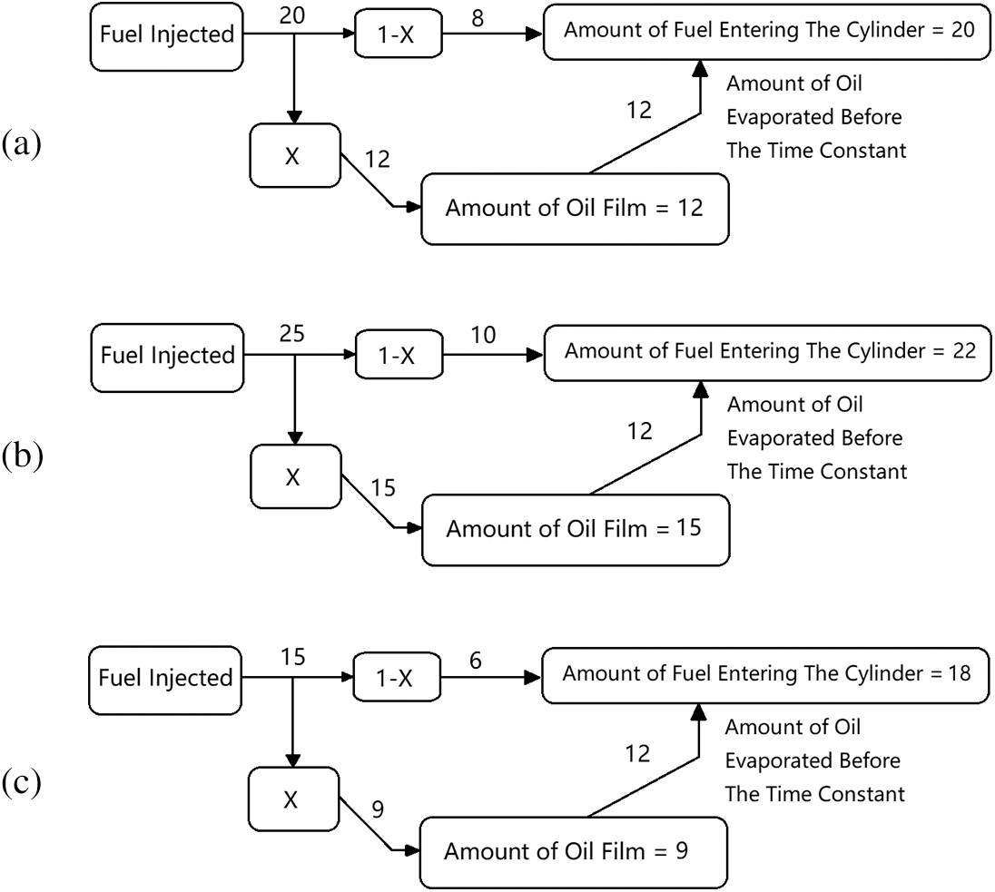
Figure 1: Schematic diagram of engine oil film dynamic effect. (a) Dynamic effects of oil film in steady state. (b) Dynamic effects of oil film during deceleration. (c) Dynamic effects of oil film during deceleration
In the steady state of the engine, the total amount of fuel injected by the injector is 20 units, and the amount of coanda oil film is 12 units. At this time, the oil film is in dynamic equilibrium, so the amount of oil film evaporated before the time constant is 12 units, the total amount of fuel entering the cylinder is 20 units, which is equal to the amount of fuel injected by the injector. At this time, the oil film has no effect on the working process of the engine. Under acceleration conditions, the throttle is developed, the intake air volume is increased, and the total amount of fuel injected by the injector is 25 units, of which 15 units are attached to the wall to form an oil film, and the amount of oil film evaporated before the time constant is still 12 units. Therefore, the amount of fuel entering the cylinder decreases and the mixture becomes lean. During deceleration conditions, the intake air volume is reduced, the fuel injector ejects 15 units of fuel, the amount of fuel entering the oil film is 9 units, and the amount of fuel evaporated is 12 units. The fuel entering the cylinder increases, resulting in the gas mixture becoming richer [6].
2.1.2 Establishment of Oil Film Model
According to the previous analysis, the amount of Coanda oil film will increase with the increase of the fuel injection quantity of the injector, and the temperature rise of the inlet wall and the fluid flow can promote the evaporation of the oil film. The study found that the amount of Coanda oil film is related to engine speed and load. However under large load, high speed and sufficient engine heat, the deviation of air-fuel ratio caused by oil film effect is not obvious. The fuel is injected at the junction of the intake valve back and the intake port. Some of the fuel falls on the intake valve back. Due to the high temperature of the valve back, this part of the fuel is quickly evaporated, and an oil film cannot be formed. Only the part of the fuel falling on the intake duct can adhere to the wall surface to form an oil film. In this paper, the influence of factors such as engine fuel injection, fuel drop point, cylinder inner wall temperature, and inlet fluid on the oil film is considered. The oil film quality prediction model is established as follows:
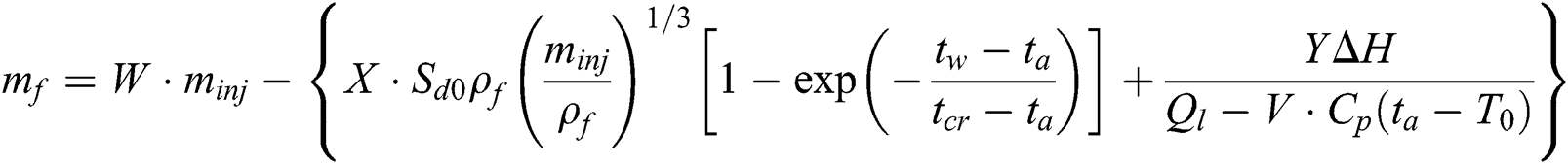
In this formula, mf is the mass of the oil film, minj is the fuel injection amount corresponding to the theoretical air-fuel ratio under steady-state conditions of the engine per cycle, Sd0 is the area occupied by the fuel injection on the back of the intake valve, ρf is the fuel density, tw is the temperature of the inner wall surface, tcr is the highest temperature at which the wall temperature has a significant effect on the evaporation of the oil film. Above this temperature, the evaporation of the oil film does not vary much with the increase of temperature, so it is not considered. ΔH is the change rate of the internal energy of the inlet fluid, which can be calculated by the GT-Power software. Q1 is the calorific value of gasoline. V, W, X, Y are dimensionless parameters.
The first term on the right side of the model equation,  characterizes the relationship between the oil film quality and the fuel injection amount per cycle of the engine. The ratio of the oil film to the injected fuel is W.
 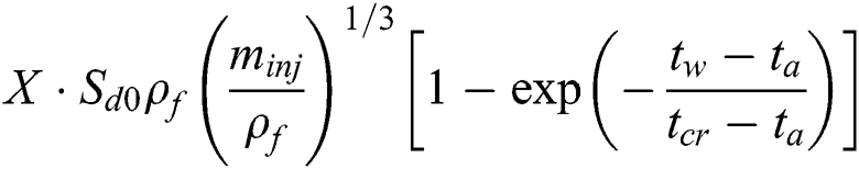 is the influence of the temperature of the valve back of the intake valve and the inner wall of the cylinder on the evaporation of the oil film.
 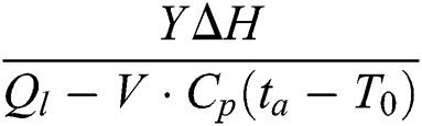 represents the effect of inlet fluid flow on the amount of oil film [7].
2.2 Experimental Measurement of Compensation Oil Quantity in Transient Conditions
The experiment needs to be performed when the engine is not heated, because the oil film on the inlet wall is thicker, and the air-fuel ratio deviation caused by the oil film effect is more obvious. In transient conditions, the dynamic balance of the oil film is broken due to rapid changes of the air volume in the intake port. When accelerating, the amount of injected fuel entering the oil film is greater than the amount of oil film evaporation. At this time, the oil film becomes thicker and the amount of fuel entering the cylinder decreases, resulting in leaner air-fuel ratio. The amount of oil that the engine needs to compensate is the amount of oil film increase, which is equal to the deviation of the amount of oil that causes a lean air-fuel ratio in the exhaust when there is no compensation control, which is hereinafter collectively referred to as “transition condition compensation oil amount”. The measurement of the compensation oil amount under the transition conditions under different transition conditions is helpful to analyze the trend of the oil film during the transition.
The greater the energy of the air flow passing through the surface of the oil film, the greater the ability to damage the oil film. The oil film becomes thinner because of the evaporation, and the amount of oil to be compensated will be reduced accordingly. In this experiment, we tested the following transient condition separately when the te, the temperature of the engine head, is 20°C, 30°C and 60°C: the rotation speed increases from 2000 to 7000 rpm, and the load increases from 4% to 70%. The experimental data was collected by the FAI-Motors software system, and its interface is shown in Fig. 2.
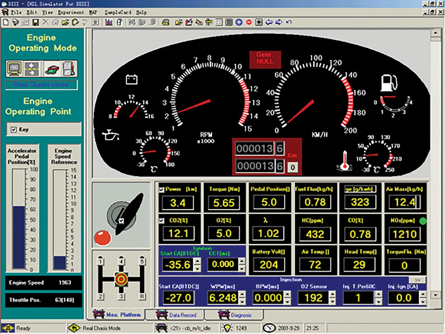
Figure 2: FAI-Motors development system interface
After selecting the test condition point, start the engine to make the engine quickly change to the target condition 2 after the target condition 1 runs stably. Let the actual air-fuel ratio per cycle during the transition be  , A is the air quality and F is the fuel quality. The air-fuel ratio is affected by three factors: (1) Lag of sensor response; (2) Filling effect of intake cavity, causing deviation of intake air flow at the throttle valve from intake air flow entering the cylinder; (3) Oil film effect. For the first factor, including the flow time of the gas, the lag time is generally close to a constant, between 0.06 and 0.2 seconds, which can be ignored. For the second factor, because the volume of the motorcycle’s air intake cavity is very small, it is also unnecessary to consider, so the gas volume in the transition condition can be approximately considered to be equal to the gas volume when the target condition 2 is stable, which is set as Q; The fuel quantity in the steady state has been calibrated to correspond to the fuel injection quantity with a theoretical air-fuel ratio of
  . The EFI control system does not have a transition condition compensation, so the change in fuel quantity per cycle in the transition condition is:
When the working condition 2 is stable, the corresponding amount of oil at the steady air-fuel ratio Q at the steady state is  . Therefore, we can get:

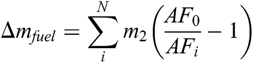
From the above two formulas, the change of oil quantity per cycle is:
Let the number of cycles in which the air-fuel ratio change from working condition 1 to working condition 2 be N, then the total amount of oil change during the transition is:
Before the test, it is necessary to calibrate the fuel quantity MAP at each operating point of the engine under steady-state conditions to ensure that the amount of fuel to be compensated in the transition conditions is obtained. The engine needs to stand still to the same temperature as the room temperature, and start running from the cold state. Use the chassis dynamometer to make the engine quickly stabilize at the target speed, and collect the engine cylinder head temperature. When the cylinder head temperature reaches the test temperature, the throttle opening is quickly changed to stabilize the throttle opening at the target value. The actual air-fuel ratio  and total cycle number N of each cycle of the transition process were recorded by the test data acquisition software, and the steady-state oil quantity of the target operating condition 2,
  was recorded. The above formula can be used to calculate the compensation oil amount for this transient condition [8].
2.3 Analysis of Model Simulation Results and Experimental Results
In the transient condition, when the throttle opening is stable and the speed is varied, the air-fuel ratio does not change significantly, because the variation in speed is a gradual process, and the oil film effect is not obvious. The experiment mainly calibrates and verifies the change of the oil amount compensation under variable load at a constant speed. The engine load can be adjusted by changing the engine throttle opening. The test was carried out by means of a chassis dynamometer. And because the engine is not easy to catch fire at a small throttle opening, the engine temperature rises rapidly under high load at high speed, and the oil film is completely consumed in a short period of time, which will cause certain effects and errors in the experiment. Therefore, the test and verification are mainly performed for medium load and medium speed.
As shown in Fig. 3, the engine collects data points every working cycle in the experiment. As can be seen from the figure, the compensation oil amount of the first few cycles of the engine’s transient operating conditions gradually increases, and it lasts for about 10 cycles to reach the maximum value of the compensation oil amount, and then the compensation oil amount gradually decreases every cycle. Its decay speed is far less than the increase speed, and the duration is longer. Therefore, the oil quantity compensation control model in the transition condition can be divided into short-term term and long-term term. The short-term action interval is only the cycle interval from the beginning of the transition to the maximum fuel compensation. Each cycle has a larger amount of compensated fuel, but the decay is fast and the duration is short; the long-term term affects the entire transition process, which has less oil compensation per cycle, but has a long duration. The total fuel compensation per cycle is equal to the sum of the short-term fuel compensation and the long-term fuel compensation. Fig. 4 shows the change trend of the compensation oil amount under transient conditions when the engine cylinder head temperature is 30°C under different load changes. When the engine speed is constant and the transition is between medium loads, the amount of oil that needs to be compensated is the most, and the transition between small loads and large loads requires less oil. Although the total compensation oil volume is less when the load changes from 4% to 10% compared to the load change from 10% to 30%, the gas volume of the two operating conditions does not vary much when the load changes, and the variation of air-fuel ratio is also obvious (Fig. 5). This shows that the oil film effect is still significant at this time [9].
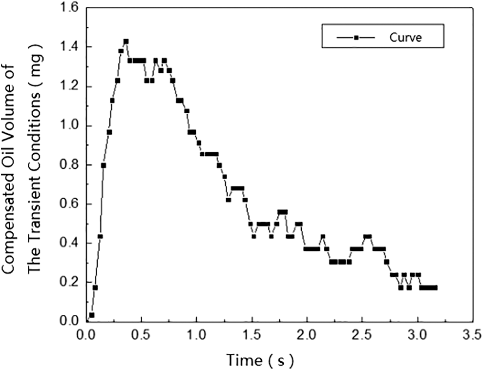
Figure 3: Fuel compensation per cycle at 3000 r/min, te = 30°C
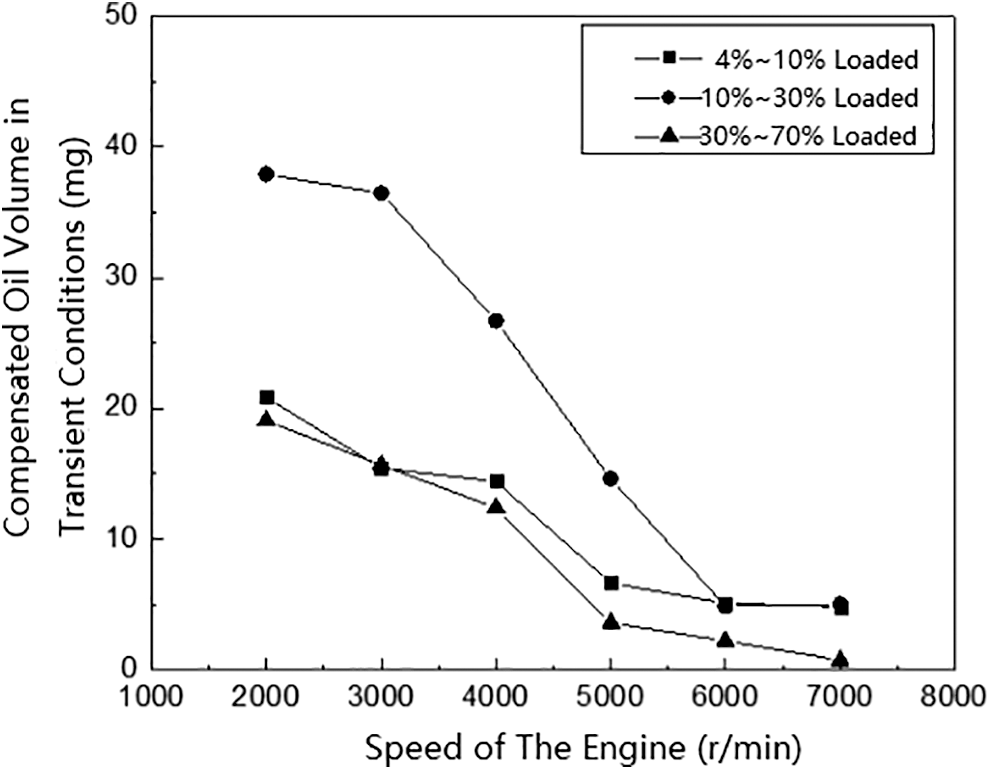
Figure 4: Effect of load change on the amount of compensation oil in transient conditions
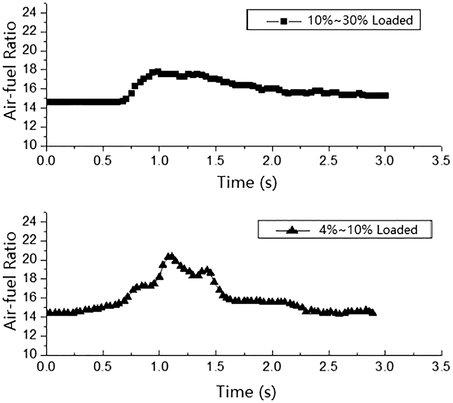
Figure 5: Air-fuel ratio at transient conditions of 3000 r/min under different load changes
In the transient operating conditions of the engine, the presence of oil film in the intake port will cause the engine fuel transmission to be delayed. The air velocity in the air inlet is one of the main factors affecting the oil film. When the air flow passes through the surface of the oil film, the aerodynamic force on the oil film can overcome the tension on the surface of the oil film, which increases the area of the oil film and increases the heat transfer coefficient, which is conducive to the evaporation of fuel from the oil film. As shown in the previous numerical simulation results, the engine speed is constant, the larger the load, the greater the airflow speed, which is conducive to the evaporation of the oil film. Therefore, only a small amount of oil needs to be compensated in the transient conditions under large loads.
Another main factor affecting the oil film is the wall temperature of the air inlet. The increase of the wall temperature of the air inlet will promote the endothermic evaporation of the oil film. The higher the engine temperature is, the greater the amount of evaporation and the thinner the oil film will become, so the oil film effect in the transition conditions turns less. When the throttle change slope, change speed and engine head temperature are constant in the transition conditions, the oil amount compensated for the transition conditions decreases with the increase of the rotation speed at different speeds. When the rotation speed increases above 7000 r/min, the amount of oil that needs to be compensated for changing the throttle opening is pretty small. This is because as the rotational speed increases, the temperature of the inlet wall surface increases, and the oil film effect caused by the thinning oil film is weakened. When the engine temperature is hot enough, the amount of oil film is greatly reduced. At this time, as the increase of the intake air temperature promotes the vaporization of the fuel, the injected fuel can be basically vaporized into the cylinder, and the amount of fuel to be compensated is very small. Fig. 6 shows the measured results of the compensated oil quantity when the speed is constant and the throttle opening is increased from 10% to 30%. In the figure, te is the temperature of the engine cylinder head. Experiments have shown that when the temperature of the engine cylinder head is low, the amount of oil compensated is more, and when the temperature of the engine cylinder head is increased, the amount of oil compensated is reduced [10,11].
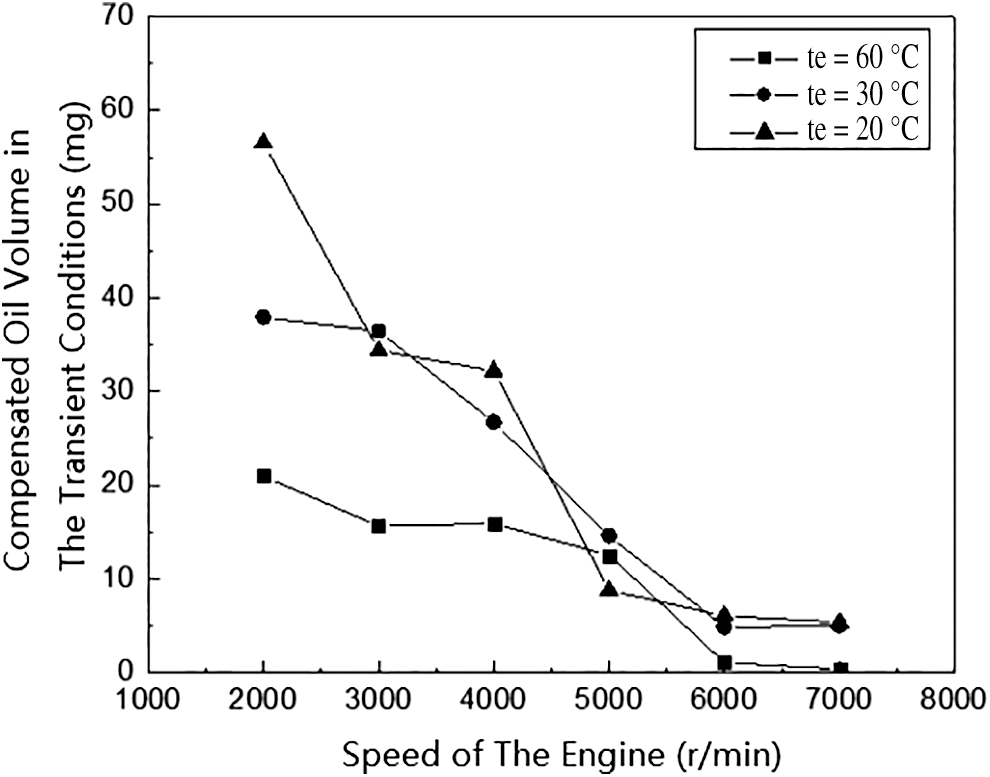
Figure 6: Compensating oil quantity in transient conditions at different engine head temperatures
In addition, the change of the pressure (vacuum degree) in the inlet will also cause the change of the boiling state of the evaporated gas in the oil film, which will cause the transient fuel evaporation rate to change. When the pressure in the intake port is constant, the oil film in the intake port is in a relatively balanced state, and the rapid change of the throttle valve breaks the balance in the intake port, causing the intake port pressure to decrease. The saturated partial pressure of fuel vapor may cause the fuel in the oil film to boil and increase the amount of evaporation. From the previous analysis, it can be known that the higher the speed, the lower the pressure in the intake port, and accordingly, the lower the oil film amount at high speed [12].
Based on the above-mentioned experimental and theoretical studies, an oil film distribution model per cycle for the transition condition was established based on the engine inlet oil film model. The oil film model describes the total amount of oil film changes in the engine’s transient operating conditions, while the oil film distribution model can describe the amount of fuel that needs to be compensated due to the oil film effect in each cycle of the engine’s operating conditions. Fig. 7 shows the experimental measurement curve and model prediction curve for the fuel compensation per cycle in the transition condition from 10% load to 30% load. The model established can be in good agreement with the experimental results and meet the fuel compensation trend in the transition condition. In fact, the short-term term of the oil film effect caused by changes in the throttle opening is extremely short, lasting only a few cycles, while the short-term term actually measured lasts about 10 cycles. This is because in addition to the oil film effect which causes the air-fuel ratio deviation in the transient operating conditions described above, there are also factors of the sensor response lag and the intake cavity filling.
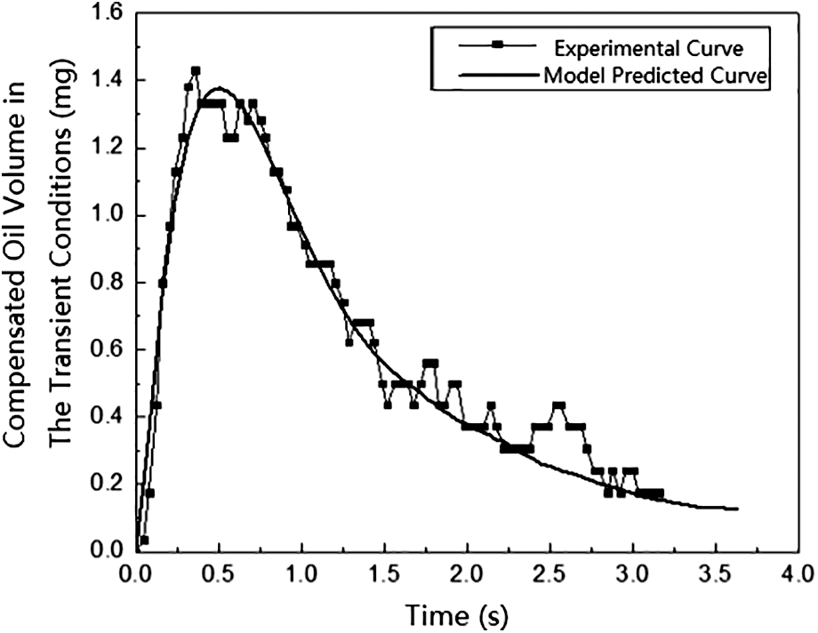
Figure 7: Predicted and experimental curves of fuel compensation per cycle in the transient condition at 3000 r/min, te = 30°C
Based on the measurement of the compensation oil quantity in the transition conditions under different transition conditions, the variation of the oil film during the transition is analyzed. The experimental results show that the velocity of the airflow in the intake port and the temperature and pressure on the wall of the intake port are the main factors affecting the oil film in the cylinder. According to the experimental and theoretical studies, the oil film distribution model for each cycle of the transition condition was established, and the model is in good agreement with the experimental results. The oil compensation for the transient conditions is realized, which is definitely helpful to achieve accurate control of the air-oil ratio.
Funding Statement: This research was funded by Longquan Innovation Center of Zhejiang University.
Conflicts of Interest: The authors declare that they have no conflicts of interest to report regarding the present study.
References
1. Ding, C. P., Vuilleumier, D., Kim, N. (2020). Effect of engine conditions and injection timing on piston-top fuel films for stratified direct-injection spark-ignition operation using E30. International Journal of Engine Research, 21(2), 302–318.
2. Han, X. G., Chen, W. B., Yuan, X. S., Guan, J., Chen, Z. Z. et al. (2018). On-line measurement technology of oil film distribution status of horizontal cylinder liner engine. Internal Combustion Engine Engineering, 39(4), 23–28.
3. Bielaczyc, P., Merkisz, J. (1999). Euro III/Euro IV emissions—A study of coldstart and warm up phases with a SI (spark ignition) engine. SAE Paper 1999-01-1073.
4. Zhang, Y. Z. (2017). Study on movement and evaporation characteristics of fuel spray against wall and oil film. Dalian: Dalian University of Technology.
5. Huang, K. S. (2019). Transient fuel film compensation of a MPI gasoline engine based on the MVEM. Proceedings of the 2019 China Automotive Engineering Society Annual Meeting. China: Society of Automotive Engineers, China Automotive Engineering Society, 120–130.
6. Schulz, F., Beyrau, F. (2019). The effect of operating parameters on the formation of fuel wall films as a basis for the reduction of engine particulate emissions. Fuel, 238, 375–384.
7. Lubricants. (2018). Findings from Tianjin University yields new data on lubricants (experimental investigation on effect of wall roughness and lubricant film on the adhered fuel film of N-Butanol-Diesel blends after spray impingement). Energy Weekly News, 15, 22–23.
8. Hänichen, P., Eyk, M. V., Stephan, P. (2018). Experimental investigations of fuel film evaporation with deposit formation. International Journal of Heat and Fluid Flow, 70, 104–113.
9. Geiler, J. N., Grzeszik, R., Quaing, S. (2017). Development of laser-induced fluorescence to quantify in-cylinder fuel wall films. International Journal of Engine Research, 19(1), 134–147.
10. Ming, G. (2018). Study on the characteristics of the oil film and the near-wall flow field in the wall of the diesel spray against the wall. Tianjin: Tianjin University.
11. Schulz, F., Beyrau, F. (2017). The influence of flash-boiling on spray-targeting and fuel film formation. Fuel, 208, 587–594.
12. Ge, J., Li, Y. L., Liu, D. Y., Liu, B. F. (2016). Identification of oil film parameters in gasoline engines under transient conditions. Henan Science and Technology, 21, 129–132.
 | This work is licensed under a Creative Commons Attribution 4.0 International License, which permits unrestricted use, distribution, and reproduction in any medium, provided the original work is properly cited. |