DOI:10.32604/EE.2020.013572
| Energy Engineering DOI:10.32604/EE.2020.013572 | |
| Article |
Experimental Thermal Performance of Different Capillary Structures for Heat Pipes
1Federal University of Technology—Parana (UTFPR), Ponta Grossa, 84.017-220, Brazil
2Federal University of Technology—Parana (UTFPR), Curitiba, 81.280-340, Brazil
*Corresponding Author: T. Antonini Alves. Email: antonini@utfpr.edu.br
Received: 11 August 2020; Accepted: 08 September 2020
Abstract: The temperature control in electronic packaging is the key in numerous applications, to avoid overheating and hardware failure. Due to high capability of heat transfer, good temperature uniformity, and no power consumption, heat pipes can be widely used for heat dissipation of electronic components. This paper reports an experimental thermal analysis of different capillary structures for heat pipes. The wicks considered are metal screens, axial microgrooves, and sintered metal powder. The heat pipes are made of copper, a 200 mm length tube and a 9.45 mm external diameter. Working fluid used was distilled water. The devices are investigated in three positions: 0, 90, and 270° to the horizontal under powers of 5 up to 45 W. The results show that in horizontal (0°) and with the evaporator under the condenser (270°), the heat pipes showed similar results. Nevertheless, in the reverse condition (the position against the gravity with the evaporator above the condenser, 90°), the heat pipe with sintered wick presented the best thermal performance, as it has the lowest thermal resistance and supported a higher power. Besides that, the sintered powder capillary structure demonstrates the most homogeneous thermal behavior for every position, making the most suitable for applications susceptible to diverse inclinations.
Keywords: Heat pipes; capillary structure; thermal performance; sintered wick
The modernization of electronic technology leads to miniaturization and high power density in electronic devices [1]. Limiting the maximum operating temperature results in an increase in packaging complexity making the conventional cooling modes inadequate to guarantee the performance, price, and safety of electronic devices [2]. Thus, the temperature control in electronic packaging is the key in numerous applications, to avoid overheating and hardware failure [3].
Aiming to achieve an efficient heat dissipation of great heat fluxes, many advanced cooling technologies have been introduced in the thermal controlling, including boiling cooling, liquid cooling, functional surface, microchannels heat sink, heat pipes, microfluidic engineering, and metal foam [4]. Due to high capability of heat transfer, good temperature uniformity, and no power consumption, heat pipes are widely used for heat dissipation of microelectronic units under high power density [5].
Heat pipes are as biphasic heat exchangers that can stabilize the microelectronic device’s temperature as a good technological alternative. They are one kind of passive devices able to dissipate a substantial amount of heat by a relatively small temperature drop and a working fluid flow inside the capillary structure [6]. Their efficiency and convenience gave a prominent place to these devices in recent researches. Authors study their application in areas as telecommunications and electronics, including the aerospace applications [7]. The main benefits of this technology include low global thermal resistance, no energy consumption, fixed components, and low-pressure loss [8].
According to [9], the heat pipe operation is as follows: Heat is transported from the heat source to evaporator, which vaporizes the working fluid. The difference in pressure associated with density variation carries vapor to condenser. Thus, the transported heat is discarded to the heat sink, which condenses the vapor. The liquid returns back to evaporator by the capillary action of the wick. The adiabatic section does not exchange heat with the surroundings. Fig. 1 presents a sketch of the main regions of the heat pipe and its operation. Additional information of heat pipes, their operation and application can be obtained in [10–13].
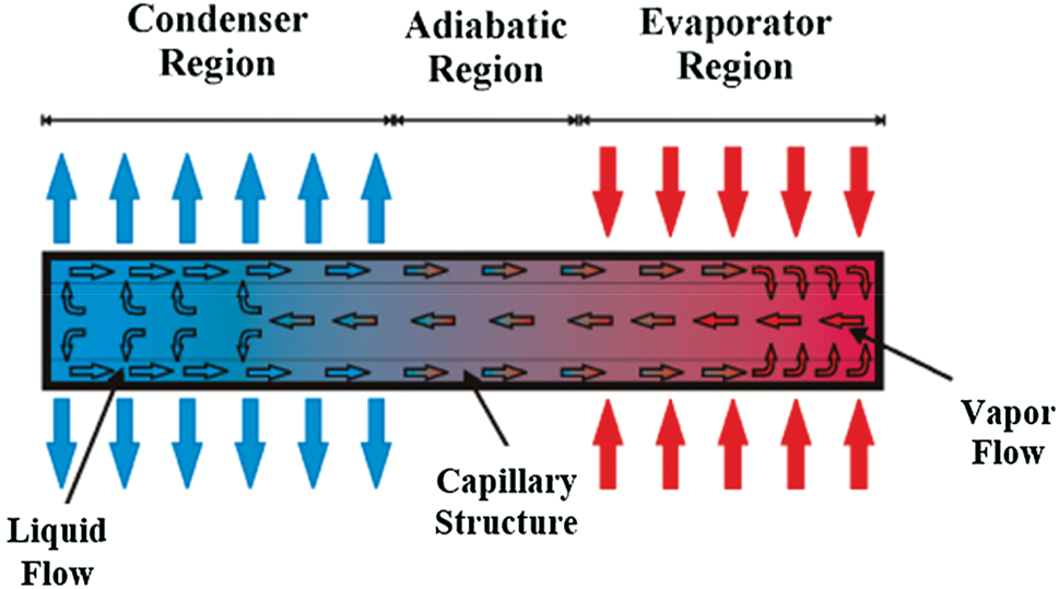
Figure 1: Main components and operation of heat pipes
A heat pipe is made up of a sealed container with some capillary structure placed on the inner surface of the pipe. The wick provides a capillary-driven pumping effect for returning the condensate to the hot side of the tube. Enough working fluid is placed inside the sealed pipe to saturate the wick with liquid [14]. The main capillary structures are screen meshes, sintered metal powder, and grooves [15]. Because of facility of manufacture, big capillary pumping, and convenience the screen meshes are the most common wick [16]. The principal features of micro-grooved capillary structures are elevated thermal conductivity and permeability [17]. The sintered wicks have big capillary pumping capacity, resulting of the sintering method that solidifies metal particles on the internal surface of the tube [18]. Available technologies of capillary structure for the application in the management of temperature in electronic packaging are presented in [19–36].
The literature survey shows that available information and data on the comparative thermal behavior of different wick structures for heat pipe are scarce. Considering that, in the present study, the thermal performance considering different capillary structures in three positions: 0, 90, and 270° to the horizontal is investigated. The considered structures are screen mesh, axial microgrooves, and sintered metal powder.
The fabrication methodology, which includes the cleaning and assembly of the parts, the tightness test, the vacuum realization, and the charging with working fluid, experimental tests and data treatment follow the procedures described by [37].
2.1 Characteristics of the Developed Heat Pipes
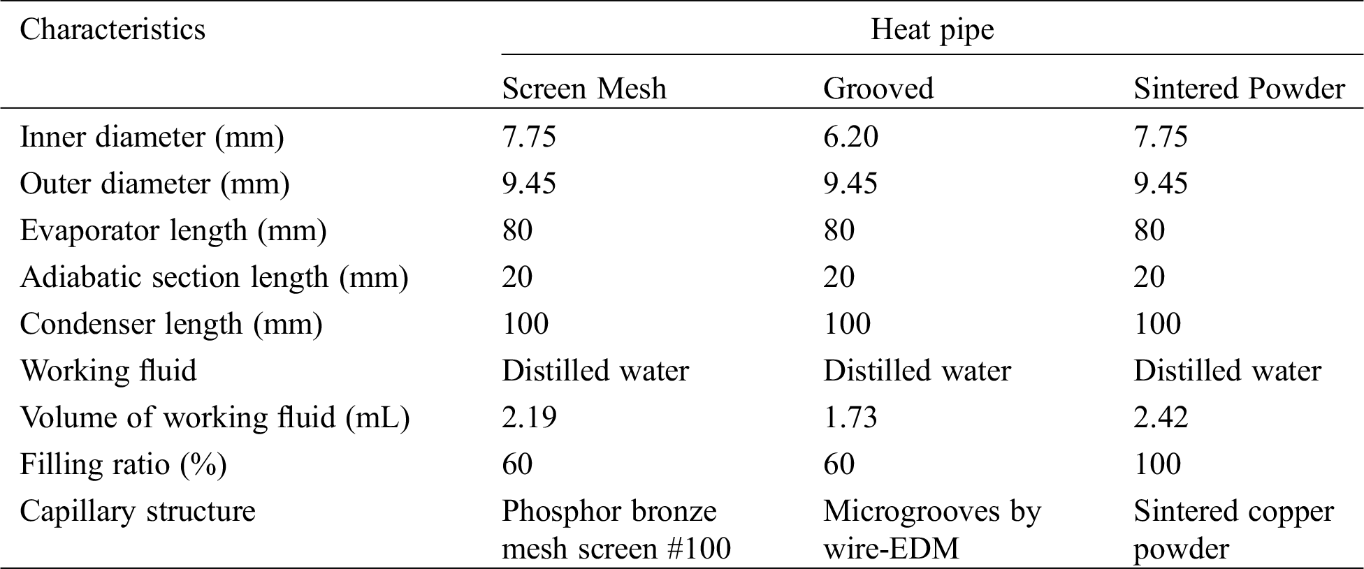
Copper tubes ASTM B-75 Alloy 122 with 9.45 mm external diameter, 7.75 mm internal with 200 mm length were used to manufacture the heat pipes. All of them have 80 mm of evaporator, 20 mm of adiabatic region, and 100 mm of condenser. Distilled water was applied as working fluid, with filling ratios based in the volume of evaporator. Preliminary experimental tests were performed to find the filling ratio with the best thermal performance of each wick, since the porosity, permeability, and pore radius vary according to the capillary structure. Tab. 1 summarizes each developed heat pipe.
Table 1: Summary of the main physical characteristics of heat pipes
One of the most important criteria for choosing each capillary structure is the heat transfer capability of them. It is noteworthy that the capillary properties and the heat transfer capabilities of heat pipes depend not only on the type of capillary structure but also on their characteristics. For a screen mesh, the number of layers and cell size must be accounted for; for microgrooves the profile, depth and pitch of grooves are essential elements; while for sintered metal powder the particle size, layer thickness, and porosity are influencing factors. In this context, for the comparison of different capillary structures in this work, previous experimental studies provided the best parameters for the better thermal performance of each wick. The researches were [38–40] for screen mesh, microgrooves, and sintered powder, respectively.
A single layer of phosphor bronze mesh #100, Fig. 2a, makes the wick of heat pipe with screen mesh. A wick micrograph, obtained by a Backscattered Electron Detector for SEM, is presented in Fig. 2b. Further aspects of the heat pipe with screen mesh can be acquired in [38].
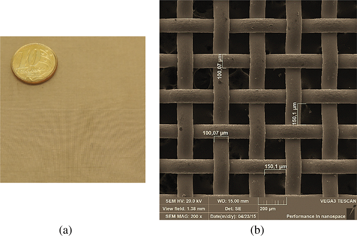
Figure 2: Screen mesh capillary structure. (a) general view, (b) micrograph
Wire electrical discharge machining, also known as wire-EDM, by a Fanuc™ machine tool (model Robocut α-oic) with command Fanuc™ (Series 180is-WB) fabricated 32 axial microogrooves in a copper tube, which formed the capillary structure of the grooved heat pipe [39]. A brass wire electrode (DIN 160) with a 0.2 mm diameter and 900 N/mm2 tensile was used. The parameter settings were an open circuit voltage at 41 V, a constant discharge current of 4 A, and a wire run-off speed of 0.40 mm/min, achieving accuracy of ± 6 µm. Deionized water dielectric fluid was responsible for concentrating the energy and cooling the wire and work-piece. The wick design is demonstrated in Fig. 3a. The details of microgrooves are shown in the micrograph, Fig. 3b. The mean diameter of microgrooves is 220 μm.
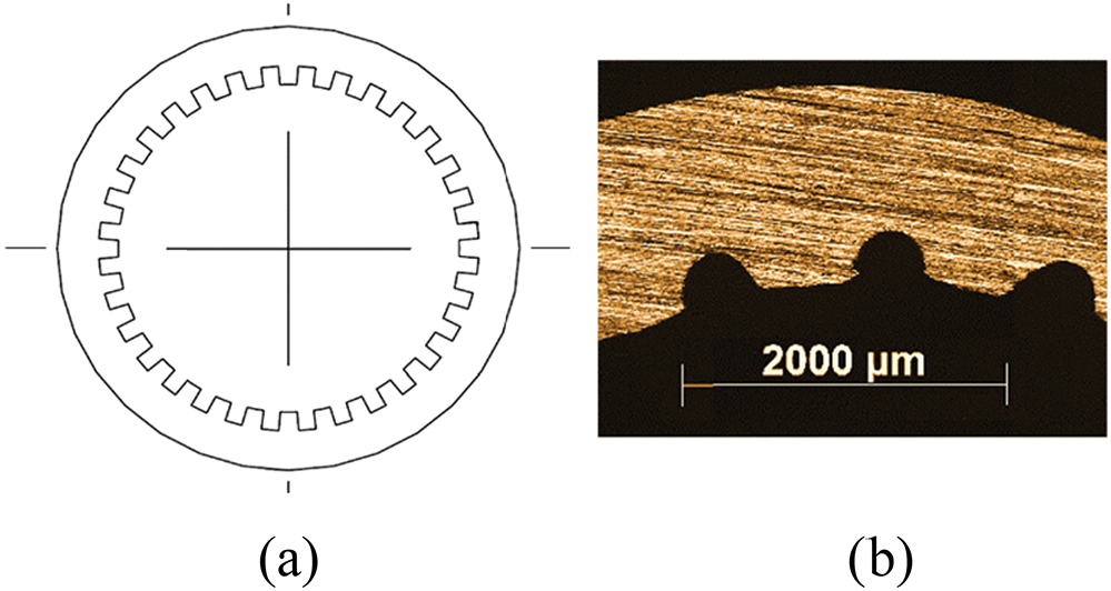
Figure 3: Axial microgrooves capillary structure. (a) schematically view, (b) micrograph
A monomodal copper powder and a temporary mandrel were used in a sintering process, which produced the sintered heat pipe—Fig. 4a. The volume-based average particle diameter of the powder is 33 μm and the wick thickness is 1.5 mm. The apparatus used in the sintering process consisted of a controlled atmosphere horizontal tubular furnace (Inti™ FT-1200), a data acquisition system (Agilent™ 34970A with 20 channels), and a laptop (Dell™). The gas used in the atmosphere control was a mixture of 95% of Argon and 5% of Hydrogen. The sintering occurred at a heating rate of 20°C/min, with a 15-minute permanency at a temperature of 800°C, and subsequent cooling by air forced convection. The wick porosity was obtained by Helium Pycnometry associated with physical characterization by the Archimedes method, showing that the total porosity of the capillary structure is 54.8%. Fig. 4b presents a micrograph of the sintered powder capillary structure obtained by Backscattered Electron Detector (BSD) for SEM. Additional characteristics of sintered heat pipes are in [40].
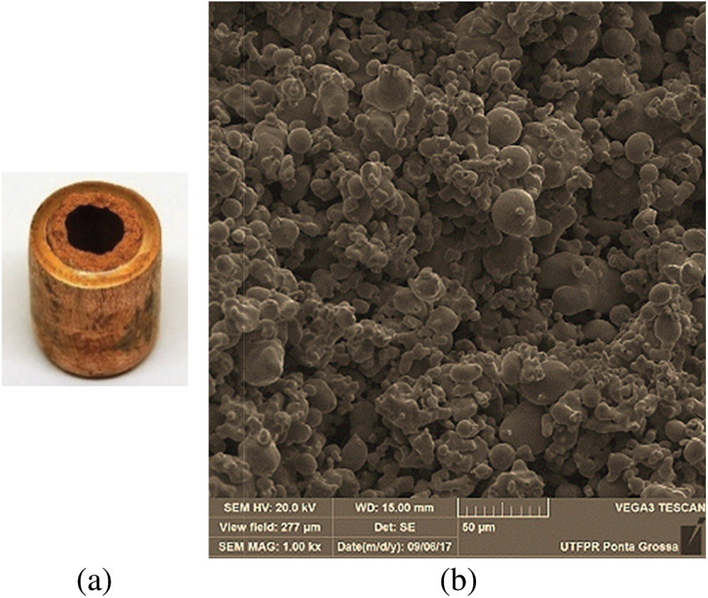
Figure 4: Sintered powder capillary structure. (a) general view, (b) micrograph
The experimental setup and experimental methods are adopted to estimate the thermal performance, ensuring similar conditions to that of the actual operation of a thermal management system.
Fig. 5 presents the apparatus applied in the experimental investigations. A power supply unit (Agilent™ U8002A), a data logger (Agilent™ 34970A), a laptop (Dell™), an uninterruptible power supply (NHS™), a universal support, and a fan (Ultrar™) constituted the experimental apparatus.
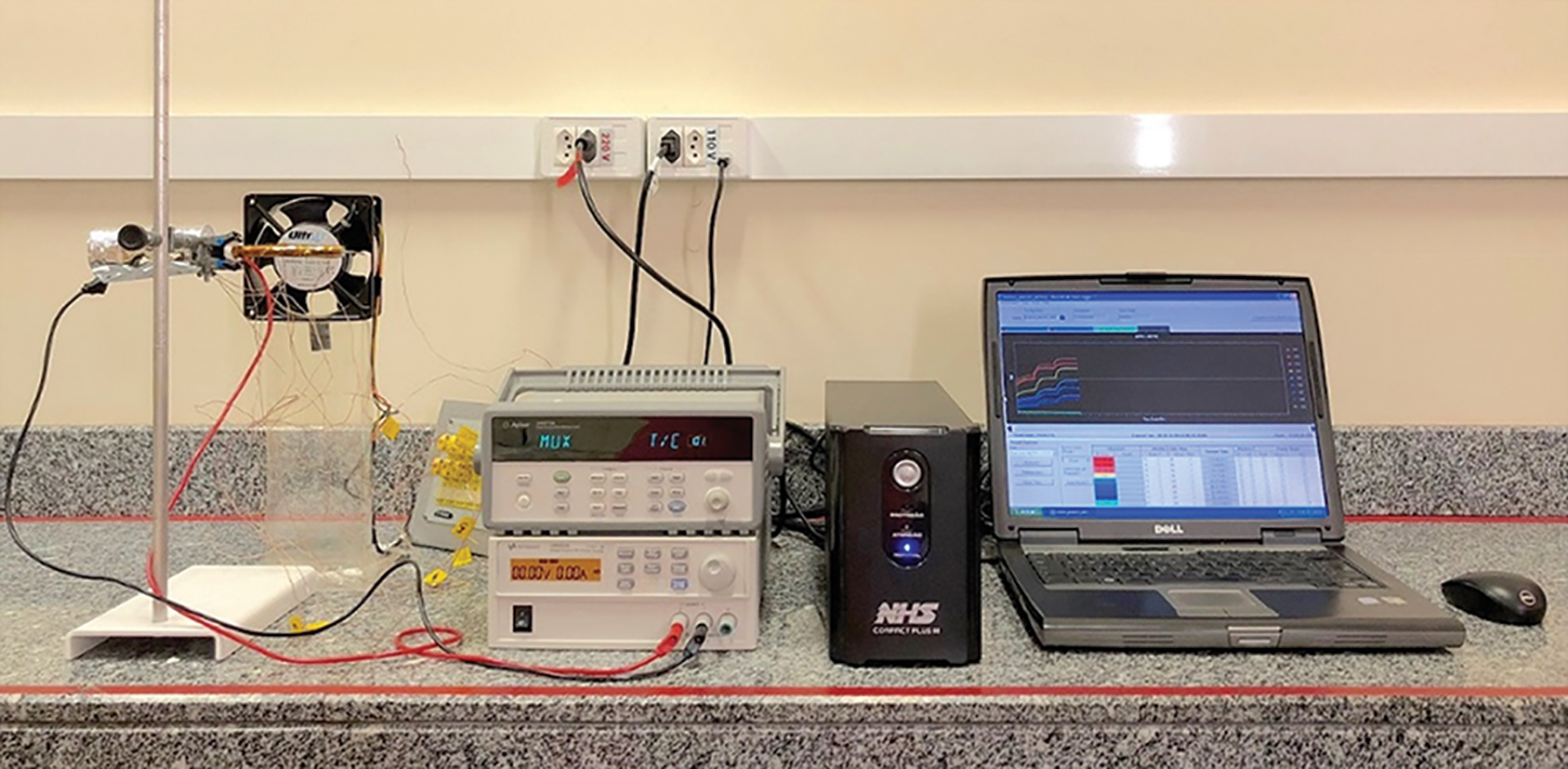
Figure 5: Experimental setup
The temperature monitoring was realized by K-type thermocouples Omega Engineering™, adhered to the external surface of devices by a thermosensitive adhesive strip Kapton™. Fig. 6 represents the thermocouple locations, being three in the evaporator (Tevap,1, Tevap,2, and Tevap,3), one in the adiabatic section (Tadiab), and four in the condenser (Tcond,1, Tcond,2, Tcond,3, and Tcond,4).
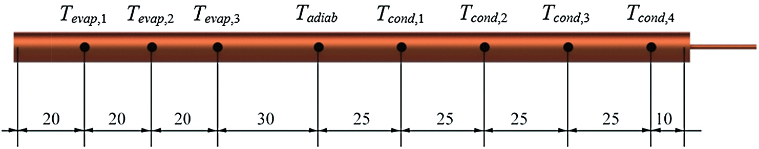
Figure 6: Thermocouple locations (mm)
Heat is generated by the Joule effect created by power dissipation in a strip resistor (nickel-chromium alloy Omega Engineering™) with 0.1 mm of thickness and 3.5 mm of width. An aeronautical thermal insulation MTI Polyfab™ and a coating of polyethylene 3M™ protect the evaporator from losing heat to the surroundings. Tape of fiberglass Omega Engineering™ is used for the thermal insulation at the adiabatic region. The condenser uses air convection as the heat sink.
An air-conditioning system Carrier™ maintains the room temperature at 19°C ± 1°C and, in this way, guaranteeing the experimental repeatability. The tests were done in three different operation positions: 0°, 90° (evaporator above condenser), and 270° (evaporator under condenser) referred to the horizontal. They were carefully fixed at the test positions by the adiabatic section with universal support in Fig. 7. Every test has a checklist to be done, which guarantees that the thermocouples, insulation, and resistor connection are rightly installed. The fan at 5.0 m/s is positioned on the cold side and the combined error is ± 0.2 m/s. Mean air velocity was calculated in accordance with the American Society of Heating, Refrigerating and Air-Conditioning Engineers (ASHRAE) Handbook [41]. The system that acquired data is switched on and verified if all the temperatures are almost the same as the room temperature. If yes, the desired power is dissipated to the resistor.
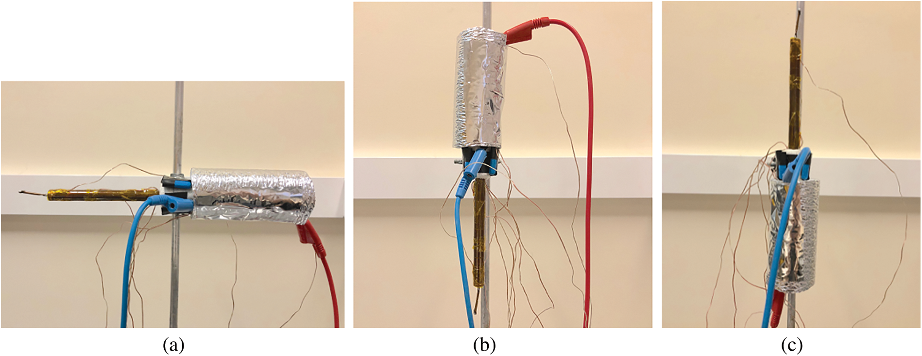
Figure 7: Inclinations of tests. (a) horizontal, (b) 90° to the horizontal (evaporator above condenser), (c) 270° to the horizontal (evaporator under condenser)
The thermal load starts with 5 W, which stays approximately 15 minutes when the thermocouples present stationary values. So, the power receives an increment of 5 W. Critical temperature determines the maximum power that can be dissipated through heat pipe. For this study, the highest temperature is 150°C, which can promote the materials melting. The thermocouple data is obtained every five seconds and recorded by software Agilent™ Benchlink Data Logger 3.
The uncertainties are related to thermocouples, data logger, and heat load supply unit. An error propagation model described by [42] was adopted to determine the electrical power uncertainty, obtained from the electrical resistors, and to determine uncertainties of thermal resistance. The thermocouple uncertainties were estimated in the accuracy of ± 2.2°C, and the voltage and current were 0.35% + 20 mV and 0.35% + 20 mA, respectively. The uncertainties are rectangle type for all measures because the maximum and minimum values of variation of each equipment used are known. The determination of the combined uncertainty was described as the correlated type, owing to the nature of the data acquired through the experiment. It is estimated that temperature and thermal load uncertainties can be about ±1.27°C and ±1%, respectively.
Fluid dynamics laws for heat pipes manage the influences of gravity, as also the fluid flow in capillary structures. The heat transfer governs the boiling of working fluid that is facilitated by additional nucleation sites, usual in wicks. Therefore, the total thermal resistance represents the interaction of theses two areas inside heat pipes.
The total thermal resistance, Rth, of a heat pipe can be defined as the ratio of the total temperature drop across the device by the rate of total heat transfer [43]. The higher the thermal resistance, the greater the difficulty in transporting heat from the system [44]. The total thermal resistance can be calculated by

where, Tevap is the average wall temperature in evaporator, Tcond is the average wall temperature in condenser, and qin is the input heat on the evaporator.
The results of the thermal behavior of tested heat pipes are presented and discussed. The tests were of three different capillary structures (screen mesh, axial microgrooves, and sintered powder), operating in three positions (0, 90, and 270°). The thermal efficiency values are guaranteed by the repetition three times for each case, with the variance between the average temperatures of each region lower than 0.5°C. The dissipated thermal loads were from 5 up to 45 W.
The temperature distributions in horizontal contemplating the heat pipes: (a) with screen mesh, (b) grooved, and (c) sintered, are shown in Fig. 8. In this position, axial microgrooves and sintered powder wicks dissipated the maximum power of 40 W while the mesh heat pipe dissipated a maximum 45 W. The evaporator drying in grooved heat pipe initiates at 15 W, distancing the temperatures of the regions. So, at 40 W, there is a lack of working fluid, reaching the established critical temperature. The sintered wick has a late startup compared to the other two devices, 10 W, when the adiabatic and condenser temperatures increase rapidly. The vapor front moves towards the condenser as the power dissipation is increased. It begins to dry out at 25 W, when the evaporator temperatures start to hold off from the adiabatic section temperatures. Still, the sintered heat pipe works in safety until 40 W with condenser temperatures close to each other. However, the mesh heat pipe presented the most isothermal condenser and even if the evaporator initiates to dry out from 15 W, it can operate satisfactorily until 45 W.
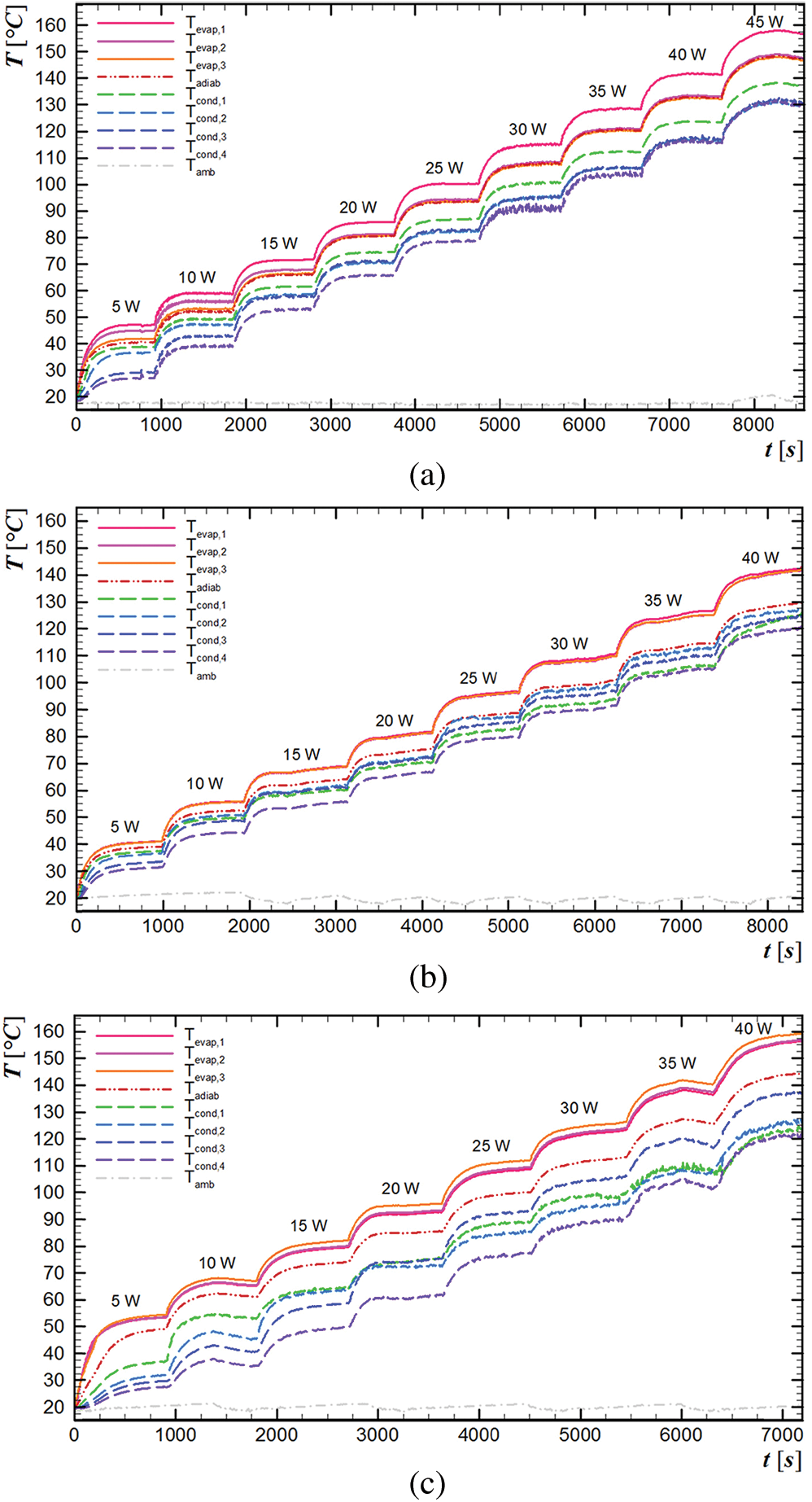
Figure 8: Temperature distributions vs time at horizontal. (a) mesh #100, (b) grooved, (c) sintered powder
4.2 Evaporator above Condenser
The temperature transition on time with the evaporator above the condenser (90° related to the horizontal) for devices with different capillary structures are presented in Fig. 9. For capillary structures of screen and microgrooves, the highest dissipated power was 15 W, while the sintered heat pipe dissipated a maximum of 35 W. The three wicks are known by their high capillarity, the screen mesh and the microgrooves cannot maintain wet the evaporator in conditions against gravity. This results in a sharply rise of evaporator temperature with heat load increment, showing that capillary force was not enough to overcome the gravity and allow the liquid to return efficiently to the hot side. Differently, the sintered heat pipe showed a similar performance of horizontal, working successfully until 35 W. The reducing from 40 to 35 W, when compared to horizontal, is due to the addition of the gravity force.
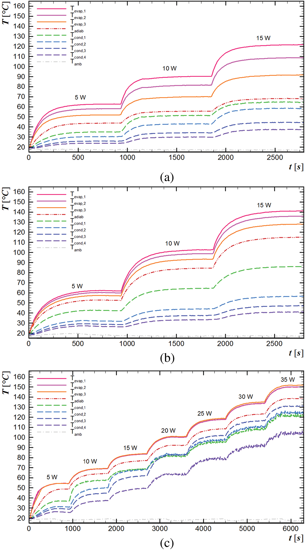
Figure 9: Temperature distributions vs time, 90° related to the horizontal. (a) mesh #100, (b) grooved, (c) sintered powder
4.3 Evaporator under Condenser
Fig. 10 demonstrates the temperature variation with time for the evaporator under the condenser for three types of capillary structures. In heat pipes with screen mesh #100 and with grooves, the maximum dissipated power was 45 W. The sintered heat pipe dissipated a maximum 35 W. In this position, all the devices operated aided with gravity, so similar performance is expected. With water inside the sintered powder this wick creates mini channels for the liquid movement, creating higher surface tension which restricts the fluid movement and reduces 5 W in maximum heat load.
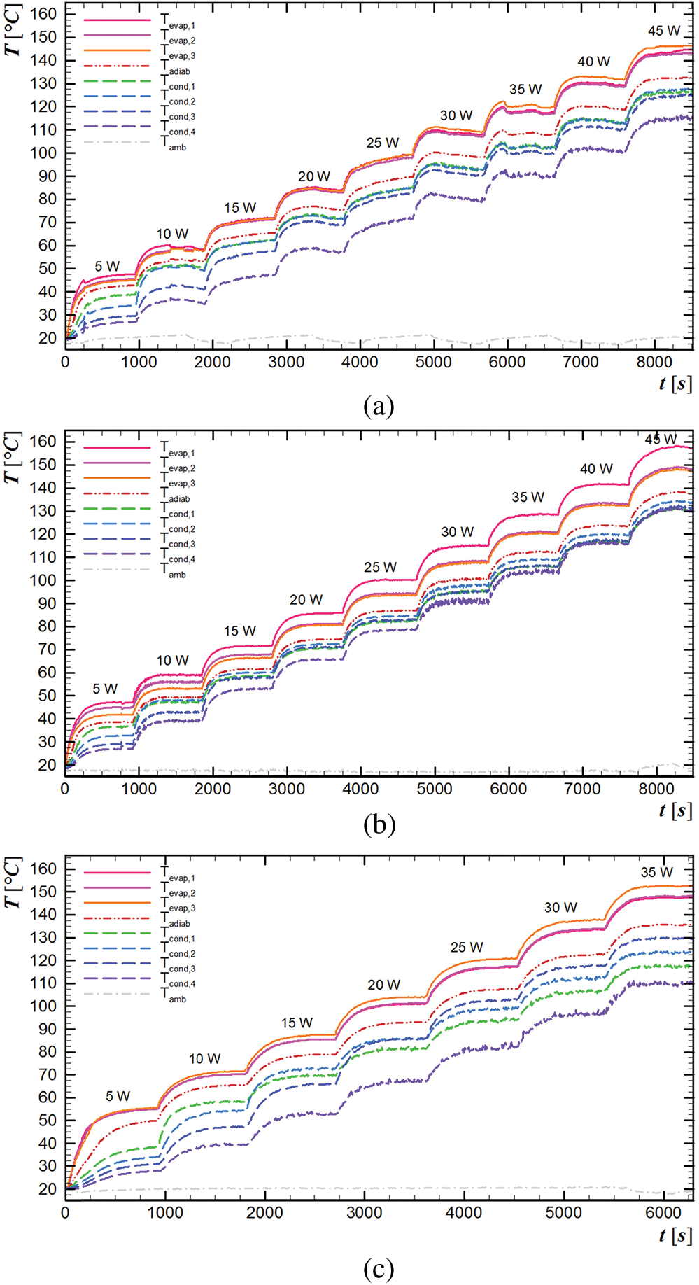
Figure 10: Temperature distributions vs time, 270° related to the horizontal. (a) mesh #100, (b) grooved, (c) sintered powder
Fig. 11 illustrates the comportment of the total thermal resistance for each dissipated power for the three capillary structures in different inclinations. The heat pipes’ thermal resistance decrease as thermal load is increased in the horizontal and evaporator under the condenser positions. This behavior is noticed since the application of the second heat load, when the vapor starts to move in addition to the conduction heat transfer mechanism. The wicks promote nucleation sites that boil the liquid early, starting the operation in lower heat loads. So, all the heat pipes work satisfactorily with a low thermal resistance and, as expected, in a similar way. The microgrooves showed the best thermal performance considering these two positions, which means providing the lowest thermal resistance. However, in adverse conditions, that is, in the position with the evaporator above the condenser, just the sintered heat pipe presented an adequate thermal performance, similar to the other positions. In this position, the grooved heat pipe works only with heat conduction, as the heat transfer mechanism, for all heat loads. The gravity force is too high for the capillary of the wick structure to heat, inhibiting the completion of the thermodynamic cycle inside the tube. The meshed heat pipe presents a little drop of thermal resistance in the beginning, but the low supply of working fluid in the evaporator makes the heat pipe support a low maximum heat load. In 90° to the horizontal, the sintered heat pipe presented the best thermal performance, since it has the lowest thermal resistance associated to a higher power.
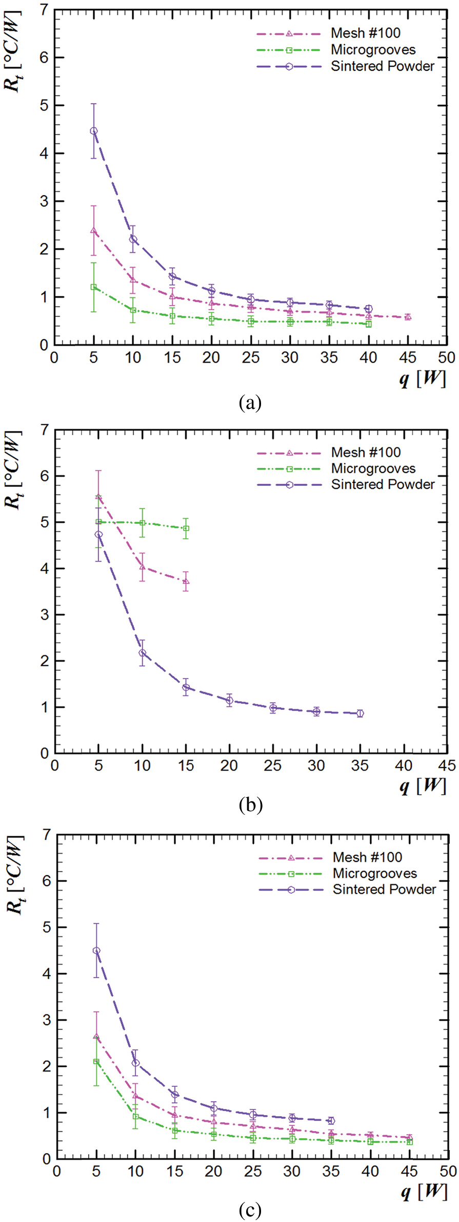
Figure 11: Total thermal resistance vs heat load. (a) horizontal, (b) 90° to the horizontal (evaporator above condenser), (c) 270° to the horizontal (evaporator under condenser)
Overall, evaluated heat pipes presented successful thermal behaviors, especially for the horizontal position and in a position where the evaporator is under the condenser, especially when there is some inclination with a slight gravity effect. The manufacturing methods of the wicks were appropriate. Therefore, the studied capillary structures are suitable for the application in temperature controlling of electronic components and devices. Nevertheless, the sintered powder heat pipe presented the most homogeneous thermal performance for every position, which makes it the most suitable candidate for applications susceptible to diverse inclinations.
This paper reported the results of an experimental thermal study of three capillary structures (a metal screen, axial microgrooves, and sintered copper powder) for heat pipes. Due to their geometry, they can be applied in the thermal controlling of electronic components and devices. The analyzed heat pipes showed that all capillary structures worked satisfactorily and with similar behaviors, especially for horizontal and with the evaporator under the condenser positions. The current manufacturing methods are adequate for this use. However, in an adverse position, against gravity, the sintered heat pipe showed the best performance. Besides that, the sintered powder capillary structure demonstrates the most homogeneous thermal performance for every position, making the most suitable for applications susceptible to diverse inclinations.
Acknowledgement: The authors acknowledge the Capes and the CNPq. Also, they concede acknowledgments to PROPPG/UTFPR, DIRPPG/UTFPR, PPGEM/UTFPR (Campus Ponta Grossa), and DAMEC/UTFPR (Campus Ponta Grossa).
Funding Statement: The authors received no specific funding for this study.
Conflicts of Interest: The authors declare that they have no conflicts of interest to report regarding the present study.
References
1. Alves, T. A., Altemani, C. A. C. (2010). Thermal design of a protruding heater in laminar channel flow Proceedings of the 14th International Heat Transfer Conference, 691–700. DOI 10.1115/IHTC14-22906.
2. Nishida, F. B., Alves, T. A. (2014). Conjugate cooling of 3D protruding heaters with laminar flow in a rectangular channel. International Review of Mechanical Engineering, 8, 360–369. DOI 10.15866/ireme.v8i2.462.
3. Alves, T. A., Altemani, C. A. C. (2008). Convective cooling of a three discrete heater sources in channel flow. Journal of the Brazilian Society of Mechanical Sciences and Engineering, 30(3), 245–252. DOI 10.1590/S1678-58782008000300010.
4. Alves, T. A., Altemani, C. A. C. (2011). Conjugate cooling of a discrete heater in laminar channel flow. Journal of the Brazilian Society of Mechanical Sciences and Engineering, 33(3), 278–286. DOI 10.1590/S1678-58782011000300003.
5. Wang, C., Yao, F., Shi, J., Wu, L., Zhang, M. (2018). Visualization study on thermo-hydrodynamic behaviors of a flat two-phase thermosyphon. Energies, 11(9), 2295. DOI 10.3390/en11092295.
6. Ghajar, M., Darabi, J. (2014). Evaporative heat transfer analysis of a micro loop heat pipe with rectangular grooves. International Journal of Thermal Sciences, 79, 51–59. DOI 10.1016/j.ijthermalsci.2013.12.014.
7. Kim, K. S., Kim, J. Y. (2015). Analysis of the extrusion process of a square tube multi-channel heat pipe. Archives of Metallurgy and Materials, 60(2), 1463–1466. DOI 10.1515/amm-2015-0154.
8. Krambeck, L., Nishida, F. B., Aguiar, V. M., Santos, P. H. D., Antonini Alves, T. (2019). Thermal performance evaluation of different passive devices for electronics cooling. Thermal Science, 23(2 Part B), 1151–1160. DOI 10.2298/TSCI170610300K.
9. Groll, M., Rösler, S. (1992). Operation principles and performance of heat pipes and closed two-phase thermosyphons. Journal of Non-Equilibrium Thermodynamics, 17, 091–151.
10. Chi, S. W. (1976). Heat pipe theory and practice: A sourcebook. Washington, DC, USA: Hemisphere Publishing Corporation.
11. Peterson, G. P. (1994). An introduction to heat pipes: modeling, testing and applications (Thermal management of microelectronic and electronic system series). New York, NY: Wiley-Interscience.
12. Reay, D. A., Kew, P. A., McGlen, R. J. (2014). Heat pipe: Theory, design and applications. Amsterdam, NED: Butterworth-Heinemann.
13. Faghri, A. (2016). Heat Pipe Science and Technology. Kanpur, IND: Global Digital Press.
14. Faghri, A. (2014). Heat pipes: Review, opportunities and challenges. Frontiers in Heat Pipes, 5(1), 01–48. DOI 10.5098/fhp.5.1.
15. Vasiliev, L. L. (2008). Micro and miniature heat pipes—electronic component coolers. Applied Thermal Engineering, 28(4), 266–273. DOI 10.1016/j.applthermaleng.2006.02.023.
16. Santos, P. H. D., Krambeck, L., Santos, D. L. F., Antonini Alves, T. (2014). Analysis of a stainless steel heat pipe based on operation limits. International Review of Mechanical Engineering, 8, 599–608. DOI 10.15866/ireme.v8i3.902.
17. Nishida, F. B., Krambeck, L., Santos, P. H. D., Antonini Alves, T. (2020). Experimental investigation of heat pipe thermal performance with microgrooves fabricated by wire electrical discharge machining (wire-EDM). Thermal Science, 24(2 Part A), 701–711. DOI 10.2298/TSCI180227206B.
18. Tang, Y., Deng, D., Huang, G., Wan, Z., Lu, L. (2013). Effect of fabrication parameters on capillary performance of composite wicks for two-phase heat transfer devices. Energy Conversion and Management, 66, 66–76. DOI 10.1016/j.enconman.2012.09.027.
19. Webb, R. L. (2005). Next generation devices for electronic cooling with heat rejection to air. Journal of Heat Transfer, 127(1), 2–10. DOI 10.1115/1.1800512.
20. Mwaba, M. G., Huang, X., Gu, J. (2006). Influence of wick characteristics on heat pipe performance. International Journal of Energy Research, 30(7), 489–499. DOI 10.1002/er.1164.
21. Chang, Y. W., Cheng, C. H., Wang, J. C., Chen, S. L. (2008). Heat pipe for cooling of electronic equipment. Energy Conversion and Management, 49(11), 3398–3404. DOI 10.1016/j.enconman.2008.05.002.
22. Li, Y., Xiao, H., Lian, B., Tang, Y., Zeng, Z. X. (2008). Forming method of axial micro grooves inside copper heat pipe. Transactions of Nonferrous Metals Society of China, 18(5), 1229–1233. DOI 10.1016/S1003-6326(08)60209-5.
23. Shin, D. R., Rhi, S. H., Lim, T. K., Jang, J. C. (2011). Comparative study on heat transfer characteristics of nanofluidic thermosyphon and grooved heat pipe. Journal of Mechanical Science and Technology, 25(6), 1391–1398. DOI 10.1007/s12206-011-0409-9.
24. Manimaran, R., Palaniradja, K., Alagumurthi, N., Hussain, J. (2014). Experimental comparative study of heat pipe performance using CuO and TiO2 nanofluids. International Journal of Energy Research, 38(5), 573–580. DOI 10.1002/er.3058.
25. Paiva, K. V., Mantelli, M. B. H. (2015). Wire-plate and sintered hybrid heat pipes: Model and experiments. International Journal of Thermal Sciences, 93, 36–51. DOI 10.1016/j.ijthermalsci.2015.01.037.
26. Hansen, G., Naess, E., Kristjansson, K. (2015). Sintered nickel powder wicks for flat vertical heat pipes. Energies, 8(4), 2337–2357. DOI 10.3390/en8042337.
27. Obata, D. H. S., Fukushima, J. C., Antonini Alves, T., Bazani, M. A., Paschoalini, A. T. (2016). Experimental study of a Cu-Mo alloy vapor chamber. MATEC Web of Conferences, 39, 02001. DOI 10.1051/matecconf/20163902001.
28. Wiriyasart, S., Naphon, P. (2016). Effect of heat source area on the thermal resistance of the wick columns vapor chambers. Journal of Mechanical Science and Technology, 30(2), 933–942. DOI 10.1007/s12206-016-0147-0.
29. Manikandan, K., Senthilkumar, R. (2016). Performance analysis of heat pipe using different screen mesh sizes. International Journal of Engineering Trends and Technology, 40(4), 220–224. DOI 10.14445/22315381/IJETT-V40P236.
30. Vasiliev, L. L., Grakovich, L. P., Rabetsky, M. I., Vassiliev Jr., L. L. Zhuravlyov, A. S. (2017). Thermosyphons with innovative technologies. Applied Thermal Engineering, 111, 1647–1654. DOI 10.1016/j.applthermaleng.2016.07.101.
31. Bose, J. R., Ahammed, N., Asirvatham, L. G. (2017). Thermal performance of a vapor chamber for electronic cooling applications. Journal of Mechanical Science and Technology, 31(4), 1995–2003. DOI 10.1007/s12206-017-0349-0.
32. Grissa, K., Benselama, A. M., Lataoui, Z., Bertin, Y., Jemni, A. (2018). Investigations of the thermal performance of a cylindrical wicked heat pipe. International Journal of Energy Research, 42(9), 3048–3058. DOI 10.1002/er.3973.
33. Vasiliev, L., Grakovich, L., Rabetsky, M., Zhuravlyov, A., Vasiliev Jr., L. (2018). Flat polymer loop thermosyphons. Archives of Thermodynamics, 39, 75–90.
34. Santos, P. H. D., Antonini Alves, T., Oliveira, A. A. M., Bazzo, E. (2020). Analysis of a flat capillary evaporator with a bi-layered porous wick. Thermal Science, 24(3 Part B), 1951–1962. DOI 10.2298/TSCI180419240S.
35. Krambeck, L., Bartmeyer, G. A., Fusão, D., Santos, P. H. D., Antonini Alves, T. (2019). Experimental research of capillary structure technologies for heat pipes. Acta Scientiarum. Technology, 42, e48189. DOI 10.4025/actascitechnol.v42i1.48189.
36. Zhou, W., Li, Y., Chen, Z., Deng, L., Gan, Y. (2020). Ultra-thin flattened heat pipe with a novel band-shape spiral woven mesh wick for cooling smartphones. International Journal of Heat and Mass Transfer, 146, 118792. DOI 10.1016/j.ijheatmasstransfer.2019.118792.
37. Antonini Alves, T., Krambeck, L., Santos, P. H. D. (2018). Heat pipe and thermosyphon for thermal management of thermoelectric cooling. In: Aranguren, P. (ed.Bringing thermoelectricity into reality. vol. 1, pp. 353-374. London, UK: IntechOpen.
38. Krambeck, L. (2016). Experimental investigation of wire mesh thermal performance in heat pipes (in Portuguese) (Trabalho de Conclusão de Curso de Graduação em Engenharia Mecânica). Brazil: Universidade Tecnológica Federal do Paraná, Ponta Grossa.
39. Nishida, F. B. (2016). Development of heat pipes with microgrooves fabricated by wire electrical discharge machining (in Portuguese) (Dissertação de Mestrado em Engenharia Mecânica). Brazil: Universidade Tecnológica Federal do Paraná, Ponta Grossa.
40. Krambeck, L. (2018). Thermal performance experimental study of copper powder sintered capillary structures in heat pipes (in Portuguese) (Dissertação de Mestrado em Engenharia Mecânica). Brazil: Universidade Tecnológica Federal do Paraná, Ponta Grossa.
41. American Society of Heating, Refrigerating and Air-Conditioning Engineers. (2017). ASHARE handbook: Fundamentals. New York, NY: ASHARE.
42. Holman, J. P. (2011). Experimental Methods for Engineers. New York, NY: McGraw-Hill.
43. Rohsenow, W. M., Hartnett, J. P., Cho, Y. I. (1998). Handbook of heat transfer. New York, NY: McGraw-Hill.
44. Bergman, T. L., Lavine, A. S., Incropera, F. P., DeWitt, D. P. (2011). Fundamentals of heat and mass transfer. Hoboken, USA: John Wiley & Sons.
 | This work is licensed under a Creative Commons Attribution 4.0 International License, which permits unrestricted use, distribution, and reproduction in any medium, provided the original work is properly cited. |