DOI: 10.32604/EE.2021.012416
ARTICLE
Parameter Scaling of the Aerodynamic Breakup of the Acoustic Levitated Droplets in an Air Jet Flow
1School of Energy and Power Engineering, Xi’an Jiaotong University, Xi’an, 710049, China
2Stage Key Laboratory of Mechanical Strength and Vibration, School of Aerospace, Xi’an Jiaotong University, Xi’an, 710049, China
3School of Automobile, Chang’an University, Xi’an, 710064, China
*Corresponding Author: Yanju Wei. Email: weiyanju@xjtu.edu.cn
Received: 29 June 2020; Accepted: 09 October 2020
Abstract: The aerodynamic breakup of the droplet has been intensely studied in this paper. We aim to establish a unified relationship between dimensionless kinematic parameters such as displacement, spreading diameter, Weber number, time, and so on. The breakup characteristics of the acoustic levitated ethanol droplet are experimentally investigated when exposed to an air jet flow. The breakup phenomenons were recorded with a high-speed camera. The breakup characteristics were analyzed, and the physical models of the moving and transforming behaviors were established to explain the breakup mechanisms. We found that the displacement of the windward side of the droplet follows free acceleration rule, with the displacement, acceleration, and time in the dimensionless form. The spreading of the diameter during deformation can also be written in a simple equation as a function of Weber number and displacement. We also discussed more details.
Keywords: Ethanol; droplet breakup; acoustic levitation; physical model
Nomenclature
 | Air density | kg/m3 |
 | Ethanol density | kg/m3 |
 | Surface tension | N/m |
| δ | Rim thickness | m |
| μl | Ethanol viscosity | Pa s s |
 | Density ratio | 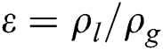 |
| a | Acceleration | m/s2 |
| CD | Drag coefficient | - |
| D0 | Droplet diameter | m |
| Ds | Spreading diameter | m |
| Db | Bag’s opening diameter | |
| Ek | Kinetic energy | J |
| Eσ | Surface tension energy | J |
| pσ | Surface tension pressure | Pa |
| p0 | Air flow pressure | Pa |
| S | Displacement | m |
| t | Time | s |
| tsh | Shear time scale | 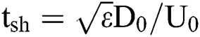 |
| U0 | Air jet flow velocity | m/s |
| v | Velocity | m/s |
| We | Weber number | 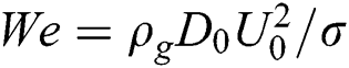 |
| ~ | Dimensionless symbol |
Liquid droplet fragmentation is an abundant phenomenon in various engineering applications, such as electro-sprayed painting, ink-jet printing, coating production, industrial, agricultural, or pressure atomized sprays. It plays an important role in the fuel supply system of liquid fuel engines, including rocket engines, gas turbine, and internal combustion engines.
Such phenomena have attracted the interest of scientists, and many works have studied either experimentally or numerically the droplet breakup, aiming to enlighten the conditions leading to the different breakup regimes and the underlying physics. The droplet breakup mechanisms have been studied through experiments [1–17] and simulations [18–27]. The studies had provided numerous useful information into the detailed processes inside and in the vicinity of the droplets during droplet breakup. More specifically, Krzeczkowski et al. [2,5] provides a droplet fragmentation map in the We–Oh plane. Further Chou et al. [6–11] clarified the boundaries between different breakup regimes. Studies reported in [9,10,15,18,20,25,26] clarified the physical mechanisms behind the breakup regimes. Dai et al. [8,13] examined the size distribution of the child droplets after the parent droplet disintegration. Flock et al. [17] identified the gas flow structure experimentally during droplet breakup. Lee et al. [10,19,21,27] examined the effect of density ratio and Quan et al. [21,22,24,26] examined the droplet drag coefficient. Strotos et al. [28,29] presented about droplet breakup and gave a universal comprehension about the critical conditions for the aerodynamic droplet breakup regimes based on a total force approach.
Although so many works have been done, the detailed breakup mechanism is still unknown. And the fundamental conclusions are a little bit far from being adopted directly to solve engineering problems.
At present, shock tube device, continuous jet device and drop tower device are the most widely used experimental devices to study droplet deformation and breakage. None of the above three methods can achieve the three key initial conditions: controllable gas velocity, zero initial droplet velocity and fixed initial droplet position. In order to meet the above experimental requirements, In this paper, a uniaxial ultrasonic standing wave suspension system is used to provide a static and non-contact fixed initial position for the droplet, which can realize the above three necessary initial conditions at the same time, and eliminate the adverse effects of external factors on the experimental results. The purpose of this paper is to predict the fragmentation characteristics of ethanol fuel droplets by experimental research, analyze the droplet breakage images, and simplify the different fragmentation modes In addition, the quantitative relationship between the deformation and motion of droplets and we was established.
Fig. 1a shows the diagrammatic sketch of the test bench. The ethanol (chromatographically pure) droplet was prepared by injecting with a syringe into the gap between the concave ultrasound transmitter and reflector; it would be levitated at one node of the standing wave of the 20 kHz acoustic. A tank of compressed air was prepared and then released by the solenoid valve to generate an impulse jet flow to blow the droplet.The Phantom Miro eX4 high-speed camera captures the fragmentation of ethanol droplets at a shooting rate of 4400 fps and an image resolution of 512 x 256 pixels. The diameter size of the ethanol droplet is controlled by the volume of the injection.The acoustic was turned off at the instance when the solenoid valve and camera was triggered.
The droplet size was controlled and then calibrated from the cameral with a ruler on the situ position of the droplet. Because of the close distance between the droplet and the outlet of the container, the forefront velocity of the impulse jet flow was calibrated in advance with the schlieren method. The initial velocity was calculated from the two neighboring images with the forefronts close to the droplet, as shown as the first two images in Figs. 1b, and 1c calibrated the situ air velocity at the droplet under various air pressure.
However, the details of the breaking droplet cannot be obtained from the schlieren method. The backlit method was utilized to study the breaking characteristics of the ethanol droplets, and the corresponding images are shown in Fig. 2.
Three different diameters around 1.0, 1.5, and 2.0 mm were tested under six Weber numbers approximately from 15 to 90 with an interval of 15, respectively. The key physical properties of ethanol and air adopted in this study were, liquid density ρl = 789 kg/m3, air density ρg = 1.025 kg/m3, surface tension σ = 0.022 N/m. The viscosity is sufficiently small (Oh << 0.01) and negligible in the Weber number range (We = 10~90) of this breakup regime.
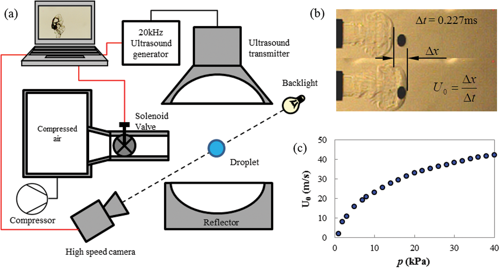
Figure 1: (a) Diagrammatic sketch of the test bench, (b) in situ air velocity measurement from neighbor video images taken by schlieren method, and (c) velocity calibration of the air jet flow under various air pressure
3.1 Breakup Morphology and Mode
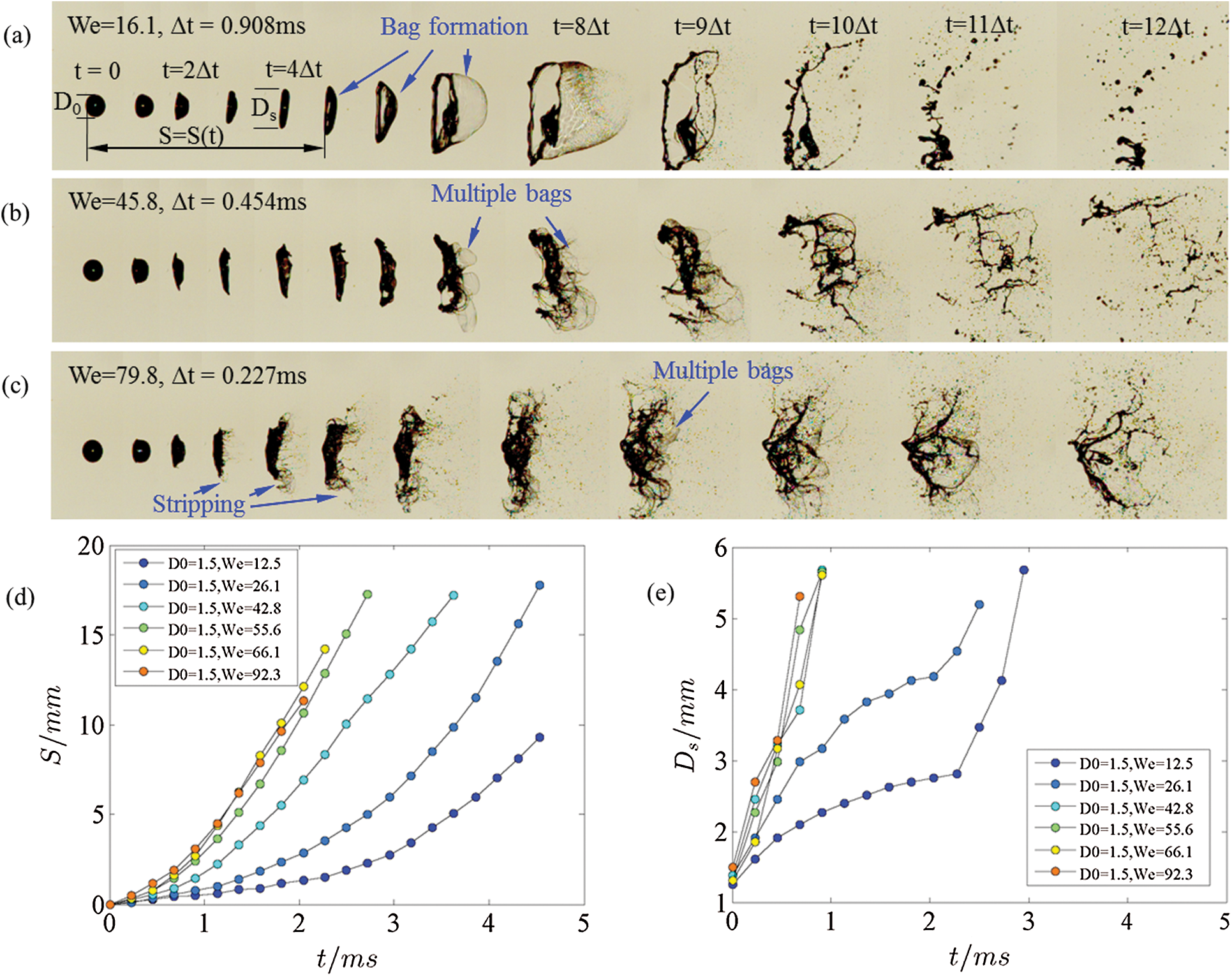
Figure 2: Aerodynamic breakup typical morphologies of breaking ethanol droplets under (a) bag, (b) multi-bag, and (c) stripping breakup modes under the Weber number of 16.1, 45.8 and 79.8, respectively; (d) displacement S of windward side versus time and (e) spreading diameter Ds of droplet versus time, with initial drop diameter D0 = 1.5 mm
At the onset of the air jet flow forefront arriving at the droplet, the windward surface of the drop is rapidly flattened. Then a thin plate is extruded out, shown as in the second and third images at individual Weber numbers in Figs. 2a–2c. Take the thickness of thin plate at  as
as  .The thickness of the plate is much thinner compared with the drop diameter, and the edge bends over downstream with the flow. The leeward side pole point stays stationary until the windward side stagnation point pulls it when the displacement S of the windward side stagnation point equals droplet’s diameter D0, S = D0, as shown in the 5th, 4th and 4th image in Figs. 2a–2c, respectively. At this point, the droplet has deformed into a “cake” with thin rims, and then the breakup process is intrigued. The breakup mode depends on the Weber number (We). They are bag, multi-bag, and shear breakups for We = 16.1, 45.8, and 79.8, respectively. Although it is called the shear breakup, the shearing only happens at the rim. The main body still breaks in the multi-bag mode.
Since the surface tension pressure ( ) in the droplet is proportional to the reciprocal radius of, so
  at the center of the “cake.” The “cake” is then inflated, and a bag(s) are formed to resist the air pressure by decreasing the surface curvature. The hemispherical bag with a diameter equal to the spreading diameter (Ds) has the maximum
  for the single-bag breakup, when the Young-Laplace equation gives
  . The bag will break up if the flow pressure
  , where
  , when the situ Weber number
  . As the
  increases, the “cake” seeks a smaller bag’s opening diameter Db to increase the
  , when n bags could form along the diameter Ds,
  , and
, and 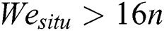 . It is the bag-stamen breakup mode when n = 2, and multi-bag mode when n > 2. Four bags were formed in the case of We = 45.8 in Fig. 2b. Strotos et al. [29] had well explained the dependency of the critical Weber number separating different breakup regimes.
Fig. 2d illustrates the displacement (S) of the windward side stagnation point of the D0 = 1.5 mm ethanol droplet. The S increases exponentially with time and grows faster at higher Weber numbers. Fig. 2e shows the spreading diameter Ds of the droplets. The Ds also increases with time, however, logarithmically at We < 30 conditions before the bags burst. When We > 42, Ds rises almost linearly with time and seems to be hardly affected by Weber number.
It is worth mentioning that the S = S(t) and Ds = Ds(t) curve clusters of the D0 = 1.0 mm and D0 = 2.0 mm are similar to the case of D0 = 1.5 mm and not shown in the paper.
3.2 Simple Scaling of the Kinematic Parameters
3.2.1 Scaling of Displacement S and Spreading Diameter Ds
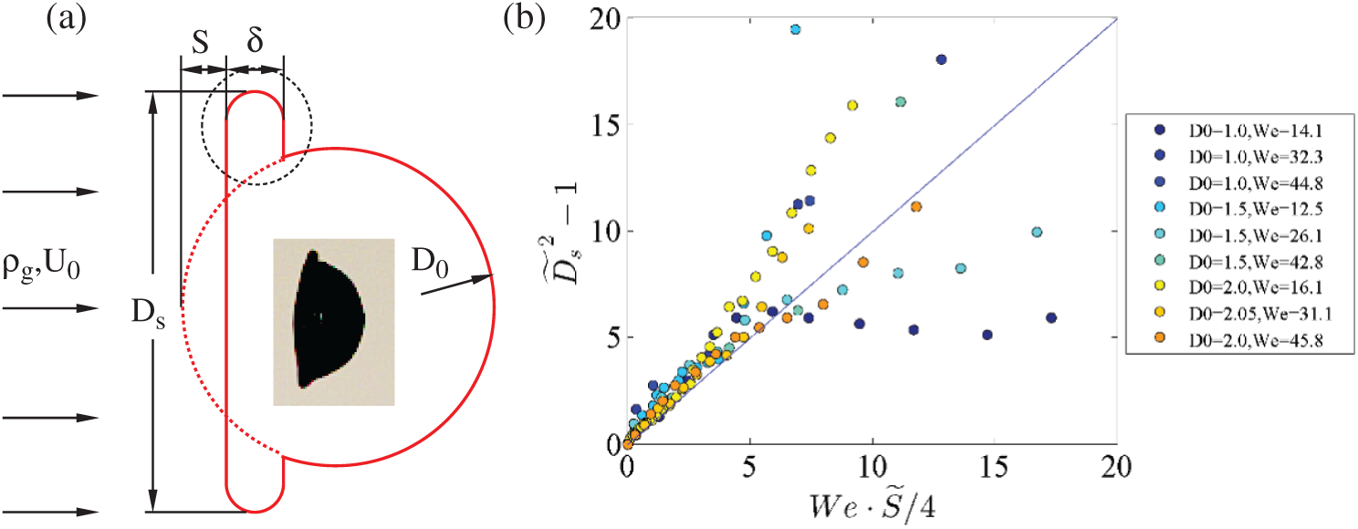
Figure 3: (a) Modeling of the initial deformation of the ethanol drop and (b) the resulting relationship between the dimensionless spreading diameter  and the dimensionless displacement
For the different ethanol droplets with an initial diameter varying from 1.0 and 1.5 to 2.0 mm, the displacement S of the windward side stagnation point, as defined in Fig. 2a and Fig. 3a, exhibits to increase exponentially with time and the Weber number, as seen in Fig. 2d; and the spreading diameter Ds of the droplet shows similar characteristics with that of S. Although S and Ds are both functions of time t, they are connected by the inner flow or shape oscillation of the drop by the law of mass conservation. Thus before we deriving the proper scaling of S = S(t) and Ds = Ds(t), we firstly put the time factor aside and calculate the mathematical expression of the function Ds = f(S).
For the low weber (<50) number cases, no shear breakup happens at the rim, and noticing that the windward side of the drop moves leeward and a plate is extruded while the leeward side remains stationary, between the instants of the air jet flow impacting on the drop and the windward side meeting the leeward side, the ethanol mass is squeezed from windward drop segment (the mass between the dashed arc and the left solid line in Fig. 3a into the plate rim (with the thickness defined as δ). In this process the kinematic work Ek of the air jet imposing in the distance S on the drop is 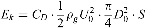 , and the surface tension potential increase is
 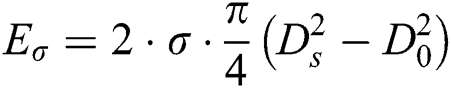 . Neglecting the kinematic energy of the internal flow of the drop, we establish the energy balance that
  , then further tidy the two formula and we get the dimensionless relationship between Ds and S displaying
 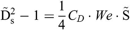 , where the upper nod is the dimensionless symbol denoting
  and
and  , respectively. Since the wind acts on Ds while we here only count the D0, Re is in the order of 100. According to the CD-Re relation curve of the spherical turbulence, the value of CD is taken as 1. Thus the drag coefficient CD is selected as 1, and then we get the following function

Fig. 3b gives the curves assembled in the form of Eq. (1), showing the model perfectly explains the relation between Ds and S. The curves collapse down into a line with the slope equals 1.0 before the critical point when  , i.e.,
  and
and  . The droplet could be inferred to remain integrity within the critical point, and beyond this point, it proceeds in a rapid splashing breakup mode. It is worth mentioning that most of the cases tested in this study fell into the rapid breakup mode before the windward side of the droplet went through the droplet diameter, where
  and We = 20.
3.2.2 Scaling of Rim Thickness Ds
Based on the model shown in Fig. 3a, we further supposed a submodel to scale the thickness of the rim, as shown in Fig. 4a, which gives the details of the rim in the dashed circle in Fig. 3a. Although the rim suffers a rather complex flow field, the flow pressure could be sorted into categories, one is the positive flow pressure, and the other is negative flow-by pressure. The surface tension pressure balances these two flow pressures. Thus, from Bernoulli theory and Young-Laplace equation, we get the pressure-balancing equations as
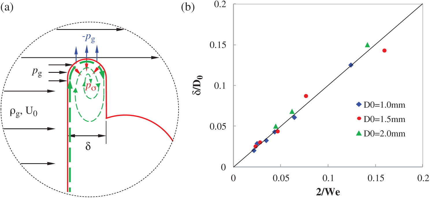
Figure 4: Rim pressure balance and inner flow model (a) schematics and (b) scaling of dimensionless rim thickness  versus 2/We

where  is the thickness of the plate rim, and
  is the spreading diameter of the ethanol droplet.
  is the surface tension coefficient of ethanol.
Since  , neglecting
  then from Eq. (2), we could obtain the dimensionless rim thickness:

Fig. 4b shows that the experimental data agree well with the theoretical predictions from Eq. (3). Then we may further address that quick breakup of the droplet occurs at the position where  .
.
We found another interesting phenomenon is that, if we assume the mass that extruded from the windward surface layer flow into the rim along the surface, as shown as the thick green dashed arrow in Fig. 4a, we could write the continuous equation to describe the flow as:

where v is the speed of the windward surface. From the following section, we know  , then substituting Eq. (7) into Eq. (4), with the boundary condition Ds = 1 @ t=0, tidying the equation up finally gives
 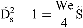 . This is just Eq. (1). This consistency of the energy balance analysis in the previous section and kinematic analysis in this section validates the assumption that the ethanol mass at the windward side flows into the rim along with the surface layer. Thus, that would form a vortex ring in the rim, shown as the thin green dashed arrow in Fig. 4a, the authentic vortex ring is stretched as simulated in the work of Strotos et al. [30].
3.2.3 Scaling of Displacement S
In this section, we attempt to establish the dimensionless function of displacement  and time
  , where
 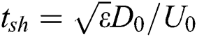 , which is the shear timescale proposed by Nicholls et al. [31], and
  is the density ratio of the ethanol and air.
From the above analysis, it is clear that the windward surface is invaded by the jet flow to deform and break, while the surface tension retains the droplet’s integrity. Since the pressure exerting on the rim is helpless to the movement of the windward stagnation point, i.e., the tab point to calculate droplet’s displacement S, only the flow pressure imposing on the sectional area  is effective. Then neglecting the plate mass gives the dynamic equation on the droplet

Recognizing the above formula gives:

The velocity and time are dimensionless with  , and CD is taken 1.0 as in the Section 3.2.1. Then the Eq. (6) could be nondimensionalized as:

This equation infers the dimensionless acceleration  merely a function of Weber number.
  is a constant at a given Weber number. Then the nondimensional displacement
  could be simply expressed as
  . Fig. 5 shows the experimental
  and its fitting curve.

The experimental  and the theoretical one is in the same scaling. However, the former one is eight times of the theoretical one. The linear relationship implies the movement of the droplet obeys free acceleration rule in the impulse jet flow.
Surface tension force could be neglected for higher We numbers. In this case, the surface tension item at the right-hand side of Eq. (6) is ignorable. Thus the model is valid despite of that whether the windward stagnation point reaches the leeward pole point or not.
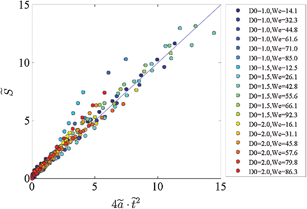
Figure 5: Experimental  and its fitting curve
3.2.4 Rapid Breakup at High Weber Numbers
From Section 3.2.2 we know that along-surface radical ethanol flow is responsible to the spreading speed of the plate rim, although the rim is crooked for lacking of mass support at the leeward side, the movement on the flow direction is independent with the spreading of Ds in the radical direction. Since the rim thickness  decreases with Weber number, the vortex ring in Fig. 4a would be overstretched, and the plate would perform as a two-dimensional film, the critical Weber number is around 50 in this study. In this case, the positive pressure of the airflow is converted to the flow pressure of the inner flow. Thus we get
  , and so
  , where Us is the spreading velocity of Rs = Ds/2. Then integrating Us with
  dt under the boundary condition
  @ t = 0, we have the function of Ds = Ds(t) presenting
  . Fig. 6 plots the experimental
  data and shows good linearity between
  , however, with the slope of 4 rather than the theoretical one. Thus, the relationship between
  is expressed as:

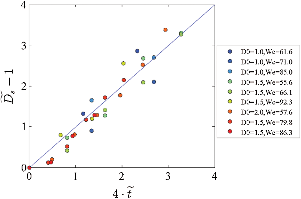
Figure 6: Dimensionless spreading diameter versus dimensionless time
In the present work, the breakup characteristics of ultrasonic levitated ethanol droplets have been experimentally investigated, and then the physical models have been established to explain the breakup behaviors. The conclusions of this study are as follows.
The movement of the windward side of the droplet in the impulse jet flow obeys the free acceleration rule in the impulse jet flow. The dimensionless displacement  is a simple function of dimensionless acceleration and dimensionless time, which could be expressed as
  .
.
In the breakup process, a thin plate is extruded before the droplet breaks, the dimensionless plate thickness  is a function of Weber number, i.e.,
  . The diameter of the plate, i.e., the spreading diameter DS, is also a function of Weber number and displacement, shown in nondimensional form as
  . The breakup process bursts at the position where
  .
.
The effects of surface tension are weak when We > 50, the ethanol along the windward surface is squeezed out with a constant velocity of  , and dimensionless spreading diameter
  performs a single parameter function of
  , i.e.,
  .
.
Funding Statement: The work at Xi’an Jiaotong University was supported by the National Natural Science Foundation China (Nos. 51576159 and 91741110) and the Shaanxi Provincial Key R&D Plan (Grant Nos. 2019ZDLGY15-10 and 2019ZDLGY15-07).
Conflicts of Interest: The authors declare that they have no conflicts of interest to report regarding the present study.
1. Kékesi, T., Amberg, G., Prahl Wittberg, L. (2014). Drop deformation and breakup. International Journal of Multiphase Flow, 66, 1–10. DOI 10.1016/j.ijmultiphaseflow.2014.06.006. [Google Scholar] [CrossRef]
2. Krzeczkowski, S. A. (1980). Measurement of liquid droplet disintegration mechanisms. International Journal of Multiphase Flow, 6(3), 227–239. DOI 10.1016/0301-9322(80)90013-0. [Google Scholar] [CrossRef]
3. Hsiang, L. P., Faeth, G. M. (1992). Near-limit drop deformation and secondary breakup. International Journal of Multiphase Flow, 18(5), 635–652. DOI 10.1016/0301-9322(92)90036-G.
4. Hsiang, L. P., Faeth, G. M. (1993). Drop properties after secondary breakup. International Journal of Multiphase Flow, 19(5), 721–735. DOI 10.1016/0301-9322(93)90039-W.
5. Hsiang, L. P., Faeth, G. M. (1995). Drop deformation and breakup due to shock wave and steady disturbances. International Journal of Multiphase Flow, 21(4), 545–560. DOI 10.1016/0301-9322(94)00095-2. [Google Scholar] [CrossRef]
6. Chou, W. H., Hsiang, L. P., Faeth, G. M. (1997). Temporal properties of drop breakup in the shear breakup regime. International Journal of Multiphase Flow, 23(4), 651–669. DOI 10.1016/S0301-9322(97)00006-2. [Google Scholar] [CrossRef]
7. Chou, W. H., Faeth, G. M. (1998). Temporal properties of secondary drop breakup in the bag breakup regime. International Journal of Multiphase Flow, 24(6), 889–912. DOI 10.1016/S0301-9322(98)00015-9.
8. Dai, Z., Faeth, G. M. (2001). Temporal properties of secondary drop breakup in the multi-bag breakup regime. International Journal of Multiphase Flow, 27(2), 217–236. DOI 10.1016/S0301-9322(00)00015-X. [Google Scholar] [CrossRef]
9. Liu, Z., Reitz, R. D. (1997). An analysis of the distortion and breakup mechanisms of high speed liquid drops. International Journal of Multiphase Flow, 23(4), 631–650. DOI 10.1016/S0301-9322(96)00086-9. [Google Scholar] [CrossRef]
10. Lee, C. H., Reitz, R. D. (2000). An experimental study of the effect of gas density on the distortion and breakup mechanism of drops in high speed gas stream. International Journal of Multiphase Flow, 26(2), 229–244. DOI 10.1016/S0301-9322(99)00020-8. [Google Scholar] [CrossRef]
11. Cao, X. K., Sun, Z. G., Li, W. F., Liu, H. F., Yu., Z. H. (2007). A new breakup regime of liquid drops identified in a continuous and uniform air jet flow. Physics of Fluids, 19(5), 057103. DOI 10.1063/1.2723154. [Google Scholar] [CrossRef]
12. Zhao, H., Liu, H. F., Li, W. F., Xu, J. L. (2010). Morphological classification of low viscosity drop bag breakup in a continuous air jet stream. Physics of Fluids, 22(11), 114103. DOI 10.1063/1.3490408.
13. Zhao, H., Liu, H. F., Xu, J. L., Li, W. F., Lin, K. F. (2013). Temporal properties of secondary drop breakup in the bag-stamen breakup regime. Physics of Fluids, 25(5), 054102. DOI 10.1063/1.4803154. [Google Scholar] [CrossRef]
14. Opfer, L., Roisman, I. V., Tropea, C. (2012). Aerodynamic fragmentation of drops: Dynamics of the liquid bag. 12th Triennial International Conference on Liquid Atomization and Spray Systems, pp. 1–8, Heidelberg, Germany.
15. Opfer, L., Roisman, I. V., Venzmer, J., Klostermann, M., Tropea, C. (2014). Droplet-air collision dynamics: Evolution of the film thickness. Physical Review E, 89(1). DOI 10.1103/PhysRevE.89.013023. [Google Scholar] [CrossRef]
16. Sojka, P. E., Guildenbecher, D. R. (2011). Experimental investigation of aerodynamic fragmentation of liquid drops modified by electrostatic surface charge. Atomization and Sprays, 21(2), 139–147. DOI 10.1615/AtomizSpr.2011003299.
17. Flock, A. K., Guildenbecher, D. R., Chen, J., Sojka, P. E., Bauer, H. J. (2012). Experimental statistics of droplet trajectory and air flow during aerodynamic fragmentation of liquid drops. International Journal of Multiphase Flow, 47, 37–49. DOI 10.1016/j.ijmultiphaseflow.2012.06.008. [Google Scholar] [CrossRef]
18. Han, J., Tryggvason, G. (2001). Secondary breakup of axisymmetric liquid drops. II. Impulsive acceleration. Physics of Fluids, 13, 1554–1565. [Google Scholar]
19. Aalburg, C. (2002). Deformation and breakup of round drop and nonturbulent liquid jets in uniform crossflows. (Ph.D. Thesis). Aerospace Engineering and Scientific Computing, University of Michigan, 154. [Google Scholar]
20. Khosla, S., Smith, C. E. (2006). Detailed understanding of drop atomization by gas crossflow using the volume of fluid method. Toronto, Canada: ILASS Americas. [Google Scholar]
21. Quan, S., Schmidt, D. P. (2006). Direct numerical study of a liquid droplet impulsively accelerated by gaseous flow. Physics of Fluids, 18(10), 103103. DOI 10.1063/1.2363216. [Google Scholar] [CrossRef]
22. Wadhwa, A. R., Magi, V., Abraham, J. (2007). Transient deformation and drag of decelerating drops in axisymmetric flows. Physics of Fluids, 19(11), 113301. DOI 10.1063/1.2800038. [Google Scholar] [CrossRef]
23. Xiao, F., Dianat, M., McGuirk, J. J. (2012). LES of single droplet and liquid jet primary breakup using a coupled level set/volume of fluid method. 12th ICLASS, Heidelberg, Germany.
24. Khare, P., Yang, V. (2013). Drag coefficients of deforming and fragmenting liquid droplets. The Journal of the International Institutes for Liquid Atomization and Spray Systems, ILASS Americas. [Google Scholar]
25. Jalaal, M., Mehravaran, K. (2014). Transient growth of droplet instabilities in a stream. Physics of Fluids, 26(1), 012101. DOI 10.1063/1.4851056. [Google Scholar] [CrossRef]
26. Jain, M., Prakash, R. S., Tomar, G., Ravikrishna, R. V. (2015). Secondary breakup of a drop at moderate Weber numbers. Proceedings of the Royal Society A: Mathematical, Physical and Engineering Sciences, 471(2177), 20140930. DOI 10.1098/rspa.2014.0930. [Google Scholar] [CrossRef]
27. Yang, W., Jia, M., Sun, K., Wang, T. (2016). Influence of density ratio on the secondary atomization of liquid droplets under highly unstable conditions. Fuel, 174, 25–35. DOI 10.1016/j.fuel.2016.01.078. [Google Scholar] [CrossRef]
28. Strotos, G., Malgarinos, I., Nikolopoulos, N., Gavaises, M. (2016). Predicting droplet deformation and breakup for moderate Weber numbers. International Journal of Multiphase Flow, 85, 96–109. DOI 10.1016/j.ijmultiphaseflow.2016.06.001. [Google Scholar] [CrossRef]
29. Strotos, G., Malgarinos, I., Nikolopoulos, N., Gavaises, M., Nikas, K. S. et al. (2018). Determination of the aerodynamic droplet breakup boundaries based on a total force approach. International Journal of Heat and Fluid Flow, 69, 164–173. DOI 10.1016/j.ijheatfluidflow.2018.01.001. [Google Scholar] [CrossRef]
30. Strotos, G., Malgarinos, I., Nikolopoulos, N., Gavaises, M. (2016). Aerodynamic breakup of an n-decane droplet in a high temperature gas environment. Fuel, 185, 370–380. DOI 10.1016/j.fuel.2016.08.014. [Google Scholar] [CrossRef]
31. Nicholls, J. A., Ranger, A. A. (1969). Aerodynamic shattering of liquid drops. AIAA Journal, 7(2), 285–290. DOI 10.2514/3.5087. [Google Scholar] [CrossRef]
 | This work is licensed under a Creative Commons Attribution 4.0 International License, which permits unrestricted use, distribution, and reproduction in any medium, provided the original work is properly cited. |