DOI: 10.32604/EE.2021.014143
ARTICLE
Analysis of Electromagnetic Performance of Modulated Coaxial Magnetic Gears Used in Semi-Direct Drive Wind Turbines
1School of Mechatronics and Vehicle Engineering, East China Jiaotong University, Nanchang, 330000, China
2School of Basic Science, East China Jiaotong University, Nanchang, 330013, China
*Correspondence Author: Jungang Wang. Email: sduhys@163.com
Received: 03 September 2020; Accepted: 09 October 2020
Abstract: Wind turbine is a key device to realize the utilization of wind energy, and it has been highly valued by all countries. But the mechanical gear transmission of the existing wind power device has the disadvantages of high vibration and noise, high failure rate, and short service time. Magnetic field modulation electromagnetic gear transmission is a new non-contact transmission method. However, the conventional modulation magnetic gear has low torque density and torque defects with large fluctuations. In order to overcome the gear transmission problems of the existing semi-direct drive wind power generation machinery and improve the electromagnetic performance of the traditional magnetic gear transmission, this paper proposes a new transmission scheme of a non-contact semi-direct drive wind generator with a surface mount Halbach array modulated magnetic gear method, and considers the electromagnetic properties of the semi-direct drive modulation magnetic gear of the wind turbine. The finite element software is used to construct the model of the surface-mounted Halbach array magnetic gear and the conventional gear, analyzed the distribution of magnetic field lines of the two magnetic gears, calculated the air gap magnetic flux density of the inner and outer air gap, and obtained the main harmonics of the inner and outer air gap magnetic density; calculated the static torque and steady-state operating torque of the inner and outer rotors in the model, compared the air gap flux density, harmonics and torque of the magnetic gears. The simulation results show that the magnetic field modulation type magnetic gear of the surface mount Halbach array magnetic gear method improves the magnetic induction waveform of the inner and outer air gap, reduces the pulse torque fluctuation, and has a 60% higher static torque. Applying it to semi-direct drive wind power generation equipment not only overcomes the shortcomings of mechanical gears, but also has higher electromagnetic performance. Therefore, the surface-mounted Halbach array modulated magnetic gear can be used to replace the mechanical gearbox in the semi-direct drive wind power generation equipment.
Keywords: Wind power generation; gear box; magnetic gear; finite element analysis
With the increasing demand for energy in human society, wind energy has received attention as a pollution-free and renewable new energy [1]. The development of wind power transmission technology is relatively rapid, and there are various transmission solutions to achieve constant speed or variable speed wind power turbines. According to different types of transmission chain, it can be divided into direct drive mode without gear box and drive mode with gear box. As shown in Fig. 1, the semi-direct drive wind turbine is a mechanical gearbox driven by an impeller, which transmits torque to a generator to generate electricity. The semi-driven wind turbine combines the advantages of the direct-driven and doubly-fed generators, such as fast speed, small size and compact structure, that makes semi-direct-drive wind turbines more versatile and efficient for a wider range of uses [2–4]. However, the gearbox is driven by mechanical contact gears. Due to the structural limitations of the gears themselves, there is often cause gear tooth fracture [5], tooth surface wear or scoring [6,7], tooth surface fatigue [8,9], tooth surface plastic deformation [10,11] and other problems. This causes frictional losses, noise, and vibration in semi-direct-drive wind turbines, and requires intermittent maintenance [12–15].
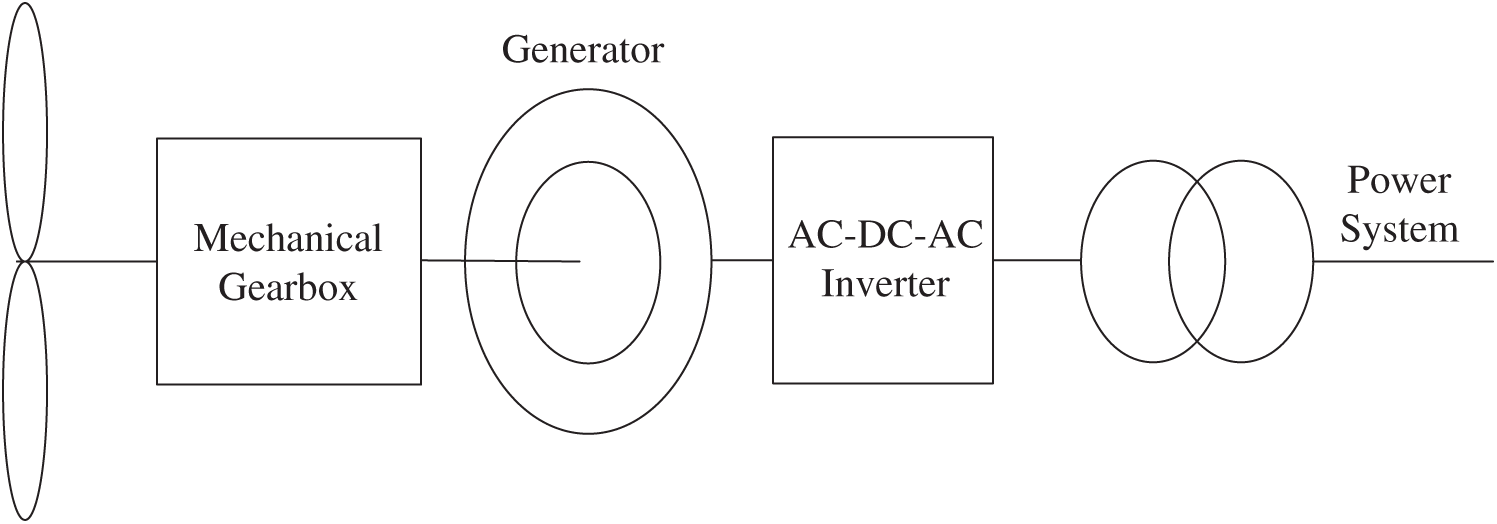
Figure 1: Mechanical geared semi-direct drive wind turbine
In recent years, the concept of magnetic gears has received extensive attention from scholars. Because of the theory of magnetic field modulation proposed by Atallah et al. [16], magnetic gears achieve bidirectional modulation of low-speed and high-speed magnetic fields under the influence of magnetic modulator blocks. Furthermore, the electromechanical energy conversion is performed through the coupling of the harmonic magnetic field [17]. The inner and outer rotors are modulated by magnetic field coupling for transmission, and the inner and outer rotors operate without contacting each other during transmission. That makes magnetic gears have the advantages of frictionless vibration, no lubrication maintenance, no noise, and compact structure compared with mechanical gears [18–20]. If magnetic gears are used instead of mechanical gearboxes in a semi-direct-drive wind turbine, the failure rate of the transmission mechanism will be reduced, and the reliability of the wind power generation equipment will be improved.
In order to improve the torque density and electromagnetic performance of the magnetic gear. Some scholars have proposed for magnetic gear permanent magnet material type, magnetic gear structure, permanent magnet installation method, magnetic modulator ring profile and other aspects of the improvement. For example, Chen et al. [21] analyzed and compared several permanent magnet materials, and finally concluded that rare earth permanent magnet materials have better performance and lower cost under the same structure size than non-rare earth permanent magnet materials. Zhang et al. [22], after quantitative analysis of coaxial magnetic gears, found that the influence of inner rotor permanent magnet thickness on torque capacity is greater than that of outer rotor permanent magnet, and torque is more sensitive to the air gap length of the inner rotor, etc., but did not give the best design method for coaxial magnetic gears. Liu et al. [23] proposed a buried outer rotor topology, which can improve the integrity and mechanical strength of the gear when the magnetic gear is running at high speed, but this will also reduce the amount of magnets in the outer rotor and weaken the torque density. Kim et al. [24] proposed a new type of magnetic modulator blocks, which improved the torque density but its torque ripple also increased, which makes the magnetic gear very unstable when transferring torque. Cansiz et al. [25] proposed to use high-temperature superconductors to be installed in the modulation ring. According to the non-magnetic characteristics of high-temperature superconductors, the torque transmission performance is increased. However, this superconductor is not suitable for use in wind turbines because of its harsh application environment and high price. The compound differential coaxial magnetic gear is proposed by Gardner et al. [26]. Multistage designs can achieve much higher net gear ratios with much less of a torque density penalty, especially as the number of stages increases, but this entails greater complexity. Because semi-direct-drive wind power generation equipment requires volume, this solution has not been adopted. Jing et al. [27] proposed eccentric magnetic harmonic gears. It can achieve high speed ratio transmission and large torque output by modulating the air gap length between permanent magnets. However, according to the periodic deformation of the flex spline of the eccentric magnetic harmonic gear, alternating stress is generated, which is prone to fatigue damage, and has poor heat dissipation conditions, which is not suitable for use in wind power generation equipment.
To compensate for the shortcomings of mechanical gearing and to improve the electromagnetic properties of magnetic gears, in this paper, magnetic gears using a Halbach array of permanent magnet mountings are proposed to be placed between the impeller and generator of a wind turbine, as shown in Fig. 2, in place of conventional mechanical gears. The permanent magnet installation method using Halbach array is proposed, which is applied to the magnetic gear to increase the magnetic flux in the air gap between the inner and outer rotors, so that the inner and outer rotors can better couple and transmit torque, and reduce the pulse fluctuation, so that the transmission is more stable. This makes it an effective replacement for mechanical gearboxes in semi-direct drive wind turbines.
The magnetic gears proposed in this paper are constructed with Halbach arrays on both the inner and outer rotors. First, modeling and analysis of the structure and the distribution of magnetic susceptibility lines by means of finite element software. Then make simulation analysis of gears in static and steady-state operation. According to the comparison with conventional magnetic gears in terms of air gap magnetic field distribution and harmonic content, it is found that the Halbach array magnetic gear has higher torque density, smaller pulse torque fluctuation, higher output speed and more stable output, and is more suitable to replace the mechanical gearbox of semi-direct drive wind turbines.
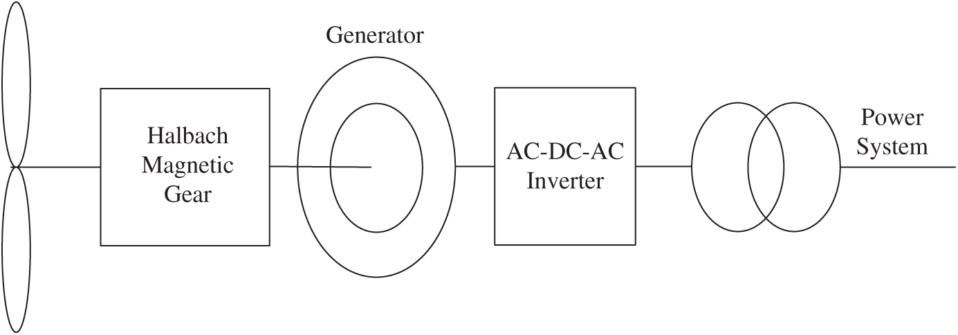
Figure 2: Halbach magnetic geared semi-direct drive wind turbine
2 Magnetic Gear Model and Theoretical Analysis
In this paper, Ansoft software is used to model and analyze the magnetic gears. As shown in Fig. 3 below, the cross-sectional model of the magnetic gear. The conventional magnetic gear is composed of an inner rotor, an outer rotor, and a magnetic modulator ring. The permanent magnets on the inner and outer rotors are typically made of NdFeB, which is mounted on the rotor yoke in a table-mounted manner. The permanent magnet is magnetized in the radial direction and magnetically coupled through the magnetic modulator ring. The magnetic adjusting pole block is made of silicon steel plate axially stacked, and the external epoxy resin mold is used to fix the magnetic adjusting pole block. The silicon steel sheet is also coated with an insulating layer, which greatly prevents eddy current phenomena.
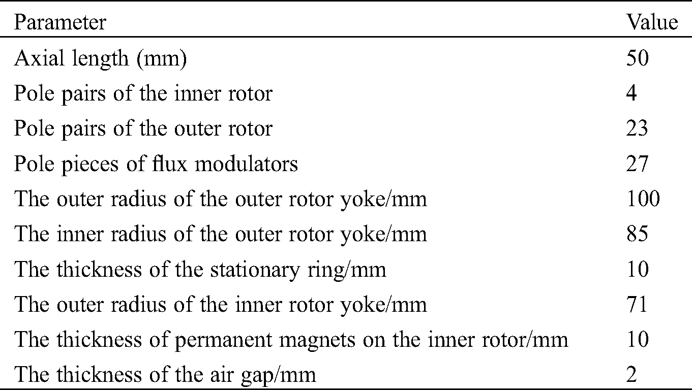
Fig. 4 is the Halbach array magnetic gear proposed in this paper, the size is the same as the conventional magnetic gear of Fig. 3. Since the size and structure of the two magnetic gears are basically the same, the related parameters of their structure are shown in Tab. 1. The difference lies in the different arrangement of the permanent magnets on the rotor. The Halbach array is an array structure formed by multiple magnets with different magnetization methods. In order to show the magnetic field of the magnetic gears more clearly, arrows are used in the picture to indicate the direction of magnetization of the magnets. As can be seen, one outer rotor pole is split into four magnets, while the pair of inner rotor poles is split into six magnets. Overall, the number of pole pairs on the inner and outer rotors remains 4:23. In this way, installing permanent magnets can create a magnetic field closer to the sine wave distribution in the surrounding space. Moreover, Halbach magnet arrays can establish a stronger magnetic field on one side of their particular space and a weaker one on the other. Such self-shielded magnetization characteristics will result in a stronger coupling of the inner and outer rotor magnetic fields.
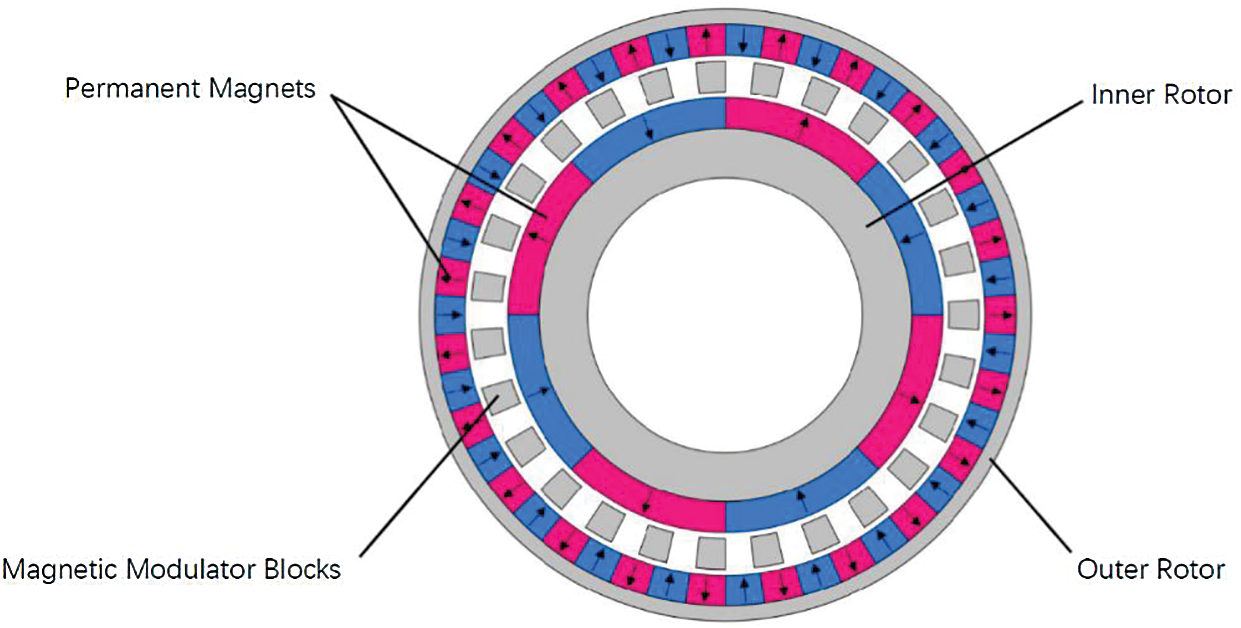
Figure 3: Conventional magnetic gear model
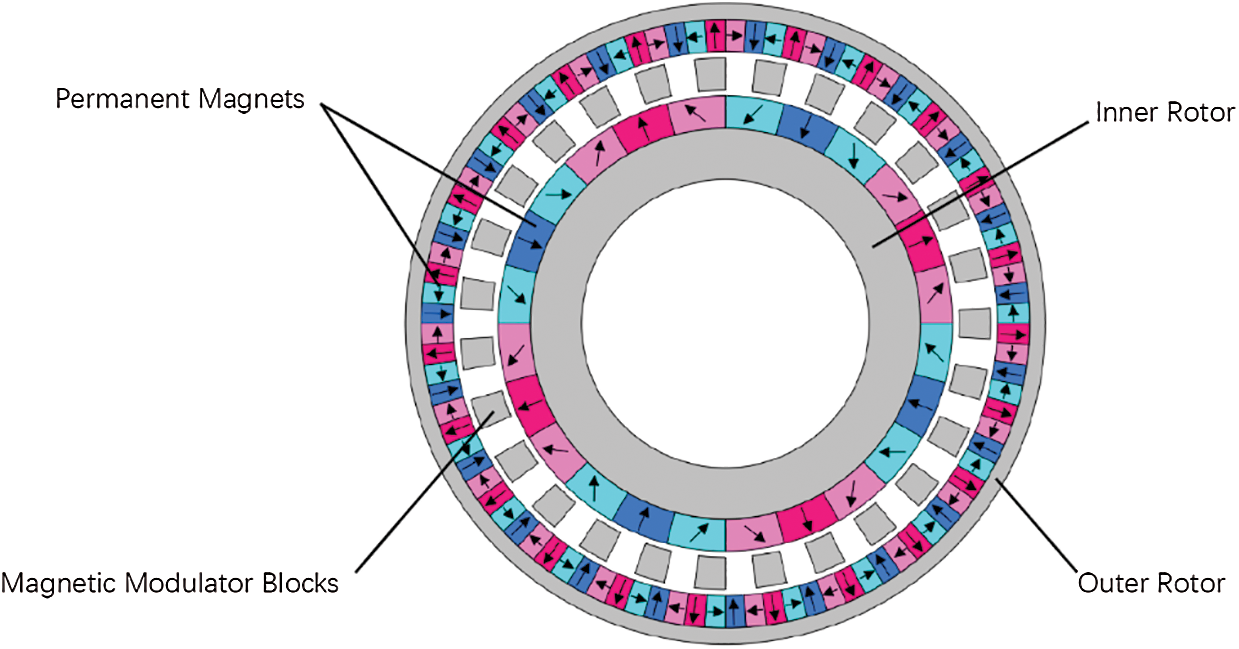
Figure 4: Halbach array magnetic gear model
Table 1: Parameters for the magnetic gear
In magnetic gears, the relationship between the number of adjusting magnets and the number of pole pairs of permanent magnets is as follows:

Pin and Pout were the pairs of permanent magnet poles assembled on the inner and outer rotors respectively; NS was the number of magnetizing blocks. When the model is running, the magnetic control rings remain stationary and the inner and outer rotors rotate in opposite directions. Because the inner and outer rotor iron yokes and the magnetic pole pieces are insulated and coated with silicon steel sheets axially laminated, it prevents the occurrence of eddy currents greatly.
The magnetic inductance intensity in the air gap, without considering the action of the magnetic modulation ring, can be expressed as


In the equation: r and θ were the polar moment and phase angle of the observation point in the polar coordinate system; Am and Bm were the Fourier coefficients and they were only related to the polar moment r; m was the number of harmonics and P was the logarithm of the magnetic pole, ωr was the magnetic pole angular velocity, and θ0 was the initial rotor angle.
After the introduction of the demagnetizing ring and after the magnetic field modulation effect, the magnetic induction strength produced by the rotor permanent magnet field is


The magnetic field modulation ring primarily affects the internal and external air-gap magnetic fields so that the magnetic fields excited by the internal and external permanent magnets can be effectively coupled for torque transfer.
The magnetic field modulation ring primarily affects the magnetic field harmonics generated by the internal and external rotors. These same-pole synchronous harmonic pairs can be effectively coupled to generate stable magnetic torque to achieve torque transmission.
The magnetic field contains a large number of harmonic components, and their spatial pole pairs can be represented as

In the air gap, there is a specific number of rotational speed and spatial pole pairs for the harmonic component. The rotational speed corresponding to the harmonic component of the magnetic field can be expressed as

That ωm,k was the spatial harmonic component angular velocity, ωr was the magnetic gear rotor rotation speed and ωs was the magnetic modulation ring rotation speed.
While k = 0, the harmonic magnetic field angular velocity is equivalent to the rotor angular speed. While k ≠ 0, it represents the angular velocity of different harmonic magnetic fields. While m = 1, k = −1, the most important harmonics are generated by the inner and outer rotors through the modulating ring magnetic field. According to Eq. (7), the harmonic component angular velocity is

In fact, due to the limitation of the strength and rigidity of the magnetic gear, the modulation ring is usually fixed. Therefore, the gear ratio (Gr) of the coaxial magnetic gear is

It is calculated that the transmission ratio of the two magnetic gears mentioned in this paper is 5.75.
3 Comparison of Magnetic Field between Conventional Magnetic Gear and Halbach Magnetic Gear
3.1 Magnetic Line Distribution
The software analysis of the two magnetic gear models can be used to obtain the distribution of magnetic inductance lines shown in Fig. 5. It can be clearly seen that the magnetic lines of induction in the iron yoke of the inner and outer rotors are significantly sparser in the Halbach array magnetic gear model than in the conventional magnetic gear. However, the magnetic lines of induction between the inner and outer rotors of the Halbach array magnetic gear are obviously denser than conventional magnetic gears. This phenomenon is a result of the unique self-shielded nature of the permanent magnet in the Halbach array mounting method, which enhances the magnetic field between the inner and outer rotor, i.e., enhances the magnetic field unilaterally, and enhances the transfer torque by coupling through the tuned pole block ring. This redesigns the magnetic gears in such a way that the thickness of the yoke on the inner and outer rotors can be reduced, which reduces the size of the magnetic gears and improves the performance of the wind turbine.
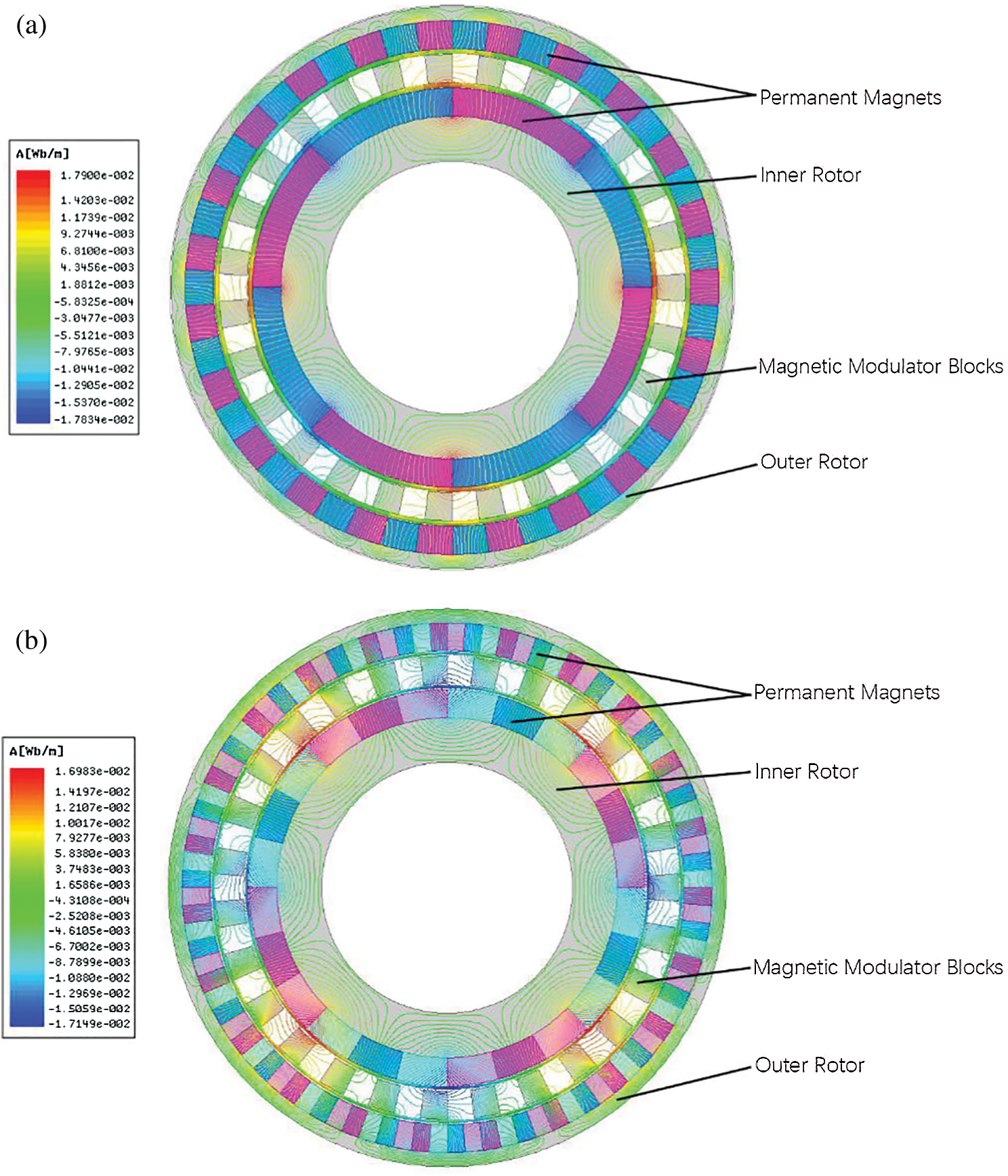
Figure 5: Magnetic line distribution of two types of magnetic gears (a) Conventional magnetic gears. (b) Halbach array magnetic gears
Fig. 6 shows the comparison of tangential and radial magnetic induction in the internal and external air gaps of the two magnetic gears. The figures show that the waveforms are approximately sinusoidal. The waveform diagram shows the interaction of the 4 pairs of inner rotors as well as the 23 outer rotor permanent magnets. Although there are harmonic components and the presence of the magnetic pole piece has caused many magnetic field spikes, it still maintains 4 or 23 magnetic field cycles as a whole.
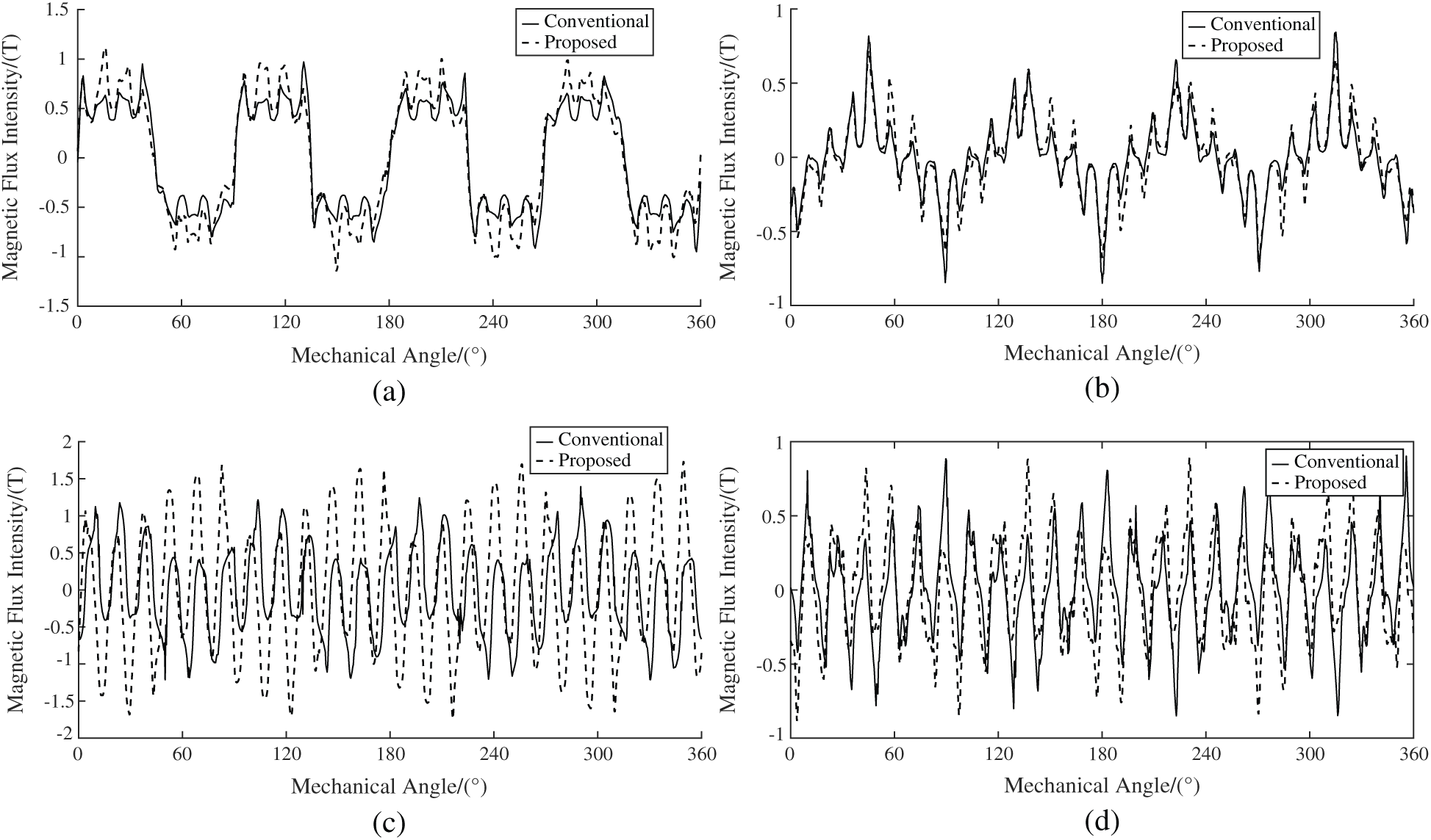
Figure 6: Air gap magnetic induction (a) Air gap flux density waveform inner radial. (b) Air gap flux density waveform inner tangent. (c) Air gap flux density waveform outer radial. (d) Air gap flux density waveform outer tangent
The spatial harmonic spectrum of the air-gap magnetic susceptibility intensity is obtained by Fourier transform of the breath magnetic susceptibility data by mathematical calculation software in Fig. 7. In the spatial harmonic spectra of the inner radial and tangential air-gap magnetic susceptibility in Figs. 7a and 7b, the number of magnetic field harmonics such as 4, 28, 31 and 50, which are favorable for torque, are enhanced in the Halbach array arrangement. The harmonic orders of the magnetic field such as 12, 20, 36, 42, 44 are suppressed, and these harmonic orders are also factor that cause pulsating torque. Similarly, in the spatial harmonic spectra of the radial and tangential air-gap magnetic susceptibility of the outer layer in Figs. 7c and 7d, the number of magnetic field harmonics 4, 23, 31, 50, etc., of the Halbach array magnetic gear is greatly enhanced. And it can be seen that the 50th harmonic is the main harmonic source of torque, and the number of harmonics of the pulsating torque magnetic field such as 12, 15 and 20 is suppressed. The Halbach array magnetic gears have higher air-gap magnetic induction strength and fewer harmonics than conventional magnetic gears.
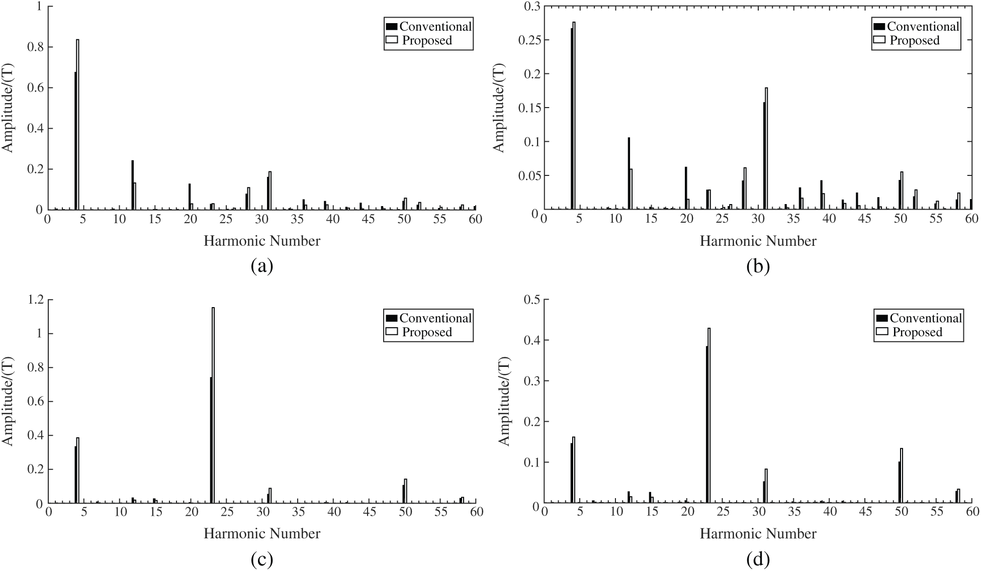
Figure 7: Air gap magnetic induction intensity spatial harmonic spectrum (a) FFT harmonic spectra of flux density inner radial component. (b) FFT harmonic spectra of flux density inner tangential component. (c) FFT harmonic spectra of flux density outer radial component. (d) FFT harmonic spectra of flux density outer tangential component
4 Torque Analysis and Comparison
Static torque is a measure of the magnetic gears by setting one rotor to stand still and not rotate and the other rotor to rotate in a fixed direction. From the Maxwell tensor method, the magnetic torque produced by this field coupling can be expressed as

Among them, Lef represented the axial length of the magnetic gear, R was the air gap radius of the inner rotor or outer rotor, μ0 was the vacuum permeability, BR and BT were the radial and tangential magnetic flux densities, respectively.
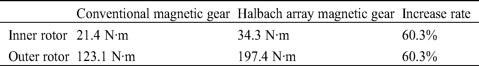
The static torque diagram of Fig. 8 is obtained by the analysis of the finite element software. It can be seen that the static torque is sinusoidal with the mechanical angle. The waveform positions of the inner and outer rotors show that the two rotors rotate in opposite directions. The maximum value of the waveform curve represents the output static torque. Furthermore, according to Tab. 2. the peak static torque of the inner rotor of the Halbach magnetic gear is 34.3 N·m, which is 60.3% higher than the 21.4 N·m of the traditional magnetic gear. The peak static torque of the outer rotor of the Halbach magnetic gear is 197.4 N·m, which is 60.3% higher than the 123.1 N·m of the traditional magnetic gear. The static torque ratio of their inner and outer rotors is equal to the gear ratio of 4:23. In addition, the static torque of the magnetic gear using the Halbach array installation method is increased by 60% compared with the conventional gear.
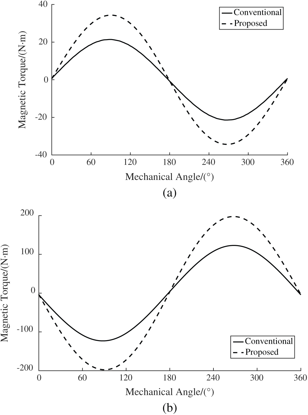
Figure 8: Static torque (a) comparison of inner rotor. (b) Comparison of outer rotor
Table 2: Comparison of static torque
Set the inner rotor of both magnetic gears in the simulation software at 40 r/min, doing clockwise rotation. The outer rotor rotates counterclockwise at 230 r/min. Obtaining the Fig. 9, dynamic torque analysis plot. It can be seen from the figure that as the mechanical angle changes, the dynamic torque of the inner rotor and the outer rotor does hardly fluctuate, which makes the working torque stable. In order to compare the torque ripple amplitude under dynamic torque, the torque ripple amplitude value Kripple can be calculated as:

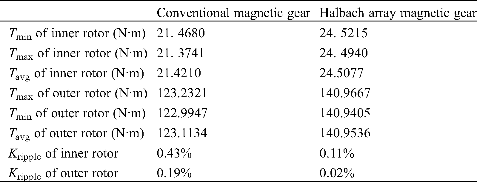
In formula (11), Tmax and Tmin were the maximum and minimum values of dynamic torque, and Tavg was the average value of dynamic torque. By calculating the data obtained in Fig. 9, the magnitude of the dynamic torque ripple amplitude of the inner and outer rotors under various designs can be quantitatively derived. Tab. 3. shows the average torque and torque ripple amplitude of the inner rotor and outer rotor of the two topology structures in this paper. The inner rotor dynamic torques of the conventional magnetic gears and the Halbach magnetic gears fluctuate in the range of 21.3741 N·m to 21.4680 N·m and 24.4940 N·m to 24.5215 N·m, respectively. The torque ripple amplitude values of the inner rotor of the two structures are 0.43% and 0.11%. The outer rotor torque fluctuates between 122.9947 N·m and 123.2321 N·m and between 140.9405 N·m and 140.9667 N·m. And the torque ripple amplitude values of the outer rotor are 0.19% and 0.02%. It can be seen that the dynamic torque of the Halbach magnetic gears fluctuates even less. It is more stable than the conventional magnetic gear, and the dynamic running torque is significantly improved compared to the conventional magnetic gear. Moreover, it can be concluded that the ratio of the average torque of the outer rotor to the average torque of the inner rotor is always approximately equal to the transmission ratio of the prototype 23:4, regardless of the structure mode of the two topologies.
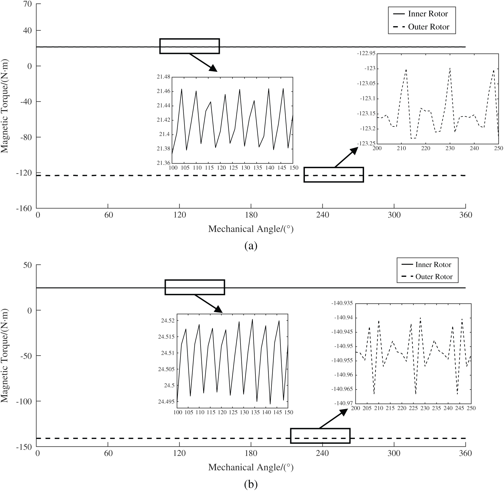
Figure 9: Dynamic torque (a) Conventional dynamic torque analysis. (b) Proposed dynamic torque analysis
Table 3: Average torque and torque ripple amplitude
In this paper, a scheme for replacing mechanical gearboxes with magnetic gears is proposed for the transmission system of Semi-Direct Drive Wind Turbines, and structural analysis and finite element performance analysis of this Halbach coaxial magnetic gear is performed. In terms of mechanical construction, magnetic gears offer the advantages of no contact, low noise, no frictional vibration, no lubrication and no overload protection. These properties can overcome the structural shortcomings of mechanical gearboxes. The permanent magnet mounting structure of the Halbach array magnetization method has greatly improved the torque performance of this coaxial magnetic gear. The self-shielded nature of the Halbach arrays allows for a unilateral increase in magnetic induction strength, which reduces the amount of inner and outer rotor yokes and the size of the wind power turbine. In addition, the Halbach array magnetization method generates more harmonics useful for torque and suppresses interference harmonics. Performance analysis showed that the static torque of Halbach magnetic gears was increased by 60%, with less torque fluctuations. Halbach array magnetic gears can transmit more torque, improve the magnetic induction strength waveform of the inner and outer layers, greatly reduce the torque fluctuation, and improve the transmission stability of magnetic gears. Therefore, this Halbach magnetic gear overcomes the disadvantages of mechanical gears and improves electromagnetic performance. It can better replace the mechanical gearbox in the semi-direct-drive wind turbine.
Funding Statement: This research was supported by the National Natural Science Foundation of China (Grant No. 51765020), and the Natural Science Foundation of Jiangxi Province (Grant No. 20161BAB206153).
Conflicts of Interest: The authors declare that they have no conicts of interest to report regardingthe present study.
1. Porte-Agel, F., Bastankhah, M., Shamsoddin, S. (2020). Wind-turbine and wind-farm flows: A review. Boundary-Layer Meteorology, 174(1), 1–59. DOI 10.1007/s10546-019-00473-0. [Google Scholar] [CrossRef]
2. Xiao, Z., Cheng, Y., Xiang, Z., Wang, X. (2015). Dynamic simulation and scale model experimental analysis of planetary gears train of semi-direct drive wind turbine. IEEE International Conference on Information and Automationional Conference on Information and Automation. DOI 10.1109/ICInfA.2015.7279621. [Google Scholar] [CrossRef]
3. Xiao, Z., Huan, L. (2017). Dynamic analysis of planetary gears with gear crack of semi-direct drive wind turbine. In: 2017 International Conference on Applied System Innovation, Sapporo, Japan.
4. Ji, X., Liu, Z., Liu, W., Zhang, X. (2019). Collaborative control of integrated generation and storage for offshore wind turbines. 2019 IEEE Innovative Smart Grid Technologies—Asia (ISGT AsiaChengdu, China. [Google Scholar]
5. Chen, C., Shi, Q., Wang, G. Y., Ge, H. Y., He, Z. W. (2015). Dynamic simulation of meshing force in broken tooth involute gear meshing process based on ADAMS. 2015 34th Chinese Control Conference, Hangzhou,China. [Google Scholar]
6. Chang, H., Borghesani, P., Smith, W. A., Peng, Z. (2019). Application of surface replication combined with image analysis to investigate wear evolution on gear teeth—A case study. Wear, 430–431, 355–368. DOI 10.1016/j.wear.2019.05.024. [Google Scholar] [CrossRef]
7. Liu, H. L., Liu, H. J., Zhu, C. C., Tang, J. Y. (2020). Study on gear contact fatigue failure competition mechanism considering tooth wear evolution. Tribology International, 147. DOI 10.1016/j.triboint.2020.106277. [Google Scholar] [CrossRef]
8. Li, X., Li, J., Zhao, C., Qu, Y., He, D. (2019). Early gear pitting fault diagnosis based on bi-directional LSTM. 2019 Prognostics and System Health Management Conference (PHM-QingdaoQingdao, China. [Google Scholar]
9. Qu, Y., Zhang, H., Hong, L., Tan, Y., Zhou, Z. (2018). Dynamic modeling and fault feature analysis of pitted gear system. 2018 IEEE International Conference on Prognostics and Health Management, Seattle, WA, USA. [Google Scholar]
10. He, H., Liu, H., Zhu, C., Wei, P., Sun, Z. (2018). Study of rolling contact fatigue behavior of a wind turbine gear based on damage-coupled elastic-plastic model. International Journal of Mechanical Sciences, 141, 512–519. DOI 10.1016/j.ijmecsci.2018.03.044. [Google Scholar] [CrossRef]
11. Feng, W., Lv, J., Hua, L., Long, H., Wang, F. (2017). Effect of relief-hole diameter on die elastic deformation during cold precision forging of helical gears. Procedia Engineering, 207, 627–632. DOI 10.1016/j.proeng.2017.10.1032. [Google Scholar] [CrossRef]
12. Jiang, L., Xiang, D., Tan, Y. F., Nie, Y. H., Cao, H. J. et al. (2018). Analysis of wind turbine Gearbox’s environmental impact considering its reliability. Journal of Cleaner Production, 180, 846–857. DOI 10.1016/j.jclepro.2018.01.078. [Google Scholar] [CrossRef]
13. An, Z., Liu, B., Xu, J. (2013). Dynamic reliability analysis of wind power gearbox component. 2013 International Conference on Quality, Reliability, Risk, Maintenance, and Safety Engineering, Chengdu, China.
14. Liang, C., Wang, X., Dou, Z. (2017). Risk assessment and reliability analysis for wind turbine gearbox fault based on FFMECA. 2017 4th International Conference on Systems and Informatics, Hangzhou, China.
15. Wang, J., Yang, S., Liu, Y., Mo, R. (2019). Overview on main design theory and load sharing characteristics of planetary gear trains. Journal of East China Jiaotong University, 36, 111–118. [Google Scholar]
16. Tsurumoto, K. (1991). Generating mechanism of magnetic force in meshing area of magnetic gear using permanent magnet. IEEE Translation Journal on Magnetics in Japan, 6(6), 531–536. DOI 10.1109/TJMJ.1991.4565201. [Google Scholar] [CrossRef]
17. Atallah, K., Wang, J., Mezani, S., Howe, D. (2006). A novel high-performance linear magnetic gear. IEEJ Transactions on Industry Applications, 126(10), 1352–1356. DOI 10.1541/ieejias.126.1352. [Google Scholar] [CrossRef]
18. Rasmussen, P. O., Andersen, T. O., Jorgensen, F. T., Nielsen, O. (2005). Development of a high-performance magnetic gear. IEEE Transactions on Industry Applications, 41(3), 764–770. DOI 10.1109/TIA.2005.847319. [Google Scholar] [CrossRef]
19. Atallah, K., Calverley, S. D., Howe, D. (2004). Design, analysis and realisation of a high-performance magnetic gear. IEE Proceedings—Electric Power Applications, 151(2), 135–143. DOI 10.1049/ip-epa:20040224.
20. Uppalapati, K. K., Bird, J. Z. (2014). An iterative magnetomechanical deflection model for a magnetic gear. IEEE Transactions on Magnetics, 50(2), 245–248. DOI 10.1109/TMAG.2013.2283018. [Google Scholar] [CrossRef]
21. Chen, M., Chau, K. T., Li, W., Liu, C. (2014). Cost-effectiveness comparison of coaxial magnetic gears with different magnet materials. IEEE Transactions on Magnetics, 50(2), 821–824. DOI 10.1109/TMAG.2013.2281988. [Google Scholar] [CrossRef]
22. Zhang, X. X., Liu, X., Wang, C., Chen, Z. (2014). Analysis and design optimization of a coaxial surface-mounted permanent-magnet magnetic gear. Energies, 7(12), 8535–8553. DOI 10.3390/en7128535. [Google Scholar] [CrossRef]
23. Liu, X. H., Chau, K. T., Jiang, J. Z., Yu, C. (2009). Design and analysis of interior-magnet outer-rotor concentric magnetic gears. Journal of Applied Physics, 105(7), DOI 10.1063/1.3058619. [Google Scholar] [CrossRef]
24. Kim, S., Kim, C., Jung, S., Kim, Y. (2015). Optimal design of novel pole piece for power density improvement of magnetic gear using polynomial regression analysis. IEEE Transactions on Energy Conversion, 30(3), 1171–1179. DOI 10.1109/TEC.2015.2421355. [Google Scholar] [CrossRef]
25. Cansiz, A., Akyerden, E. (2019). The use of high temperature superconductor bulk in a co-axial magnetic gear. Cryogenics, 98. DOI 10.1016/j.cryogenics.2019.01.008. [Google Scholar] [CrossRef]
26. Gardner, M. C., Johnson, M., Toliyat, H. A. (2019). Analysis of high gear ratio capabilities for single-stage, series multistage, and compound differential coaxial magnetic gears. IEEE Transactions on Energy Conversion, 34, 665–672. DOI 10.1109/TEC.2018.2868730. [Google Scholar] [CrossRef]
27. Jing, L., Gong, J., Ben, T. (2020). Analytical method for magnetic field of eccentric magnetic harmonic gear. IEEE Access, 8, 34236–34245. DOI 10.1109/ACCESS.2020.2974777. [Google Scholar] [CrossRef]
 | This work is licensed under a Creative Commons Attribution 4.0 International License, which permits unrestricted use, distribution, and reproduction in any medium, provided the original work is properly cited. |