DOI:10.32604/EE.2021.014269
| Energy Engineering DOI:10.32604/EE.2021.014269 | |
| Article |
Model Predictive Yaw Control Using Fuzzy-Deduced Weighting Factor for Large-Scale Wind Turbines
1XEMC Wind power Co., Ltd., Xiangtan, 411100, China
2School of Automation, Central South University, Changsha, 410083, China
*Corresponding Authors: Lingxiang Huang. Email: huanglingxiang@xemc-wind.cn; Dongran Song. Email: songdongran@csu.edu.cn
Received: 09 October 2020; Accepted: 21 October 2020
Abstract: Yaw control system plays an important role in helping large-scale horizontal wind turbines capture the wind energy. To track the stochastic and fast-changing wind direction, the nacelle is rotated by the yaw control system. Therein, a difficulty consists in the variation speed of the wind direction much faster than the rotation speed of the nacelle. To deal with this difficulty, model predictive control has been recently proposed in the literature, in which the previewed wind direction is employed into the predictive model, and the estimated captured energy and yaw actuator usage are two contradictive objectives. Since the performance of the model predictive control strategy relies largely on the weighting factor that is designed to balance the two objectives, the weighting factor should be carefully selected. In this study, a fuzzy-deduced scheme is proposed to derive the weighting factor of the model predictive yaw control. For the proposed fuzzy-deduced strategy, the variation degree and the increment of the wind direction during the predictive horizon are used as the inputs, and the weighting factor is the output, which is dynamically adjusted. The proposed model predictive yaw control is demonstrated by some simulations using real wind data and its performance is compared with the conventional model predictive control with the fixed weighting factor. Comparison results confirm the outweighing performance of the proposed control strategy over the conventional one.
Keywords: Wind turbine; yaw control; weighting factor; fuzzy logic control
Since this new century, renewable energies have attracted great attention due to the global warming and the gradual depletion of fossil energy. Among various renewable energies, the wind energy has been globally utilized and rapidly developed for its environmental-friendly feature and low production cost. According to the global wind report 2019 [1], with installations of 60.4 GW, 2019 was the second largest year in history and close to the bumper year of 2015 (63.8 GW). The 60.4 GW of new installations brings global cumulative wind power capacity up to 651 GW. In the onshore market, 54.2 GW was installed, an increase of 17 percent compared to 2018. China and USA remained the world’s largest onshore market, together accounting for more than 60 percent of new onshore additions. However, the industry is still far from reaching the accelerated level of growth which we know we can deliver, and which is expected from us by international institutions, governments and the public.
To support the accelerated level of growth and compete with other types of energy resources, it is an urgent demand to further decrease the cost of energy through developing advanced technologies for wind turbines (WTs). Among various technologies, WT control technology could directly affect the active power output and component load of WTs, and it has been regarded as one of the key points of WTs research [2]. The existing WTs are mainly divided into horizontal-axis and vertical-axis [3]. For vertical-axis WTs, the structural design is simplified and the cost of operation and maintenance can be reduced, because of no yaw system needed to track the wind direction. But the vertical-axis WT has a low conversion efficiency, and thus it has a small market share. For horizontal-axis WTs, the blades are designed according to the experience taken from designing airfoil profile. For its high efficiency in capturing wind energy, the horizontal-axis WT has been rapidly developed and widely used in the world.
In terms of the actuator type, the control technology of horizontal-axis WT can be divided into three parts [4]: Pitch, generator torque, and yaw control. In the existing horizontal-axis WT control literature, the pitch control and the generator torque control account for more than 80% of them, for their quick response to the changing wind speed. The main objectives of these two parts include optimizing power output below rated wind speed, and reducing component loads above rated wind speed. The other control area belongs to the yaw control part, of which the control objective involves wind energy capture, reducing fatigue load, and removing the wake effect on neighboring WT [5]. By comparison, the yaw control only receives limited attention, while it fails to provide a satisfactory performance. From the results on the Horns Reef wind farm, it has been showed that the potential power loss due to the yaw error was 2.7% [6]. According to the recent survey, the failure rate of the yaw system was listed as the top three contributors of the system failure rates [7]. Obviously, the industrial demand asks for research efforts in the yaw control area.
Recently, the Light Detection and Ranging technology (LIDAR) has been mature and is able to acquire the wind information in front of the WT [8]. Meanwhile, the soft measurement-based methods can predict the wind information with a considerable preciseness [9]. Taking advantage of the previewed wind information, the predictive control methods that make control decisions in advance can be constructed and could be potentially applied in the field of wind energy. Owe to its capability of incorporating predictions of future wind information and modeling how the WT will respond to the wind force, model predictive control has been gradually popular for controlling the WTs [10,11]. Depending on the types of the model, the model predictive control can be categorized into linear, hybrid, and nonlinear types. Comparing with the other two types, the linear model predictive control has been widely used in controlling WTs for its less computation complexity [12]. Since the parameters of the WT model may be uncertain, robust model predictive control algorithms have been accordingly proposed for different robustness issues [13]. There have been a considerable number of scientific publications in studying the model predictive controls for the pitch and generator control systems, but the relevant research on the yaw control system is limited.
To date there have been only several researchers that studied the model predictive control for the yaw control system [14–19]. The model predictive control theory was introduced by Spencer et al. to control the yaw system [14]. Therein, the future wind direction with a preview time of 60s was used to build up the prediction model by assuming the yaw rate adjustable. Later, a similar prediction model was implemented and its control performance was evaluated by Hure et al. [15]. In their studies, the model predictive controllers were designed based on the continuous model predictive control theory, in which the optimal problem was solved using a complicated quadratic programming solver. Recently, a novel discrete model predictive control method was proposed for the yaw control system by Song et al. [16–19]. In their method, a finite control set was built for the permissible actions of the yaw actuators [17], and a multi-objective particle swarm optimization-based method was employed to investigate the potential performance of model predictive yaw control (MPYC) system [18]. In above studies, MPYC has shown its advantage in comparison with conventional control methods. Meanwhile, detailed investigations have been conducted among MPYCs with different weighting factors under various wind conditions [19]. When previous studies clearly demonstrated that the performance of the MPYC system was noticeably affected by the wind conditions, the issue about how to improve the MPYC system remains unsolved.
Since the control performance of a WT is simultaneously affected by the wind condition and the control parameters, one potential way for improving the control performance is to adapt the control parameters to the wind condition. For instance, the gains of the proportional-integral (PI) controller are generally scheduled according to the varying operating points determined by the wind speed [20]. As for the standard torque control, the adaptive torque gain or additional terms are widely used to improve the track of the optimal speed determined by the wind speed [21,22]. When considering the MPYC, there are two objectives, namely, the captured energy and the yaw actuator usage. In the quality function, the two objectives are combined by a weighting factor, which will impose a noticeable influence on the performance of the MPYC strategy. Motivated by these observations, a fuzzy-deduced strategy is proposed to derive the weighting factor of the MPYC in this study. Specifically, the weighting factor is set as the output of the deduced strategy, which is variable and adaptive corresponding to two inputs, namely, the variation degree and the increment of the wind direction during the predictive horizon. By doing so, the comprehensive performance of the MPYC could be enhanced.
The remaining sections are arranged as follows: material and method are elaborated in Section 2. Method validation and result analysis are described in Section 3. Finally, the conclusion is presented in Section 4.
The baseline MPYC was introduced in [19], which was based on the assumption that the precise prediction of wind direction can be provided by advanced measurement devices, such as LIDAR. On this basis, the fuzzy-deduced strategy is proposed to derive the weighting factor of the MPYC in this study.
In the baseline MPYC, there are two objectives, namely, minimizing the energy loss and the yaw actuator usage. To do that, the two objectives are integrated into the objective function by employing the weighting factor. Since the two objectives are related to the yaw error, the yaw error is selected and taken as the predictive variable, which is estimated by a predictive model. In the predictive model, the yaw rate sequence is the control input, and thus it will be predefined during the prediction horizon. Finally, the optimal algorithm is introduced to search out the yaw rate sequence.
2.1.1 Objective Function Using the Fixed Weighting Factor
The MPYC system is with two objectives: minimizing the energy loss due to the yaw error while having the acceptable yaw actuator usage. The yaw actuator usage is measured using the usage ratio, and the production reduction factor is used to derive the dimensionless factor of evaluating the power production performance. On this basis, the two objectives are combined by the weighting factor  . When considering a prediction horizon
  , the objective function is formulated as:

where  is the yaw error averaged at the
  control period, and
  denotes the rotary speed of the nacelle, which is normally called as the yaw rate and defined as:
where  denotes the yaw rate specified by
  .
.
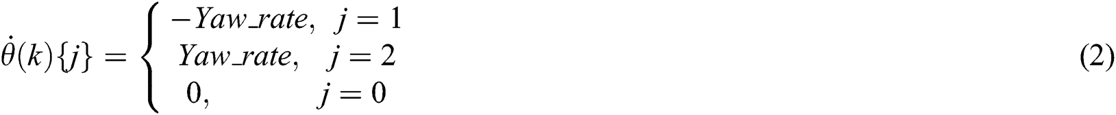
In Eq. (2), there are thee values the yaw rate can take. When the value of the yaw rate is unequal to zero, the yaw actuator usage will increase. Thus, the logic operator in Eq. (1) is expressed by:

2.1.2 Multiple-Step Predictive Model
In Eq. (1), it has been clear that the energy loss objective is related to the yaw error. Thus, the averaged yaw error  is selected as the state variable, of which the one-step prediction model is as follows:

where  ,
,  and
and  are the prediction values of the yaw error, wind direction, and nacelle position averaged at the next step, respectively.
The nacelle position  is estimated by:

where  is the step size of the controller.
With Eqs. (4) and (5), the  - step prediction model of the yaw error
  is obtained as:

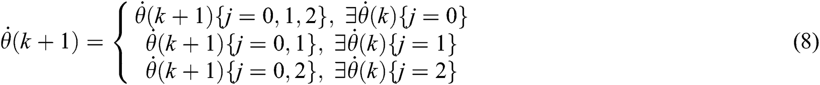
From Eq. (6), it is seen that the yaw error in the future relies on the coming yaw rate. Considering the prediction horizon  , the yaw rate sequence of the yaw system can be represented by:

In Eq. (7), there is a hardware constraint imposed on the yaw rate between neighboring control steps, formulated by:
With Eqs. (1) and (6)–(8), the optimization problem for the MPYC yaw system has been formulated, which is a nonlinear optimization issue under constraints. To facilitate solving the problem, the sampling and control periods are set same as the prediction step, and the control horizon is select to be equal to the prediction horizon. On this basis, the designed optimal problem can be effectively solved by using the exhaustive search (ES) method that is illustrated in a form of sequential diagram drawn in Fig. 1. The intelligent optimization algorithms, such as Particle swarm optimization, may be also used to solve the formulated optimization problem. In this application, the proposed ES method is recommended for its simple implementation and no heavy computation burden while finding the global optimal solution. For details about the ES method, the readers can refer to literature [19].
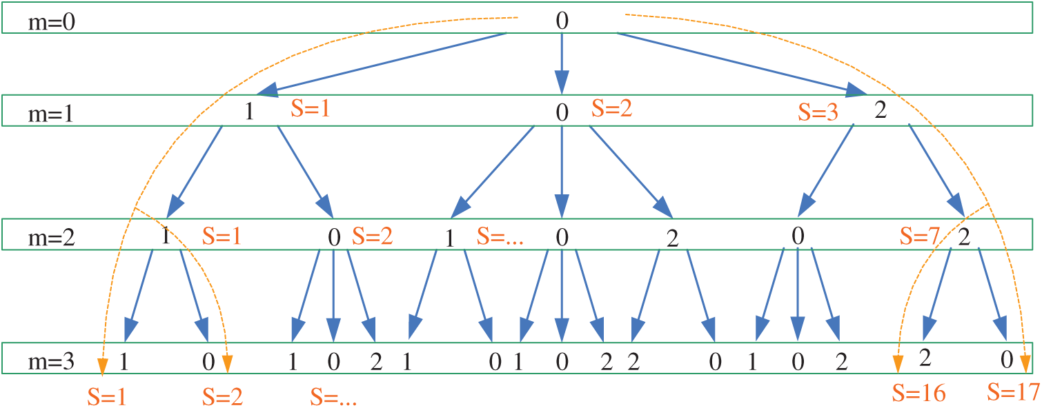
Figure 1: Sequential diagram of the ES method for a three-step prediction model
2.2 Fuzzy-Deduced Weighting Factor
When more than one control objectives are considered, the weighting factors must be appropriately tuned to obtain the satisfactory performance. Due to the lack of the systematic design method, the determination of the weighting factor is still an open research topic in general for the model predictive control area. In the literature, there are a great number of works considering the determination of weighting factors [23–25]. However, online dynamic adjustment for the weighting factors using fuzzy logic control technique has not been reported in the MPYC system. In this section, the fuzzy logic control technique is presented to dynamically choose the weighting factor.
2.2.1 Proposed Scheme of the Fuzzy-Deduced Weighting Factor
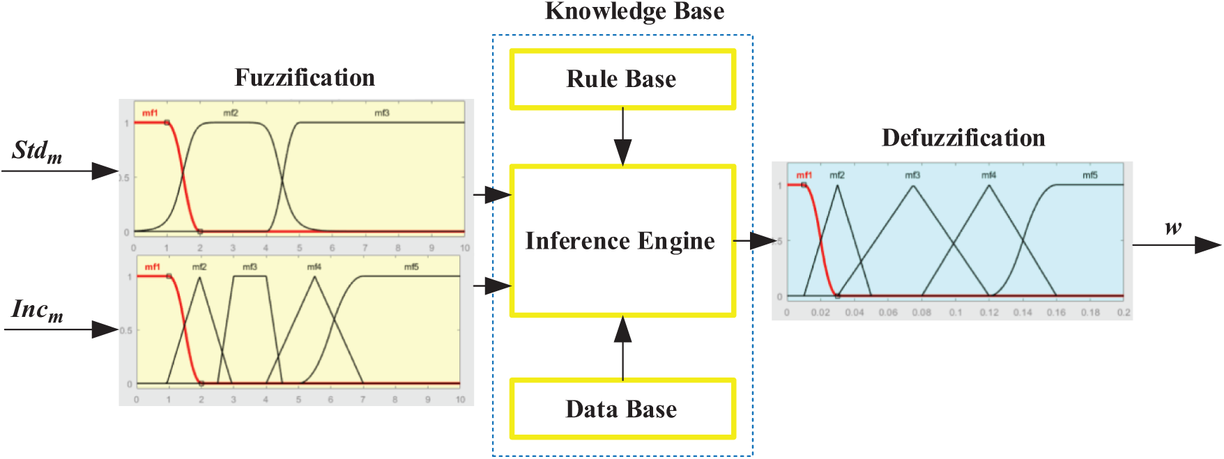
Figure 2: Scheme of the Fuzzy deduced weighting factor
Fig. 2 shows the proposed scheme of the Fuzzy deduced weighting factor. As shown in Fig. 2, the output variable is the weighting factor of the objective function, and the variation degree  and the increment
  of the wind direction during the predictive horizon are used as the input variables, which are calculated by:

where  denotes the mean value of the prediction wind direction during the prediction horizon. And,

where  denotes the absolute value.
In the fuzzy logic control technique, the Mamdani-type minimum inferential method cooperating with the center-of-area defuzzification procedure is utilized to produce the crisp evaluator output. The center-of-area defuzzification calculates the center of gravity of the reasoned results to obtain the crisp output and the calculation is indicated by:

where  is the crisp output,
  is the inferential results of rule
  ,
,  is the corresponding output of rule
  ,
,  is the rule number.
2.2.2 Selection of Membership Functions
After determining the input variables and inferential method, the membership functions corresponding to the  ,
,  , and weighting factor are designed and illustrated in Figs. 3a–3c, respectively. Five types of curves are utilized to design these three membership functions. Specifically, asymmetrical polynomial, and generalized bell curves are presented in Fig. 3a; asymmetrical polynomial, trapezoidal, and triangular curves are presented in Fig. 3b; asymmetrical polynomial and triangular curves are presented in Fig. 3c. The universe of discourse in the membership functions of
  and
and  are defined on the domain [0 deg, 10 deg] and [0 deg, 10 deg], respectively; while the discourse universe of the output membership function is defined on the normalized domain [0,0.2]. In Fig. 3, the linguistic values VS, S, M, L, and VL represent very small, small, medium, large, and very large, respectively.
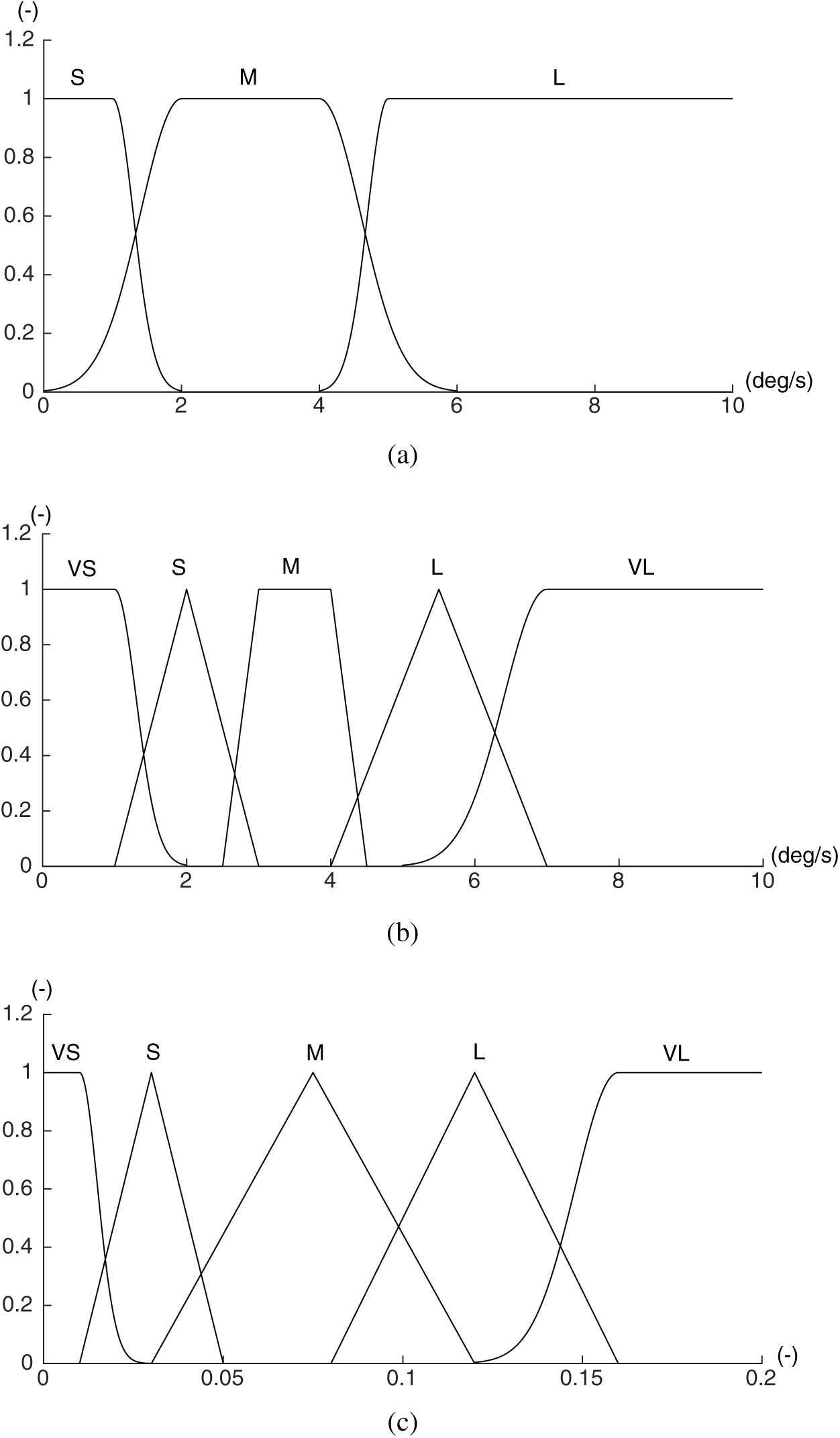
Figure 3: The membership functions of the input and output variables. (a) Membership function of input  , (b) Membership function of input
  and (c) Membership function of output
The scheme of the fuzzy-deduced weighting factor emulates the expert experience to achieve appropriate weighting dispatch, making it easy to incorporate heuristic rules that reflect specialist experience into the calculating processes. Consequently, the weighting distribution is driven by a set of control rules rather than a fixed value.
In Fig. 3, the input variable  is mapped into three different linguistic values, while the input variable
  is mapped into five different linguistic values. Thus, the proposed fuzzy rule table is composed of 15 different rules. The complete rule bases for the proposed module of the fuzzy-deduced weighting factor are illustrated in Tab. 1. As shown in Tab. 1, the dispatch rules are deduced to obtain the optimal value of the objective function based on the perception that the weighting factor is dynamically adjusted to fit the varying feature of the coming wind direction during the prediction horizon.
Table 1: Complete rule bases for the proposed strategy

3 Method Validation and Result Analysis
This section aims to demonstrate the capabilities of the proposed MPYC strategy using fuzzy-deduced weighting factor and to investigate its performance with different settings of the yaw control system. Therefore, the real wind direction data collected by the wind wanes mounted on the nacelle of an operating WT are used, of which the time series curve is drawn in Fig. 4.
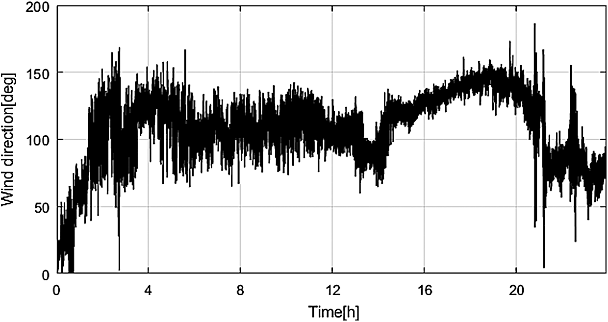
Figure 4: Scheme of the Fuzzy deduced weighting factor
The proposed MPYC strategy is validated by simulation tests, and compared with the baseline MPYC with the fixed weighting factor. Since the yaw rate plays a key role in the yaw control system, three simulation cases with different yaw rate are defined as follows:
• In simulation Case 1:  ,
,  ,
,  ;
;
• In simulation Case 2:  ,
,  ,
,  ;
;
• In simulation Case 3:  ,
,  ,
,  .
.
3.1 Results of Simulation Case 1
Fig. 5 shows the simulation results of Case 1 for the yaw system with the slowest yaw rate. As seen from Figs. 5a and 5b, the two MPYC controllers tracked the wind direction well, while there is slight difference between the yaw errors of the two controllers. Figs. 5c and 5d show that the proposed MPYC has less energy loss while taking less yaw actuator usage than the baseline MPYC. Fig. 5e shows the weighting factor of the proposed MPYC, which varies in a range of 0–0.2 and confirms the activation of the fuzzy-deduced strategy.
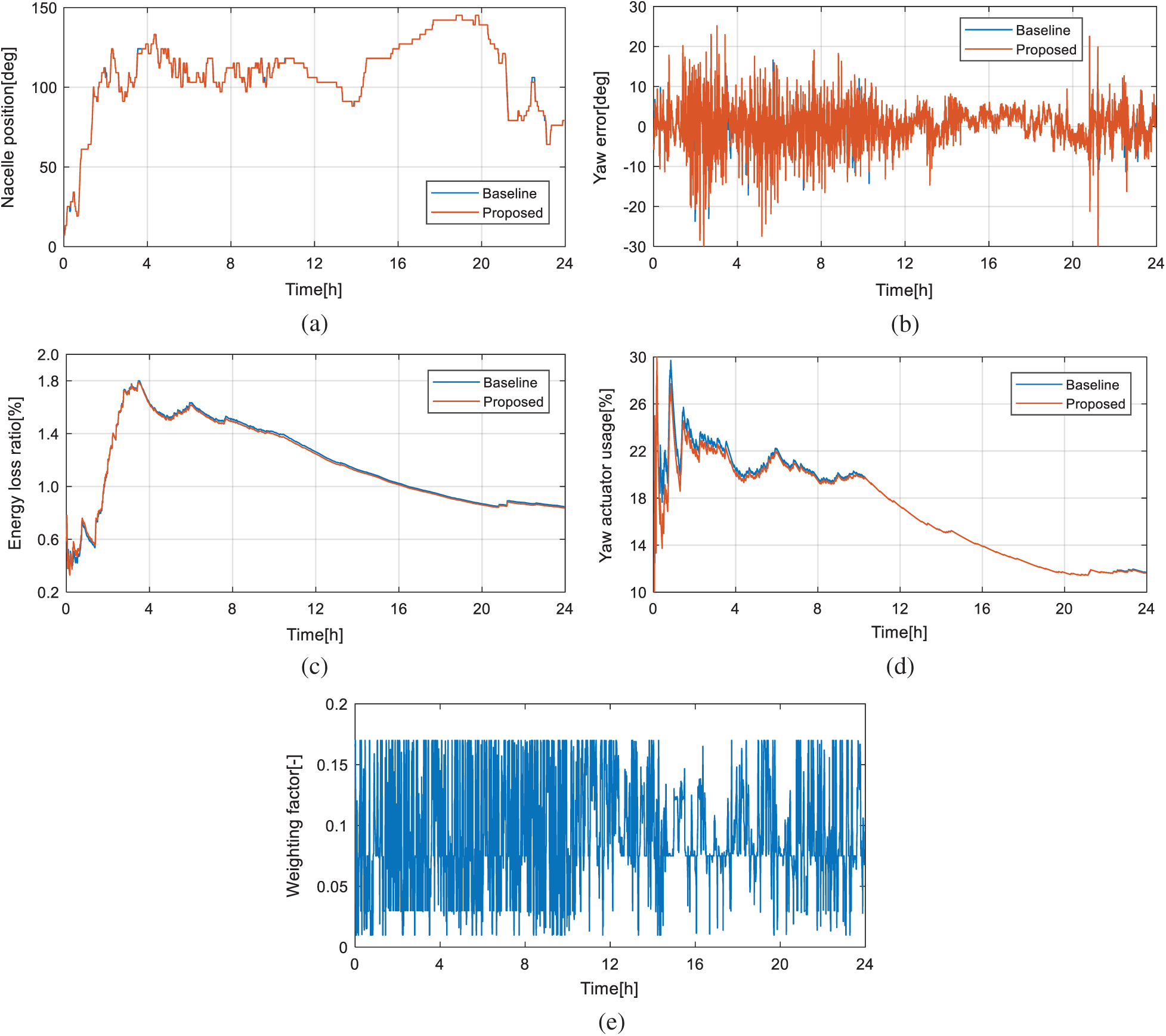
Figure 5: Results of simulation Case 1. (a) Nacelle position, (b) Yaw error, (c) Energy loss ratio and (d) Yaw actuator usage and (e) Dynamic weighting factor
3.2 Results of Simulation Case 2
In Case 2 for the yaw system with the medium yaw rate, the simulation results are shown in Fig. 6. Compared with the results in Case 1, a similar trend has been observed, that is, the two MPYC controllers succeeded in tracking the wind direction. By comparison to the baseline MPYC, the proposed MPYC takes less yaw actuator usage while capturing similar energy. Nevertheless, obvious differences are shown in case 2, that is, both of the yaw actuator usage and the energy loss become less. Therefore, these results verify the effectiveness of the proposed MPYC using the dynamic weighting factor.
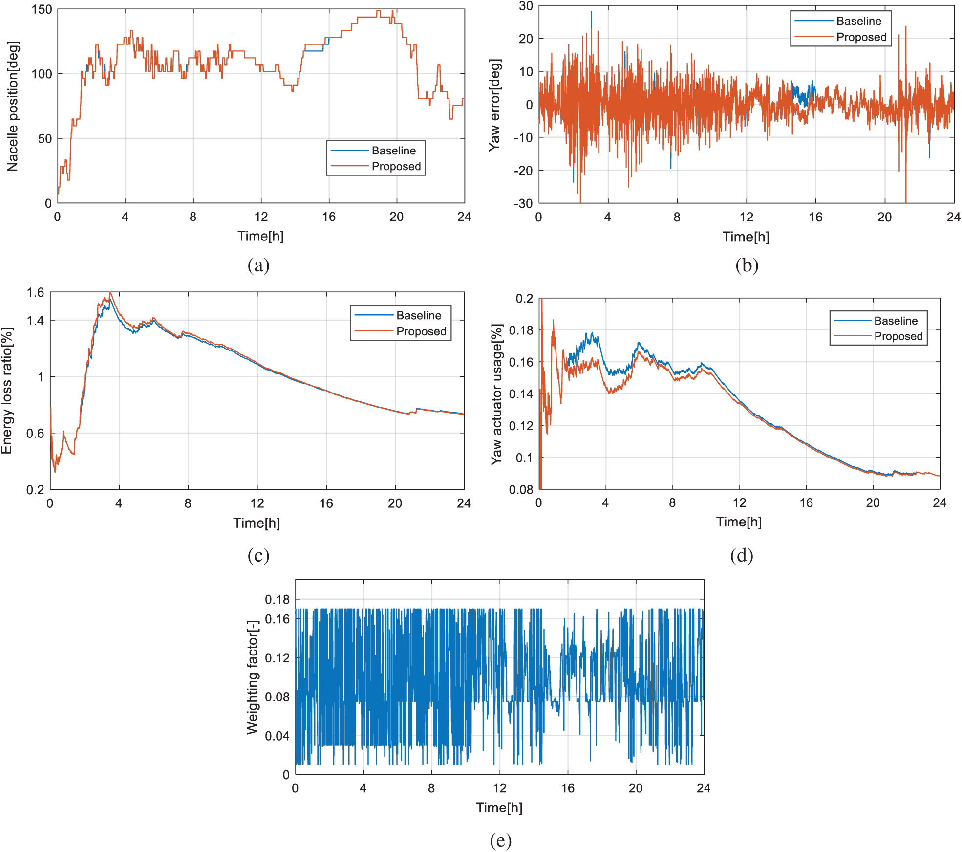
Figure 6: Results of simulation Case 2. (a) Nacelle position, (b) Yaw error, (c) Energy loss ratio and (d) Yaw actuator usage and (e) Dynamic weighting factor
3.3 Results of Simulation Case 3
Fig. 7 shows the simulation results of Case 3. Compared with the former two cases, the actuator usage and the energy loss are further decreased, respectively. Again, it is obvious that the proposed MPYC using dynamic weighting factor outweighs the baseline MPYC in terms of the performance of the actuator usage and the energy loss.
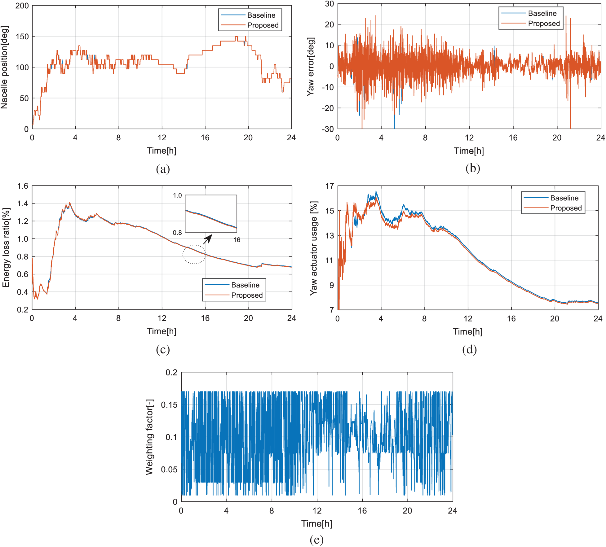
Figure 7: Results of simulation Case 3. (a) Nacelle position, (b) Yaw error, (c) Energy loss ratio and (d) Yaw actuator usage and (e) Dynamic weighting factor
3.4 Numerical Results and Analysis
To further compare the results, the average actuator usage, energy loss and values of objective function in the three cases are calculated. Under the three cases, the results are drawn in Bar plot, which are shown in Fig. 8. Meanwhile, the numerical results are summarized in Tabs. 2–3, corresponding to the results of the baseline MPYC and proposed MPYC, respectively.
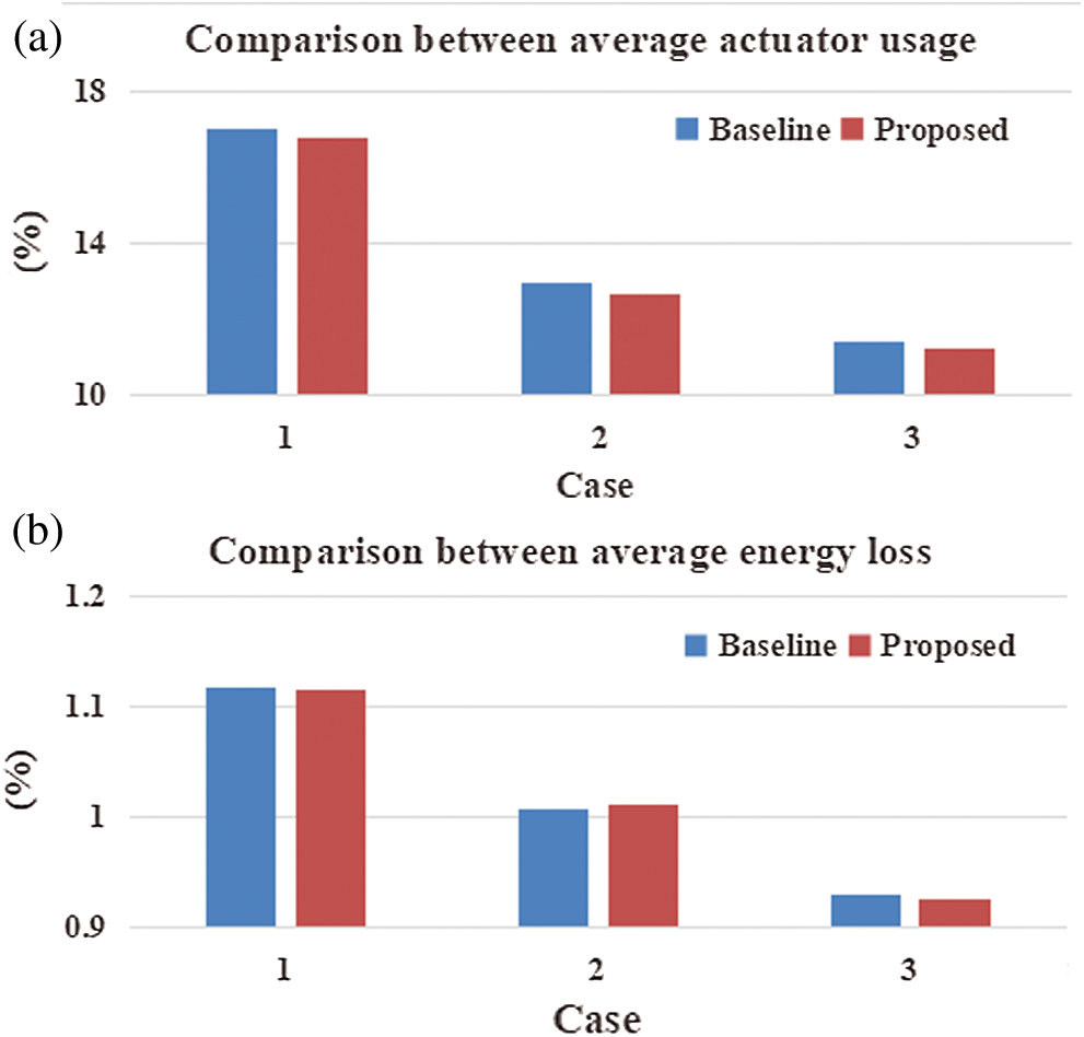
Figure 8: Result comparison between the baseline and proposed MPYC. (a) Average actuator usage of baseline MPYC and (b) Average energy loss of proposed MPYC
Table 2: Numerical results of the baseline MPYC

Table 3: Numerical results of the proposed MPYC using dynamic weighting factor

From Tabs. 2 and 3, it is shown that the average actuator usage of the yaw system with the baseline MPYC is 17.01%, 12.96%, and 11.40%, while the average energy loss is 1.117%, 1.007%, and 0.929%, for Cases 1, 2, and 3, respectively. By comparison, the average actuator usage of the yaw system with the proposed MPYC is 16.76%, 12.64%, and 11.25%, while the average energy loss is 1.116%, 1.012%, and 0.926%, for Cases 1, 2, and 3, respectively.
Thus, it is shown that, on one hand, the overall performance of the MPYC is enhanced when the yaw rate is increasing. The reason is that a larger yaw rate is beneficial to tracking the fast-varying wind direction for the yaw control system. On the other hand, the performance of the yaw system is enhanced by the proposed MPYC using dynamic weighting factor. Especially, the proposed MPYC reduces the average actuator usage by 0.25%, 0.32%, and 0.15% for the three cases, in comparison with the baseline controller.
These results show that the MPYC using the dynamic weighting factor has better comprehensive performance than the baseline MPYC using the fixed one under different yaw rate.
This paper has proposed an adaptive model predictive control method using the dynamic weighting factor for the yaw system of the horizontal variable-speed wind turbines, in which the weighting factor is dynamically adjusted by the fuzzy-deduced strategy. Since the performance of model predictive yaw control is influenced by the coming wind direction, the variation degree and the increment of the wind direction during the predictive horizon have been utilized as two inputs of the fuzzy-deduced strategy. In this way, the weighting factor is varying and driven by the two inputs and the fuzzy-deduced strategy. Through some simulations using real wind data, it has been shown that the proposed method has improved the overall performance of the predictive control-based yaw system under different yaw rate. In the future study, the proposed method could be potentially applied to the model predictive controls for the pitch control and torque control systems of the wind turbines.
Funding Statement: This work is supported by the National Natural Science Foundation of China under Grant 61803393, project supported by the Natural Science Foundation of Hunan Province (No. 2020JJ4751), and the Innovation-Driven Project of Central South University (No. 2020CX031).
Conflicts of Interest: The authors declare that they have no conflicts of interest to report regarding the present study.
1. Global Wind Energy Council. (2020). Global wind report 2019. https://gwec.net/global-wind-report-2019/. [Google Scholar]
2. Shafiqur, R., Umar, T. S., Luai, M. A. (2020). Wind farm-battery energy storage assessment in grid-connected microgrids. Energy Engineering, 117(6), 294–309. [Google Scholar]
3. Haytham, A., Ehab, H. B. (2020). Performance and cost analysis of energy production from offshore wind turbines. Energy Engineering, 117(1), 41–47. DOI 10.32604/EE.2020.010412. [Google Scholar] [CrossRef]
4. Suvash, C. S., Ali, M. S., Atta, S. (2020). Experimental study on modal and harmonic analysis of small wind turbine blades using NACA 63-415 aerofoil cross-section. Energy Engineering, 117(2), 1–17. DOI 10.32604/EE.2020.010418. [Google Scholar] [CrossRef]
5. Yang, J., Fang, L. Q., Song, D. R., Su, M., Yang, X. B. et al. (2020). Review of control strategy of large horizontal-axis wind turbines yaw system. Wind Energy, 233(8), 1. DOI 10.1002/we.2564. [Google Scholar] [CrossRef]
6. Pedersen, T. F., Gottschall, J., Kristoffersen, J. R., Dahlberg, J. A. (2011). Yawing and performance of an offshore wind farm. Brussels, EWEA Annual Event, pp. 13–19. [Google Scholar]
7. Pérez, J. M. P., Márquez, F. P. G., Tobias, A., Papaelias, M. (2013). Wind turbine reliability analysis. Renewable and Sustainable Energy Reviews, 23, 463–472. DOI 10.1016/j.rser.2013.03.018. [Google Scholar] [CrossRef]
8. Fleming, P. A., Scholbrock, A. K., Jehu, A., Davoust, S., Osler, E. et al. (2014). Field-test results using a nacelle-mounted lidar for improving wind turbine power capture by reducing yaw misalignment. Journal of Physics: Conference Series, 524(1), 012002. DOI 10.1088/1742-6596/524/1/012002. [Google Scholar] [CrossRef]
9. Ouyang, T., Kusiak, A., He, Y. (2017). Predictive model of yaw error in a wind turbine. Energy, 123, 119–130. DOI 10.1016/j.energy.2017.01.150. [Google Scholar] [CrossRef]
10. Schlipf, D., Grau, P., Raach, S., Duraiski, R., Trierweiler, J. et al. (2014). Comparison of linear and nonlinear model predictive control of wind turbines using LIDAR. 2014 American Control Conference. USA, 3742–3747. [Google Scholar]
11. Song, D. R., Yang, J., Dong, M., Joo, Y. H. (2017). Model predictive control with finite control set for variable-speed wind turbines. Energy, 126, 564–572. DOI 10.1016/j.energy.2017.02.149. [Google Scholar] [CrossRef]
12. Henriksen, L. C. (2010). Model predictive control of wind turbines (Ph.D. Thesis). Department of Information and Mathematical Model. Technical University, Denmark. [Google Scholar]
13. Mirzaei, M., Poulsen, N. K., Niemann, H. H. (2012). Robust model predictive control of a nonlinear system with known scheduling variable and uncertain gain. IFAC Proceedings, 45(13), 616–621. DOI 10.3182/20120620-3-DK-2025.00107. [Google Scholar] [CrossRef]
14. Spencer, M. D., Stol, K. A., Unsworth, C. P., Cater, J. E., Norris, S. E. (2013). Model predictive control of a wind turbine using short-term wind field predictions. Wind Energy, 16(3), 417–434. DOI 10.1002/we.1501. [Google Scholar] [CrossRef]
15. Hure, N., Turnar, R., Vasak, M., Bencic, G. (2015). Optimal wind turbine yaw control supported with very short-term wind predictions. 2015 IEEE International Conference on Industrial Technology. Spain, 385–391. [Google Scholar]
16. Song, D. R., Chang, Q., Zheng, S. Y., Yang, S. Yang, J. et al. (2020). Adaptive model predictive control for yaw system of variable-speed wind turbines. Journal of Modern Power Systems and Clean Energy, Early Access, 1, 1–4. DOI 10.35833/MPCE.2019.000467. [Google Scholar] [CrossRef]
17. Song, D. R., Yang, J., Fan, X. Y., Liu, Y., Liu, A. F. et al. (2018). Maximum power extraction for wind turbines through a novel yaw control solution using predicted wind directions. Energy Conversion and Management, 157, 587–599. DOI 10.1016/j.enconman.2017.12.019. [Google Scholar] [CrossRef]
18. Song, D. R., Fan, X. Y., Yang, J., Liu, A. F., Chen, S. F. et al. (2018). Power extraction efficiency optimization of horizontal-axis wind turbines through optimizing control parameters of yaw control systems using an intelligent method. Applied Energy, 224, 267–279. DOI 10.1016/j.apenergy.2018.04.114. [Google Scholar] [CrossRef]
19. Song, D. R., Li, Q. A., Cai, Z. L., Li, L. Yang, J. et al. (2019). Model predictive control using multi-step prediction model for electrical yaw system of horizontal-axis wind turbines. IEEE Transactions on Sustainable Energy, 10(4), 2084–2093. [Google Scholar]
20. Tang, X. S., Yin, M. H., Shen, C., Xu, Y., Dong, Y. Z. et al. (2019). Active power control of wind turbine generators via coordinated rotor speed and pitch angle regulation. IEEE Transactions on Sustainable Energy, 10(2), 822–832. DOI 10.1109/TSTE.2018.2848923. [Google Scholar] [CrossRef]
21. Chen, Z. Y., Yin, M. H., Zou, Y., Meng, K., Dong, Z. Y. (2017). Maximum wind energy extraction for variable speed wind turbines with slow dynamic behavior. IEEE Transactions on Power Systems, 32(4), 3321–3322. DOI 10.1109/TPWRS.2016.2623981. [Google Scholar] [CrossRef]
22. Li, W. J., Yin, M. H., Chen, Z. Y., Zou, Y. (2017). Inertia compensation scheme for wind turbine simulator based on deviation mitigation. Journal of Modern Power Systems and Clean Energy, 5(2), 228–238. DOI 10.1007/s40565-016-0202-y. [Google Scholar] [CrossRef]
23. Kuo, C. H., Kuo, Y. C., Chou, H. C., Lin, Y. T. (2017). P300-based brain–computer interface with latency estimation using ABC-based Interval type-2 fuzzy logic system. International Journal of Fuzzy Systems, 19(2), 529–541. DOI 10.1007/s40815-016-0205-x. [Google Scholar] [CrossRef]
24. Xing, L., Wang, D., Peng, Z. H. (2018). Cascade-free fuzzy finite-control-set model predictive control for nested neutral point-clamped converters with low switching frequency. IEEE Transactions on Control Systems Technology, 27(5), 2237–2244.
25. Wang, S. C., Liu, Y. H. (2014). A PSO-based fuzzy-controlled searching for the optimal charge pattern of Li-ion batteries. IEEE Transactions on Industrial Electronics, 62(5), 2983–2993. DOI 10.1109/TIE.2014.2363049. [Google Scholar] [CrossRef]
 | This work is licensed under a Creative Commons Attribution 4.0 International License, which permits unrestricted use, distribution, and reproduction in any medium, provided the original work is properly cited. |