DOI: 10.32604/EE.2021.012647
ARTICLE
Experimental Research of the Radiator Thermal Performance Test Equipment and Its Application in Heating System
1Basic Experimental and Training Center, Tianjin Sino-German University of Applied Sciences, Tianjin, 300350, China
2College of Mechanical Engineering, Tianjin University of Science and Technology, Tianjin, 300222, China
3Tianjin Qicheng Science and Technology Co., Ltd., Tianjin, 300193, China
4Software and Communication School, Tianjin Sino-German University of Applied Sciences, Tianjin, 300350, China
5School of Energy Engineering, Tianjin Sino-German University of Applied Sciences, Tianjin, 300350, China
*Corresponding Author: Lian Zhang. Email: zhanglian@tsguas.edu.cn
Received: 07 July 2020; Accepted: 31 October 2020
Abstract: Radiator thermal performance test equipment plays a key role in the processing of developing a new type of heat radiator and its application products. The precise of temperature controlling, temperature measuring and flow measuring are the vital factors for a radiator thermal performance test equipment. Based on the above background, this paper improves the measurement and control system of radiator thermal performance test equipment, which improves the accuracy of the radiator thermal performance test equipment. This paper also optimizes the software and hardware system simultaneously so as to improve the precision of the auto-test system of test equipment. The flow rate ranges from 175 kg/h to 178 kg/h under different conditions. The average is 176.5 kg/h and the deviation rates are from 1.62% to 1.97%. The heat produced under various conditions is different. The maximum is 4.3 kW and the minimum is 4.2 kW for condition 1, the maximum is 3.3 kW and the minimum is 3.2 kW for condition 2 and the maximum is 1.95 kW and the minimum is 1.89 kW for condition 3. However, the deviation rate is about 2.9%, which shows that the device has high stability and high precision. This paper studies a new electronic heat cost allocate meter test method by radiator thermal performance test equipment at the same time. This paper tests temperature changes through four measures points and gets a result appeared as a heat backup which should be avoided when using in the test of electronic heat cost allocate meter. Some experiences and references could be gained for further research in the heating system from this test and research.
Keywords: Electronic heat cost allocate meter; radiator; precise control; heating
In the process of the research of the radiator, radiator thermal performance test equipment plays a key role in it. In the HVAC system design, the basis of the design is making a clear understanding about thermal characteristics of the chosen radiator and its heating capacity under any work condition. So, the research of every new radiator must be tested in this equipment to get its thermal characteristics. Otherwise, with the development of some new technique such as the heat supply of measurement, some new products which have relationship with radiator (for example: Heat cost allocate) come into the market. The performance must be tested in the radiator thermal performance test equipment. From this point of view, the radiator thermal performance test equipment plays a key role in the test of the radiator and some new products which have relationship with radiator, it also promotes the research and manufacture for new products.
Some companies such as HONEYWELL and DANFOSS which relate to the HVAC product also have their own test equipment. Recently, some famous universities have built some radiator thermal performance test equipment that have made contributions for the research and design of the new products.
The accurate of thermal energy and reasonable charge has been focus in our society. On the basis of thermal measurement, the thermal energy meter has been installed which could test energy variation by fluid in a heat loop. This technology is from Europe. Especially undergo the crisis of the energy in 1970s, how to save the limited energy with the development of economic has been a research problem in each country. Every commercial and industrial building consume huge energy in heating, especially in cold countries of the north Europe because the great temperature difference between outdoor and indoor as well as the longer heating period. From the survey and theory analyze, it is passive for saving energy from enhancing the building’s own insulation performance and its saving potential is limited too. In the early 80s, the heating charge system has a prevalence trend in Europe and USA, the charge method has been improved step by step and the technology of thermal energy measurement has already been matured. There are three types of meter used in Europe which are heat cost allocators based on the evaporation principle, heat cost allocators with electrical energy supply and exact heat meter. A survey shows that the central heating uses the household measurement could save about 10%–20% energy in developed country. On the basis of energy supply status and people’s charge ability, researchers should start an innovation in heating system and its products.
Matjaž et al. [1] presented an experimental study to verify an enhanced heat output regulation concept for the multi-panel radiators. Witry et al. [2] got the CFD results for a patterned plate heat exchanger by using the CFD which show enormous levels of possible characteristics improvement on both sides of the heat exchanger. The influence of location and temperature gradient direction on the performance of thin planar radiator had been studies by AminHossein et al. [3]. Numerical study on the thermal performance of a circulating radiator with flow pulsation had been carried out by Embaye et al. [4]. A combined analysis model for improving the prediction accuracy of heat dissipation in a radiator heated room had been launched by Karl-Villem et al. [5]. Experimental analysis of the emission efficiency of the parallel series radiator in EN 442 test chamber had been studied by Karl-Villem et al. [6]. Rahmati et al. [7] had a study about the experiment and numerical analysis of the improved hot water radiator. Thermal radiator embedded in pulsating heat pipe: infrared thermal imaging and simulation had been proposed by Vadiraj et al. [8]. A thermal model of the energy loss through the wall behind the radiator had been established by Robinson et al. [9]. Thermal performance analysis of a new refrigerant heater and air source heat pump heating system had been carried out by Shao et al. [10]. Gheibi et al. [11] had an experimental and numerical study on the thermal performance of a new type of modified baseboard radiator.
In the thermal performances test of the radiator, some deviation must inevitably create in the test which mainly come from measurement process and data processing. For the correct result, the accurate of the temperature and flow rate must be improved by enhancing the accurate of the test and data collect. That is always a key role in the radiator thermal performance test equipment. For standard radiator thermal performance test equipment, its thermal performance of structure size and maintenance structure could easily satisfy the requirement and the key problem is the stable control of the indoor temperature and the accurate test of the temperature and flow rate. There is some radiator thermal performance equipment in the world now and most have own temperature control and test system. The temperature control adopts PID control and SCM (short for single chip microcomputer) to realize control function.
So, combined with the design, build and test of radiator thermal performance equipment, this paper mainly studies the hardware and software of test system in the radiator thermal performance test equipment system. The factors which affect the accurate of test result and a feasible method will be carried out in this experimental study. On the basis of radiator thermal performance equipment, the electronic heat cost allocate meter test method which is applied to energy system will be launched too.
The airtight indoor size of radiator thermal performance test chamber is (4 ± 0.2 m) × (4 ± 0.2 m) × (2.8 ± 0.2 m). There is an interlayer between indoor and outdoor. The cooling interlayer is circular air equipment and have a heating medium cycle which could ensure the surrounding environment is stable. The test meter and control equipment are arranged in the indoor and outdoor space.
Hot water cycle system is constituted by head water tank, lower water tank, cycle pump, radiator, the glass rotor flow meter, electromagnetic valve, electric control valve, electronic balance and so on. The cycle pump convey water from lower tank to head tank to keep the water level of head tank constant under the action of overfall baffle effect. To ensure the uniform water temperature in head tank, the system set up water ejector equipment at the supply place of the head tank. The hot water from head tank enters the radiator automatically to keep the water in radiator under constant pressure. The hot water has been used by radiator, then reset to lower tank through the floater meter and finish the water cycle. An electronic balance is set to test the water flow rate which go through the radiator. The water leaves the floater meter and across two electromagnetic valves, then arrive at the electronic balance for measuring or going to the lower tank at last.
The indoor temperature system is consisted of air conditioner unit, supply air diffuser, plenum chamber, return air grilles and air heater. The test indoor cooling system use air cooled mode. The air pass through the filter, surface air cooler, fan, supply blast pipe in the air conditioner unit and the air is heated by air heater then supply to the interlayer which from four supply air diffuse of the indoor roof to exchange the heating with the wall of the indoor space. The air returns to the air conditioner unit through the return air grilles at last. The air heater is applied to control and adjust the indoor temperature by combining the cooling system to realize the accurate control. It is difficult to reach the static target by only using the cooling system to control and adjust. So, this system uses air heater to achieve dual precision control because the accuracy of the system is the key factor for testing. It could reach the static condition rapidly and ensure homogeneous indoor temperature fields because the electric heating has smaller inertia and could be controlled easily.
The control equipment of the radiator thermal performance test equipment comprises the electronic control panel (control the head water tank, lower water tank and the indoor temperature) and temperature itinerant detecting control panel. The electric control valve, electromagnetic valve, electronic balance, the Pt resistance of the indoor point for measuring temperature are controlled by control panel.
(1) Electronic Control Panel
The supply, the return temperature of the radiator and indoor temperature should be controlled in the radiator thermal performance test. The whole system is homeostasis when the heating load of the radiator is equal to the cooling load of the cooling system and the indoor temperature is steady. The system uses computer control system on the basis of the required high precision of temperature. The electronic control panel chart is shown in Fig. 1.
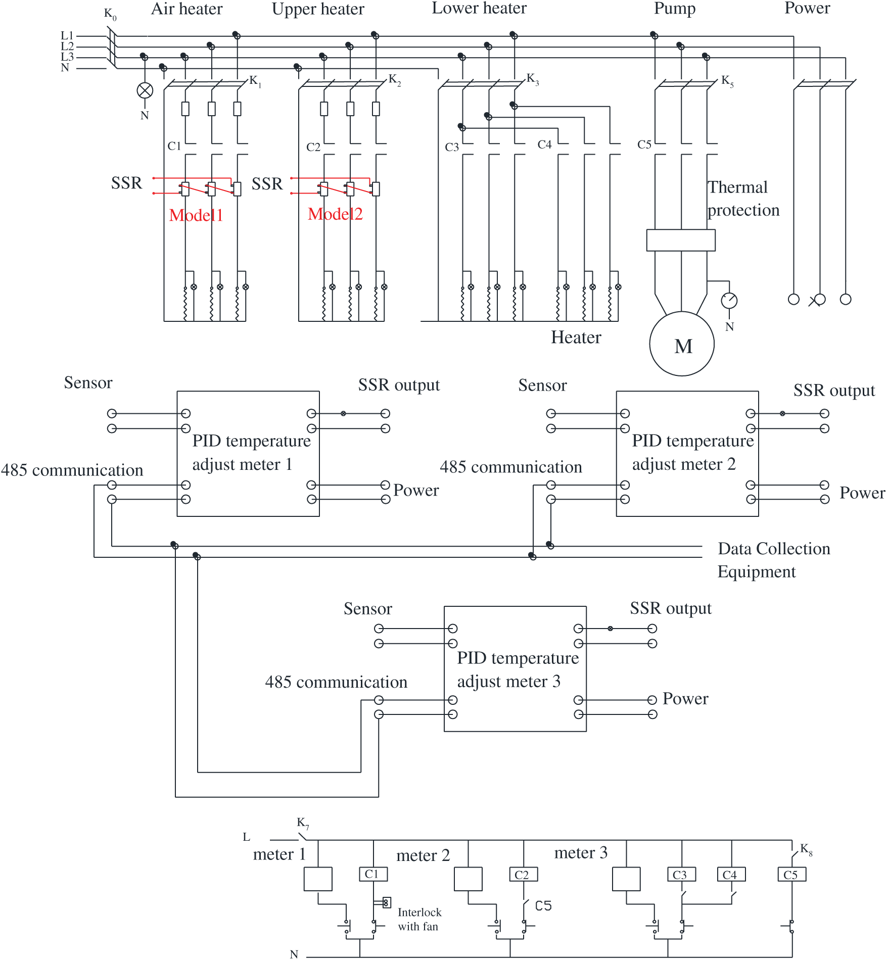
Figure 1: The principle chart of the electric control panel. The electric heater has a leakage protection
(2) Temperature Itinerant Detecting Control Panel
The radiator thermal performance test has two water temperature test points and twenty air temperature test points which have a high accuracy requirement. The air temperature of base point and supply and return temperature of the radiator must have a higher accuracy from –0.1°C to +0.1°C and other temperature of test points (the wall temperature and the air temperature except the base point) have a lower accuracy from –0.2°C to +0.2°C. Four water temperature test points has been added in the high temperature area and the accuracy is from –0.1°C to +0.1°C to realize a thermal performance test for the new electronic heat cost allocate meter. The temperature itinerant detecting system involve Pt1000 resistance, control panel, computer interface board and center computer. The principle chart is shown in Fig. 2.
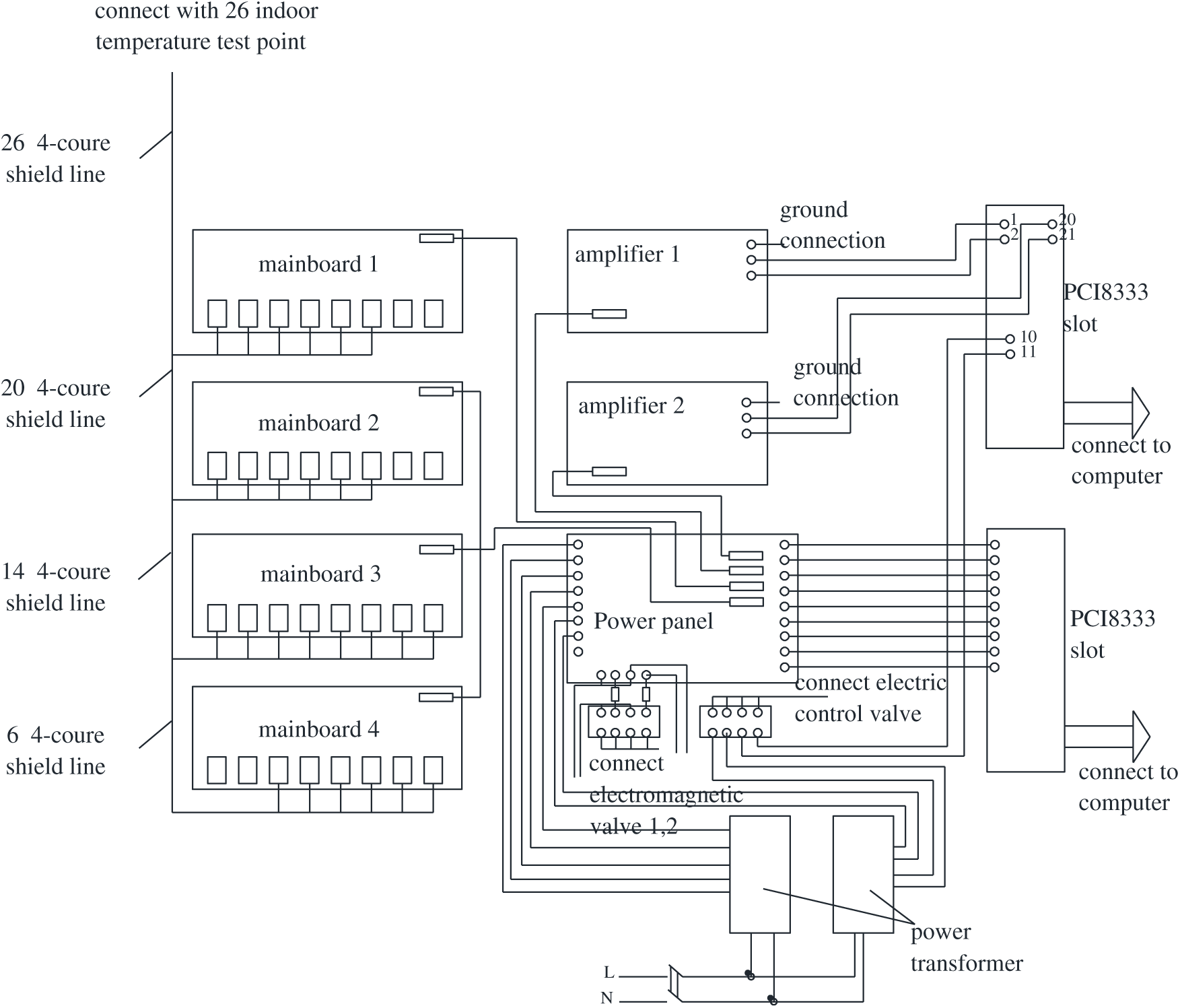
Figure 2: The principle chart of temperature itinerant detecting control panel
The radiator thermal performance test is a complicated process which has 26 temperature point measurements, steady condition judgment, flow rate collection and data processing. To finish all the function exactly and efficiently, the system uses the software to develop the main program such as the test of temperature and flow rate and data processing. This program could improve the speed and precision of the test. It also has a visual interface communicating with user to realize the data processing and finish whole auto test function. The main program is consisted of data processing, steady judgment, test, database management, history data inquiry, display, print, and help. The flow rate chart of software is shown in Fig. 3. Access database is applied to complete data saving, collating, refreshing, and inquiring. Considering the independence and integrality of every test data, the database could save every data immediately.
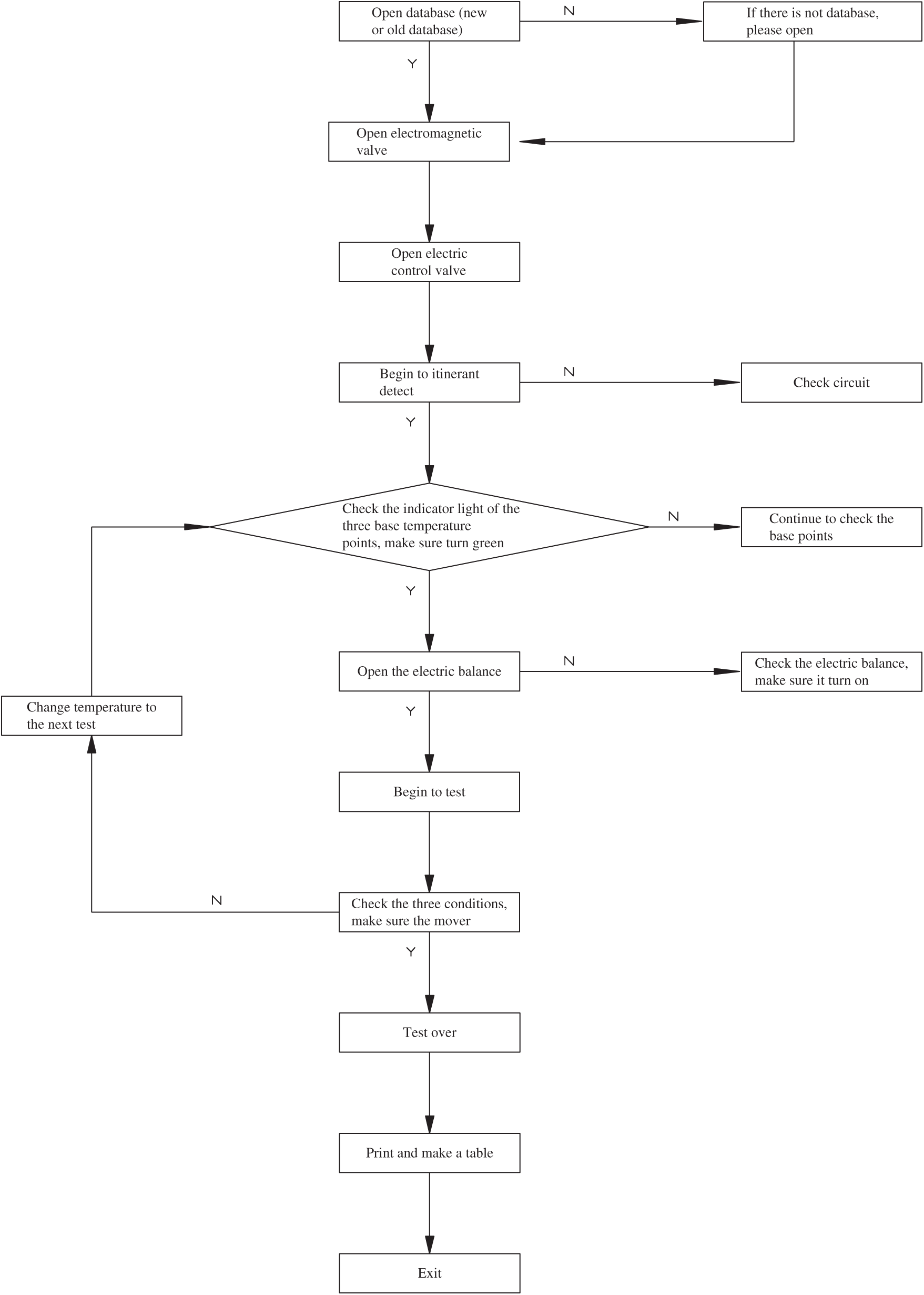
Figure 3: The software chart
3 The Radiator Thermal Performance Test
Some radiator thermal performance test has been conducted to verify the accurate of this proposed system. The theory and experiment setup will be stated, and the results and analysis of the experimental also be descripted in this part.
3.1.1 Calculation for the Heat Dissipation of the Radiator

where:
Q = heat dissipation of the radiator, W;
Gp = average flow rate of heating medium, kg/s;
h1 = supply enthalpy of radiator, J/kg;
h2 = return enthalpy of radiator, J/kg.
According to the temperature and pressure of heating medium from radiator, h1 and h2 could be got.
3.1.2 The Heat Dissipation of the Radiator
The heating medium is hot water in this experiment. Test the water temperature of radiator supply and return side, when the temperature of hot water is below the temperature of water boiling point at atmospheric pressure. For another way, the water temperature and the pressure of radiator supply and return side, should be tested.
The parameter of the heating medium must satisfy as follow which is refer to the Chinese standard (GB/T13754-92):
(1) Flow rate: ±0.5%;
(2) Temperature: ±0.1°C;
(3) Pressure: ±1%.
This experiment uses the 760-type radiator which satisfies Chinese standard (GB/T13754-92). The heat dissipation should higher than 700 W and not beyond 87 W per cubic meter. The radiator is parallel to one of walls and symmetric with the center. The nearest distance between radiator and its wall is 0.05 ± 0.005 m. The radiator should be installed horizontally and the distance between the bottom of the radiator and the floor is 0.12 m.
In the first three tests, the average hot water temperature of the radiator supply and return is 50 ± 5°C, 65 ± 5°C, 80 ± 3°C. Each test must under the same flow rate and the deviation of the flow rate is below ±2%. When the difference between the average water temperature of radiator supply and return and the base point air temperature is 60 ± 1°C, the temperature difference between supply and return is 20 ± 2°C.
Start continuous measurement at same time interval not beyond 10 min when the heating medium and the indoor air temperature reach the steady state under same conditions. The total time is more than 1 h; the data record includes the temperature, pressure, flow rate of the heating medium and indoor. The average value could be applied to calculate heat dissipation after validating the data deviation in the steady range.
From the Figs. 4–8, the results show that the supply water temperature is about 90°C, the return water temperature is about 70°C, the base point temperature is about 20°C in condition 1; the supply water temperature is about 75°C, the return water temperature is about 60°C, the base point temperature is about 20°C in condition 2; the supply water temperature is about 55°C, the return water temperature is about 45°C, the base point temperature is about 20°C in condition 3. Although the supply water temperature and return water temperature changed, the base point temperature is constant. The indoor temperature is steady and the environment in winter is comfortable. Fig. 7 shows the flow rate of different conditions has a smaller range from 175 kg/h to 178 kg/h. The average is 176.5 kg/h and the deviation rate are from 1.62% to 1.97% which means the flow rate is constant. The heating is different too. The maximum is 4.3 kW and the minimum is 4.2 kW in condition 1; the maximum is 3.3 kW and the minimum is 3.2 kW in condition 2; the maximum is 1.95 kW and the minimum is 1.89 kW in condition 3. But the deviation rate is about 2.9% in every condition. Therefore, this radiator thermal performance test equipment has good stability and high accuracy.
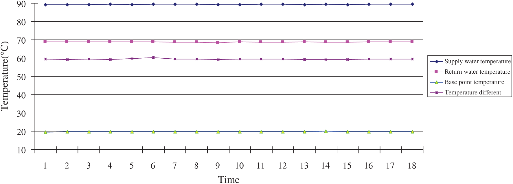
Figure 4: Three experiments in condition 1
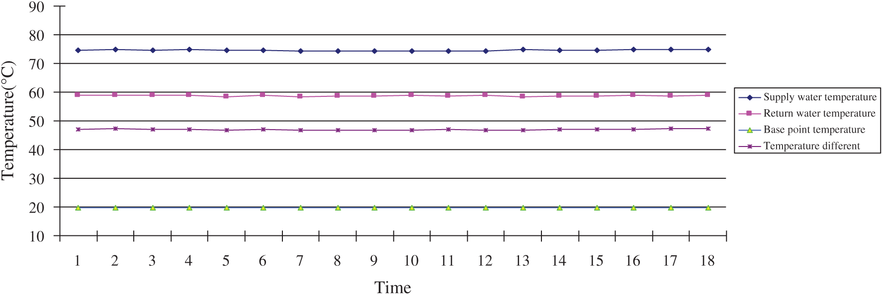
Figure 5: Three experiments in condition 2
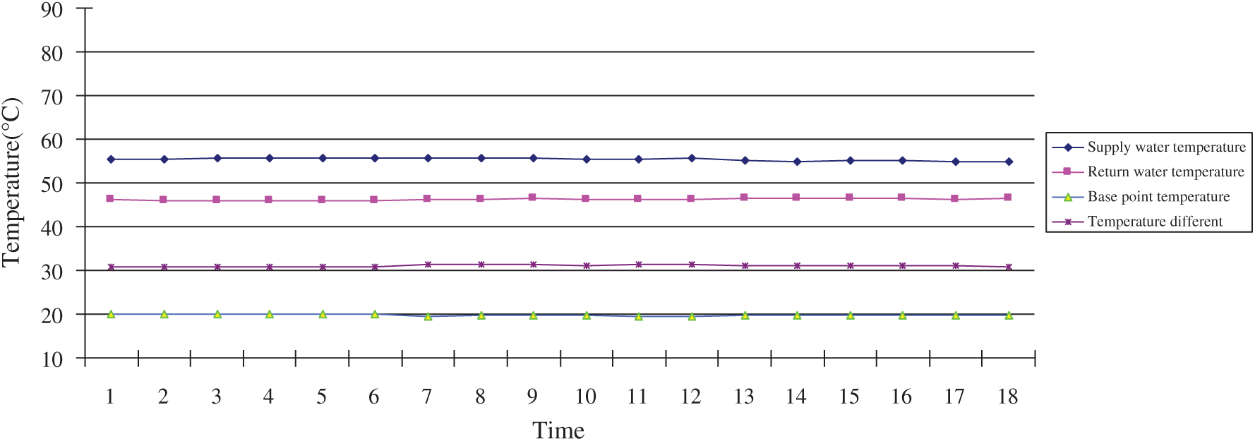
Figure 6: Three experiments in condition 3
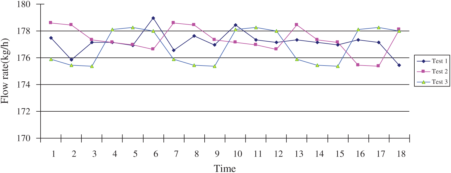
Figure 7: Flow rate of three experiments
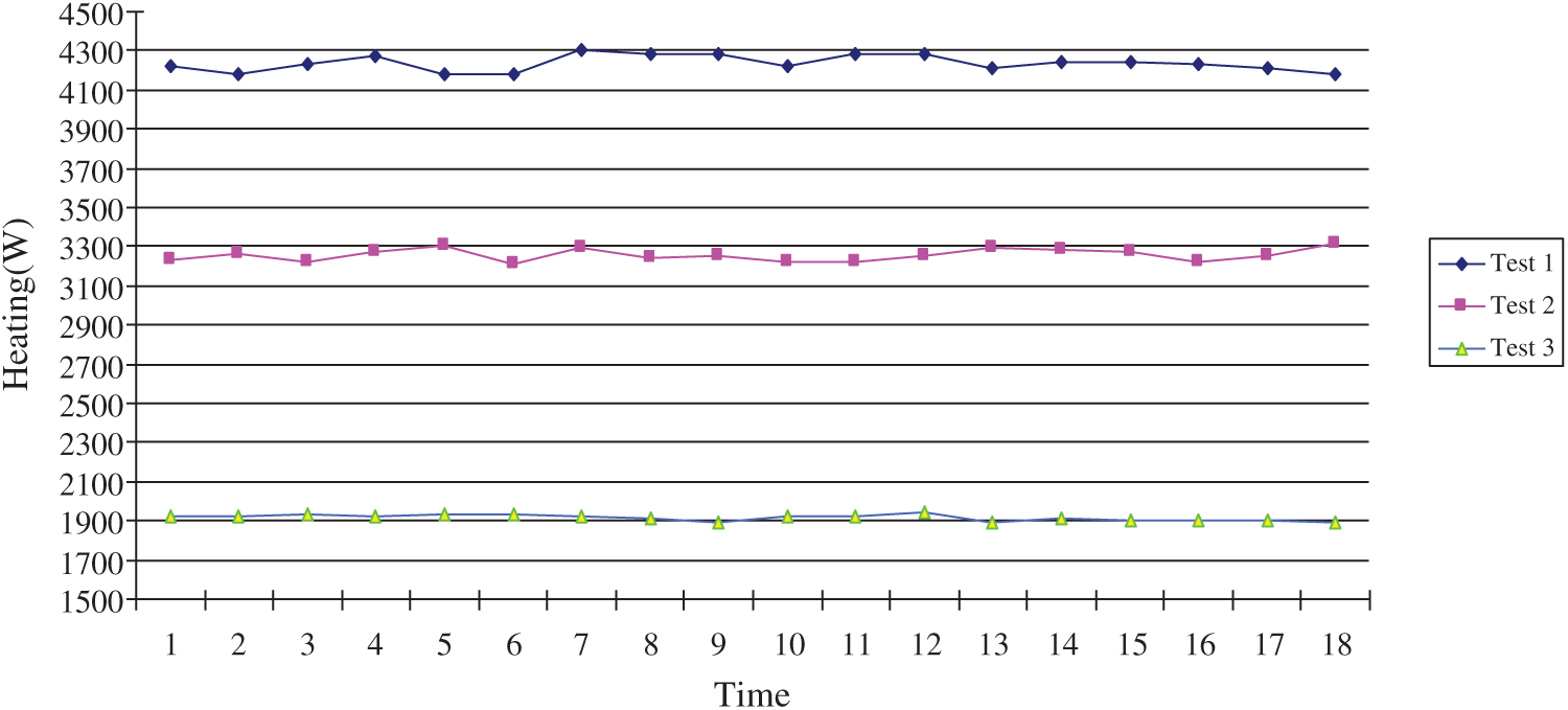
Figure 8: Heating of three experiments
4 Application of Radiator Thermal Performance Test Equipment in Energy System
The test equipment could test electronic heat cost allocate meter and heat cost allocators meter based on the evaporation principle in the energy system, but this paper only refers to the former.
The electronic heat cost allocate meter has three different types. The first one is single sensor and it uses only one temperature sensor to test average temperature of the radiator heating medium. The second one is double sensor which uses two temperature sensors to test average temperature of the radiator heating medium and indoor temperature respectively. The third one is triple sensor which use three temperature sensors to test supply and return water temperature of the radiator and indoor temperature. This paper studies the first and the second electronic heat cost allocate meter.
The radiator thermal performance test equipment is applied to test electronic heat cost allocate meter and find out the heat resistance problems which exist in the application course simultaneously.
The electronic heat cost allocate meter is an equipment which could test the radiator performance temperature and its heating time integration. The display value of single sensor is an approximation of the radiator performance temperature and its heating time integration. The display value of double sensor is an approximation of the difference between average temperature of radiator and indoor temperature and its heating time integration.
The electronic heat cost allocate meter value is affected by radiator, the modify coefficient of the radiator power, the modify coefficient of heating couple, the modify coefficient of indoor temperature, all modify coefficient of, installation manner and so on. This value is dimensionless. The test condition is as follows: heating medium temperature is 40°C–60°C; the base point temperature is 20 ± 2°C; the flow rate could be tested in condition 1 and the flow rate remains constant under different test conditions (from part 3).
Four typical temperature points of the electronic heat cost allocate meter is tested to form a temperature field. These 4 temperature points are shown in Fig. 9.
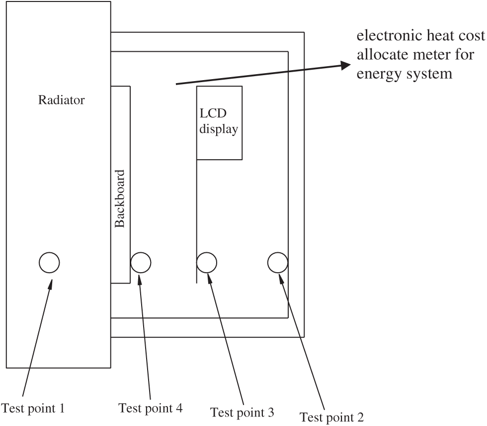
Figure 9: 4 test points chart
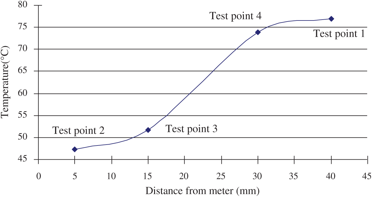
Figure 10: Temperature distribution of test point when the supply water temperature is 90°C
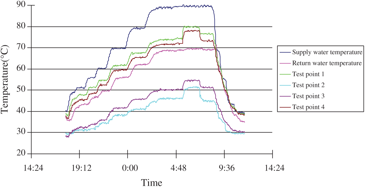
Figure 11: The electronic heat cost allocate meter test result
These results which are shown in Figs. 10 and 11 express that with the supply water temperature rising, the test points have same trend. When the temperature is lower, the slope is higher and the steady time is short. But with the temperature increasing, the slope is lessening and the steady time is long. When the electronic heat cost allocate meter covered by insulate material, the test points temperature also rises and have a time delay which changed with the supply water temperature. The time delay of two test points is similar. All the test points have same trend at process of temperature dropping.
This paper optimizes the system and improves the precise and veracity of the control and measure system of this core problem in radiator thermal performance test equipment. This paper also optimizes the software system and improves the precision of the auto-test system of radiator thermal performance test equipment by the excellence of the computer and the application of the optimized auto-test system. The temperature deviation is very little in the three tests. The flow rate under different conditions have a smaller range from 175 kg/h to 178 kg/h. The average is 176.5 kg/h and the deviation rate are from 1.62% to 1.97% which means the flow rate is constant. The heating was different, the maximum was 4.3 kW and the minimum was 4.2 kW in condition 1; the maximum was 3.3 kW and the minimum was 3.2 kW in condition 2; the maximum was 1.95 kW and the minimum was 1.89 kW in condition 3. But the deviation rate was about 2.9%. So, this radiator thermal performance test equipment has a good stability and high accuracy.
A new electronic heat cost allocate meter test method is proposed by radiator thermal performance test equipment. In the test of electronic heat cost allocate meter, this paper test temperature variation of the temperature measure points and get a result that a backup of heat appeared. In the new electronic heat cost allocate meter, this paper test temperature distribution and get the results of the new electronic heat cost allocate meter. From this test and research, some experiences and references could be obtained for further research and optimize the latest equipment of the heating system.
Funding Statement: This research was supported by the Tianjin Science and Technology Project (Project No. 19JCTPJC44300), The Science & Technology Development Fund of Tianjin Education Commission for Higher Education (Project No. 2018KJ261) and Science and Technology Program Project of Jin Nan District Tianjin (Project Nos. 201805015 & 20190111).
Conflicts of Interest: The authors declare that they have no conflicts of interest to report regarding the present study.
1. Matjaž, P., Gorazd, K. (2018). Experimental analysis of an improved regulation concept for multi-panel heating radiators: Proof-of-concept. Energy, 161, 109–117. [Google Scholar]
2. Witry, A., Al-Hajeri, M. H., Bondok Ali, A. (2005). Thermal performance of automotive aluminum plate radiator. Applied Thermal Engineering, 25(8–9), 1207–1218. DOI 10.1016/j.applthermaleng.2004.09.005. [Google Scholar] [CrossRef]
3. AminHossein, J., Enzo, Z. (2016). Effects of position and temperature-gradient direction on the performance of a thin plane radiator. Applied Thermal Engineering, 105, 467–473. DOI 10.1016/j.applthermaleng.2016.03.018. [Google Scholar] [CrossRef]
4. Embaye, M., AL-Dadah, R. K., Mahmoud, S. (2015). Thermal performance of hydronic radiator with flow pulsation—Numerical investigation. Applied Thermal Engineering, 80, 109–117. DOI 10.1016/j.applthermaleng.2014.12.056. [Google Scholar] [CrossRef]
5. Karl-Villem, V., Andrea, F., Jarek, K. (2019). A combined analytical model for increasing the accuracy of heat emission predictions in rooms heated by radiators. Journal of Building Engineering, 23, 291–300. DOI 10.1016/j.jobe.2019.02.009. [Google Scholar] [CrossRef]
6. Karl-Villem, V., Andrea, F., Tuule, M. K., Jarek, K. (2018). Experimental analysis of emission efficiency of parallel and serial connected radiators in EN442 test chamber. Applied Thermal Engineering, 132, 531–544. DOI 10.1016/j.applthermaleng.2017.12.109. [Google Scholar] [CrossRef]
7. Rahmati, A. R., Gheibi, A. (2020). Experimental and numerical analysis of a modified hot water radiator with improved performance. International Journal of Thermal Sciences, 149, 106175. DOI 10.1016/j.ijthermalsci.2019.106175. [Google Scholar] [CrossRef]
8. Vadiraj, A. H., Ashish, G., Sameer, K. (2011). Thermal radiators with embedded pulsating heat pipes: Infra-red thermography and simulations. Applied Thermal Engineering, 31(6–7), 1332–1346. DOI 10.1016/j.applthermaleng.2011.01.004. [Google Scholar] [CrossRef]
9. Robinson, A. J. (2016). A thermal model for energy loss through walls behind radiators. Energy and Buildings, 127, 370–381. DOI 10.1016/j.enbuild.2016.05.086. [Google Scholar] [CrossRef]
10. Shao, S., Zhang, H., You, S. J., Zheng, W. D., Jiang, L. F. (2019). Thermal performance analysis of a new refrigerant-heated radiator coupled with air-source heat pump heating system. Applied Energy, 247, 78–88. DOI 10.1016/j.apenergy.2019.04.032. [Google Scholar] [CrossRef]
11. Gheibi, A., Rahmati, A. R. (2019). An experimental and numerical investigation on thermal performance of a new modified baseboard radiator. Applied Thermal Engineering, 163, 114324. DOI 10.1016/j.applthermaleng.2019.114324. [Google Scholar] [CrossRef]
 | This work is licensed under a Creative Commons Attribution 4.0 International License, which permits unrestricted use, distribution, and reproduction in any medium, provided the original work is properly cited. |