| Energy Engineering |
DOI: 10.32604/EE.2021.014088
ARTICLE
Transient Free Convection and Heat Transfer in a Partitioned Attic-Shaped Space under Diurnal Thermal Forcing
1School of Mechanical and Mechatronic Engineering, Faculty of Engineering and Information Technology, University of Technology Sydney, Ultimo, NSW 2007, Australia
2Mechanical Engineering Department, University of Canterbury, Christchurch, 8041, New Zealand
3Mechanical Engineering Department, University of Tehran, Tehran, Iran
4Department of Mathematics and Physics, North South University, Dhaka, 1229, Bangladesh
*Corresponding Author: Suvash C. Saha. Email: Suvash.Saha@uts.edu.au
Received: 30 August 2020; Accepted: 19 February 2021
Abstract: One primordial consideration in residential ventilation standards is the comfort of provided to people living in those habitations. This is highly dependent on the thermal and fluid flow conditions, the space geometry and so on. Efficient designs may reduce the energy usage, making the buildings more sustainable over a longer period of time. This study aims to investigate the impact of whole day thermal conditions on the fluid flow structure and heat transfer phenomena, mainly natural convection, inside a partitioned attic-shaped configuration. The Finite Volume Method is applied to solve the governing equations. Sinusoidal thermal boundary condition is applied on the sloping walls to illustrate the characteristics of primary flow through daily cycles. A highly thermal conductive partition was placed vertically at the middle of the cavity. Note that through the partition, only heat could freely transfer between two fluid zones. Results show that, during day time, a stratified fluid flow structure is obtained, which originates from the prevailing conduction heat transfer mechanism, while, for the night-time it changed into a strong convection mechanism which significantly affects the flow structure. These results are particularly important for understanding the fluid dynamics inside the attic shaped building and also designing new residential building.
Keywords: Free convection; attic space; partitioned; diurnal thermal forcing; computational fluid dynamics
Nomenclature
| AR: | Aspect Ratio |
| | Specific Heat ( |
| g: | Gravitational acceleration ( |
| H: | Height of the attic (m) |
| h: | Heat transfer coefficient ( |
| k: | Thermal conductivity ( |
| Nu: | Nusselt Number |
| p: | Pressure (Pa) |
| P: | Period of a cycle (sec) |
| Pr: | Prandtl number |
| q: | Convective heat flux ( |
| Ra: | Rayleigh Number |
| T: | Temperature (K) |
| t: | Time (sec) |
| u, v: | Velocity components ( |
| W: | Half horizontal length of attic (m) |
| x, y: | Coordinates |
| u: | Velocity ( |
| Greek Symbols | |
| | Thermal diffusivity ( |
| | Thermal expansion coefficient ( |
| | Kinematic Viscosity ( |
| | Density ( |
| Subscriptions | |
| air: | Air |
| A: | Amplitude |
| eff: | Effective |
| ref: | Related to a constant temperature |
Free convection heat transfer mechanism within cavities has been considered as one of the significant fluid flows induced from temperature gradient between the boundary and the interior and the eventuated density difference in the working fluid. This issue has attained remarkable consideration throughout the past decades particularly by engineers as it possessed a distinguished significance in houses thermal design, nuclear devices, solar collectors and some other thermal systems. Some wide-ranging review of the current issue can be met in existing literature [1–4]. Morsi et al. [5] numerically analyzed the effects of roof structure and shape on the fluid flow and heat transfer phenomenon inside an enclosure. Their study revealed that, the shape of the top dome has influenced convective heat and fluid flow characteristics greatly. They also concluded that, circular and elliptical shapes lead to higher heat transfer rates compared to others.
Number of studies has been carried out scrutinizing rectangular enclosure [6–11]. However, it is essential to mention that attributed simulations of rectangular geometries cannot describe the whole aspects of buoyancy driven flow inside the cavities with variable or inclined boundaries. Natural convection inside the rectangular geometries has been studying for about four decades. However, the issue of natural convection within triangular cavities or attic shaped spaces, which also happens in many geophysical environments, has got less attention.
According to the climate situation, attic shapes in some buildings are subject to various thermal conditions within a day (24 h). Therefore, the process of natural convection within a building should be exactly exposed and then explained. As thermal and air flow conditions need to provide comfort environment based on residential ventilation standards, the geometry, internal structure and insulation are key causes for an appropriate design. Furthermore, energy usage for ventilation should be concerned for the sake of attaining a higher energy efficient building.
Tzeng et al. [12] provided the Numerical Simulation-Aided Parametric Analysis (NSAPA) method to study the correlation between parameters and natural convection structures in the roof of the attic-shaped enclosures which is useful to design energy-efficient houses. Flack et al. [13,14] accomplished various experiments implementing isosceles triangular enclosures and using air as working fluid for different aspect ratio, AR and Rayleigh number, Ra. The domain received hot/cold energy from horizontal base edge and was cooled/heated from sloping boundaries. Thermal and air flow patterns were scrutinized as well as local and average Nusselt number for inclined boundaries. In case of the base heating and slopping walls cooling, it was concluded that the rise in Rayleigh number causes unstable laminar, natural convection heat transfer when approaching to the critical Rayleigh in which the flow regime changes to the turbulent free convection pattern. Kent [15] did a similar boundary conditions of Flack et al. [13,14]. He conveyed that in the case of base cooling and inclined walls heating, the air flow is stable when the Rayleigh number is high.
Ridouane et al. [16] computationally applied the boundary conditions from Flack et al. [13,14]. The authors figured out a well-suited agreement after comparing Nusselt number attained using numerical and experimental methods. In their subsequent study, they attached baffles on the inclined walls [17] to decrease the heat transfer from the inclined boundaries. Poulikakos et al. [18,19] studied night-time thermal conditions of a triangular enclosure having insulated vertical boundary which represented a complete attic-shaped cavity. Campo et al. [20] utilized Finite Element method to assess seven practical compounds of boundary conditions containing heated/cooled walls as well as insulated edges to catch the fluid flow regime and heated walls Nusselt number. There are many investigations which concentrated on the stability of flow structure [21–24]. The authors stated the fluid flow pattern for various boundary conditions while the single cell shaped at the core of the cavity is stable. They also developed some transitional conditions, depending on the AR and Ra values, after which the cell is subdivided into several minor cells.
Looking from the perspective of thermal system scheme, it can be significant to find out the characteristics of fluid flow and heat transfer between two triangular spaces that are connected through highly conductive walls. This conductive rim has substantial impact on the heat transfer of two fluid regions. Former researchers have pointed out that to have a partition high conductivity; the free convection flow was suppressed compared to non-partitioned space for laminar air flow pattern [25–28].
Nishimura et al. [28] investigated the impact of multiple thin rims on the free convection inside the spaces having AR of 4 and 10 for Ra from 106 to 108 where the number of conductive rims varies between one and four. The researchers stated that the mean Nusselt number has an inverse proportionality with the number of rims. Anderson et al. [29] applied two partitioned walls at a rectangular field center and noticed 20% descending in heat transfer rate compared to single embedded rim. By dividing the rectangular enclosure into six separate zones attenuates heat transfer with a ratio of six [28]. Turkoglu et al. [30] applied four partitions in a rectangular enclosure and concluded that the average Nusselt number enhances with increase in Ra. However, the enclosure AR does not alter the average Nu to a substantial value.
Although several studies have been allocated to study the natural convection within partitioned rectangular or square enclosures, research on triangular spaces has received less attention. However, regarding its priceless applications in various industrial and household fields, this issue has turned much concentration to itself [31–36]. Attic space and heat transfer and air flow related issues are of highly interested issues in this field. Having control over the heat transfer within the triangular enclosure by embedding employing a partition, is still not frequent. Saha et al. [37] implemented a numerical method in a triangular space with partition and suggested that the heat transfer flux between the zones is enhanced for lower AR for a fixed Rayleigh number. Recently, Saha et al. [31–34] have analyzed a sudden and ramp heating/cooling by using scale analysis containing a numerical verification. They performed the development of a transient airflow within the region presenting various stages of the airflow pattern.
Very recently, Cui et al. [38] conducted a 3D numerical simulation of natural convection in a triangular cavity with the top cooling and the bottom heating (all boundaries at constant temperature). They showed that the fluid flow could be classified into three stages: An initial stage, a transitional stage and a quasi-steady stage. Although their comprehensive modelling could be used as an authentic scenario in residential buildings and they presented useful patterns of the flow, but it was limited to some specific time in a day, which did not represent the scenario of a full cycle thermal behavior. A 2D version of this study was conducted Sojoudi et al. [39] by adding a heat source on the bottom surface and a conducting partition along the geometric centerline. Their study was also limited to some specific time of the day. In addition, heat transfer and fluid flow due to non-uniformly distributed surface temperature on the sloping walls was investigated by Saha et al. [40]. In that study a linearly varying sloping wall temperature was propounded while the base boundary was heated uniformly. It was predictable that the inclined walls temperature in the attic-shaped buildings might not be uniform due to sun’s position during the day. Again, this scenario explained the airflow inside the attic in specific times of a day and also described how thermal conditions could linearly change with respect to reference location on the roofs.
All above studies are limited to thermal behavior in some specific time of the day, which may provide us heat transfer and fluid flow scenarios in the steady condition. In a real attic enclosure, however, the region is exposed to different heating/cooling thermal conditions during each thermal period while few works have been dedicated in investigating the periodic cooling or heating (effect of temperature variations during day and night) [41–43]. The authors reported the transient hydrothermal phenomenon originated from cyclic thermal forcing, which is imposed to the roofs.
In this investigation, we have applied FVT to study free convection inside a partitioned attic enclosure under daily thermal condition on the roofs. Influence of Ra and AR are presented on the time-dependent airflow and heat transfer patterns after mesh independency and time-step tests.
2 Description of Mathematical Model
The configuration of the geometry is given in Fig. 1a. Cavity half of the base wall and height are considered as W and H, respectively. A fixed temperature of Tref was applied to the bottom wall. A sinusoidal variation for temperature of inclined walls was considered in which Tref was the mean temperature; TA was the temperature oscillation amplitude and P was the period of the applied boundary condition. Six different points were selected inside the enclosure to capture the temperature time history (Points are named from A to F). No slip condition was applied for all boundaries. The Rayleigh number was defined as Ra ≈ 2gβTAH3/αυ. Four different Rayleigh numbers of 106, 105, 104 and 103, and three AR of 1, 0.5 and 0.2 with the fixed Prandtl number of 0.72 were presumed for the current work. According to Flack’s study [13,14], the upper limit of the Rayleigh number to remain in laminar regime, is about 1.5 × 10⁶ for AR = 0.5. Therefore, we considered lower than the critical values to keep the flow laminar. Moreover, there were mathematical singularities near the sharp corners of the cavity. To avoid these singularities corners were shortened by 5% cut and at determined shortened parts (Fig. 1) no slip and insulated boundary conditions were applied. It is expected that such geometry modification would not significantly alter the total flow progress [37–43].
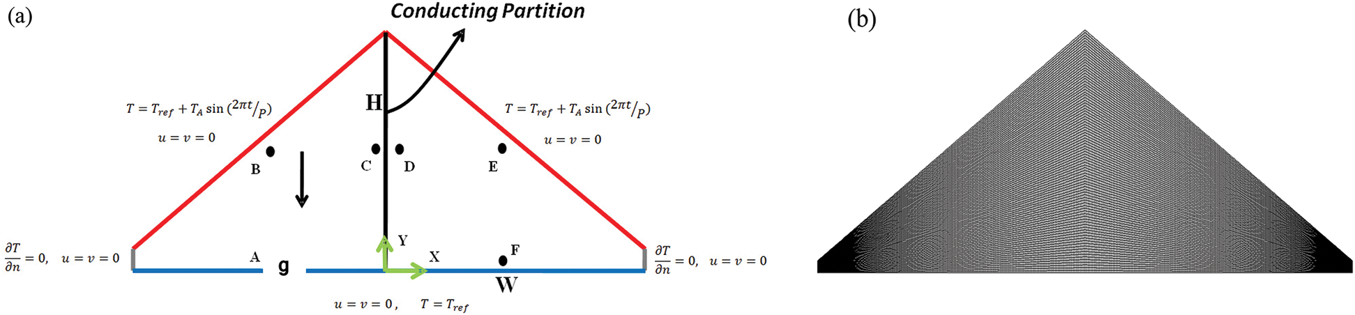
Figure 1: (a) Physical model of the problem, (b) Mesh distribution
Under Boussinesq approximations, the principal equations to model the free convection inside a triangular space containing the continuity, momentum and energy, took the following form:
where u and v are velocity components of the fluid in x and y directions respectively, t is time, ν, ρ, β and α are kinematic viscosity, density, thermal expansion coefficient and thermal diffusivity respectively, T is temperature and g is the gravity acceleration. Initializing and utilizing the specified boundary conditions (described in Section 2), Eqs. (1)–(4) are solved by employing SIMPLE scheme. QUICK scheme is applied to discretize the advection term. A second order implicit time-marching scheme was also used for the unsteady term. Central-differencing with second order precision was used to discretize the diffusion terms.
4 Grid Sensitivity Analysis and Validation
Numerical tests were conducted to assess the necessitous number of meshes and suitable time step size. A representative grid distribution is presented in Fig. 1b. Three different aspect ratios were chosen for this aim. Related assessments to the time-step and grid sizes are also depicted in Fig. 2. The temperature for point C (Fig. 1) inside the cavity was calculated for different grid and time-step sizes for the whole-time simulation. Obtained results showed that the mesh was suitable to resolve the airflow. Based on these computational assessments, the temperature changes at the selected point using finer grid was less than 1.1%. Then, grid with 360 × 75, 360 × 90 and 360 × 120 were chosen for AR = 0.2, 0.5 and 1, respectively. The time-step size is also selected to be 0.5s for all modellings. By verifying the numerical method, the base wall was considered as an adiabatic, but the inclined sidewalls were reserved at constant temperatures. The apparatus used in [13,14] had water tanks with fixed temperatures at the roofs and an adiabatic base wall. The tanks were linked together, and a centrifugal pump was used to circulate the water through the tanks and reservoirs. One tank was heating using heating coils, but the other one was remained at the room temperature or was filled with ice. For a triangular space with AR = 1 without middle partition while Ra = 1.5 × 10⁷ and Pr = 0.72, numerical results of the local Nu for the cold inclined wall was compared with that of Flack [13]. Fig. 3a depicts a good agreement between the current numerical method and former experiments and the maximum error between our numerical simulations and the experimental work is less than 1.5%. Fig. 3b also depicts the comparison of dimensionless temperature for the normal midline using the current numerical simulation and the one for [13] with respect to normalized y.
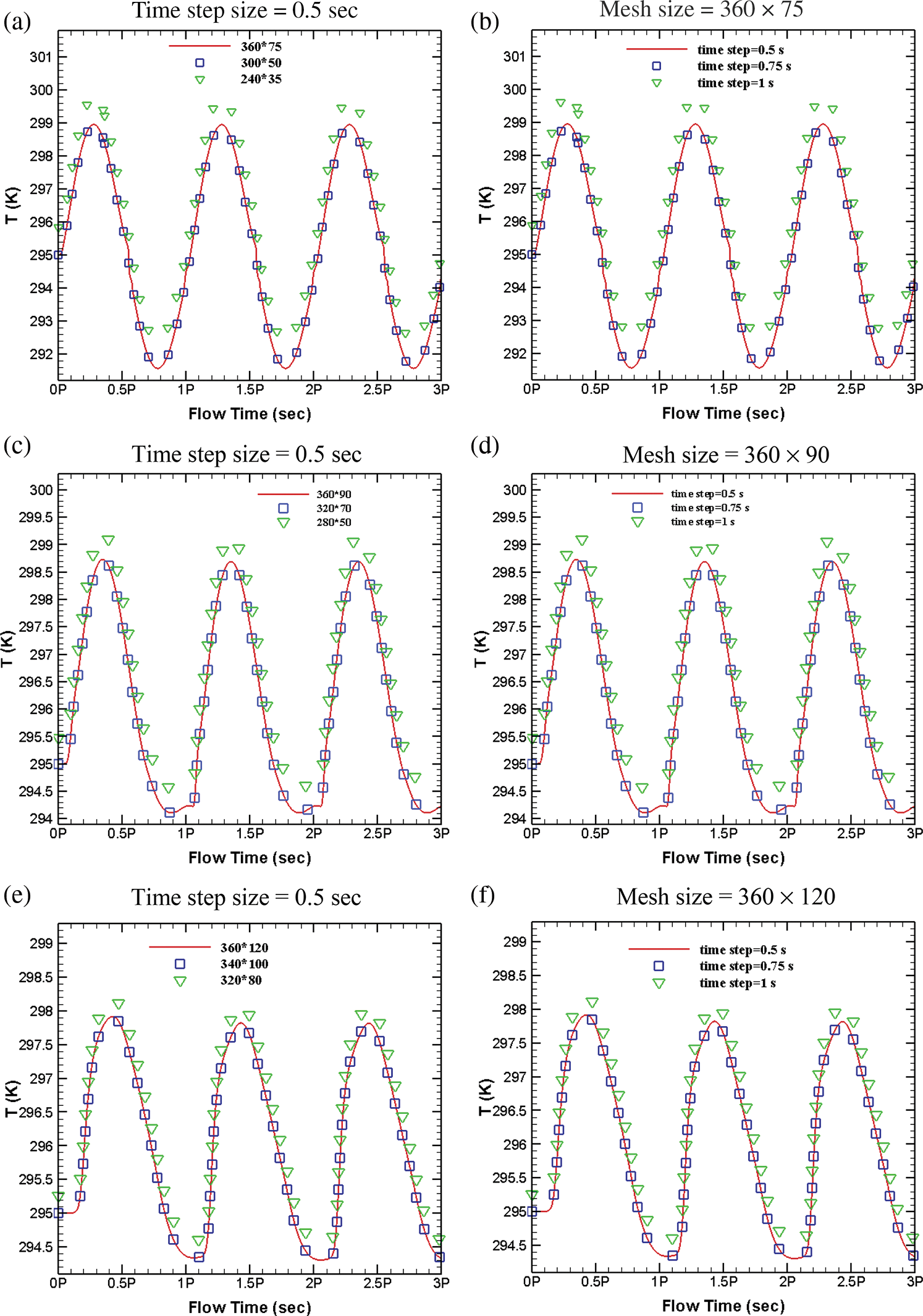
Figure 2: Mesh size and time step size selection tests; (a–b) Temperature of point C for AR = 0.2, Ra = 106, (c–d) Temperature of point C for AR = 0.5, Ra = 106 (e–f) Temperature of point C for AR = 1.0, Ra = 106
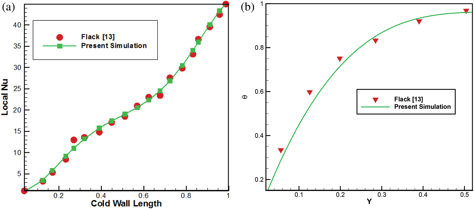
Figure 3: a) Distribution of the local Nu along cold wall boundary condition, comparison with experiment b) Normal midline temperature of the cavity
Since the initial conditions for the air were assumed to be at 295 K and stationary, there was a starting progression of the airflow reaction. Numerically three full cycles were evaluated to reduce the influence of initial progressing flow. It was observed that starting influence for the present numerical method were almost minor and the airflow reaction in the last period was similar to that of former period. The outcomes of the last period (3rd period) are illustrated in the subsequent analysis.
5.1 Transient Temperature and Flow Response
Due to the existing symmetry, the temperature variation at three different points is depicted in Fig. 4 for AR = 0.5 and Ra = 105. As seen from Fig. 1 these points were located at: A = (–0.5, 0.01), B = (–0.4955, 0.2410), and C = (–0.01, 0.25). For temperature time history of Point A, it was obvious that the thermal reaction for periodic thermal forcing of sloping boundaries was 0.1P later for all periods and it could be attributed to the thermo physical characteristics of the air and the mean distance of the point and boundaries. Moreover, the value of temperature variation was higher at midnight time. However, it was not considerable during the all-day with regard to other points and this was related to the proximity of this point to a constant temperature boundary (Base wall, Tref = 295 K). Point B was very close to roof and not only there was no lagging time of temperature change, but also in comparison with the other points there was the most temperature amplitude during all day. At Point C and very close to the highly conductive partition, later response of approximately 0.3P to periodic thermal forcing was observed and higher variation of temperature also reported for daytime rather than midnight time. The other significant result of Fig. 4 was the absence of temperature perturbation near midnight time that was reported by Saha et al. [33] for non-partitioned triangular region. In other words, application of highly conductive partition subsequently suppressed the temperature perturbation and eliminated the disturbances of temperature at specified points and at other locations of the cavity for all cycles.
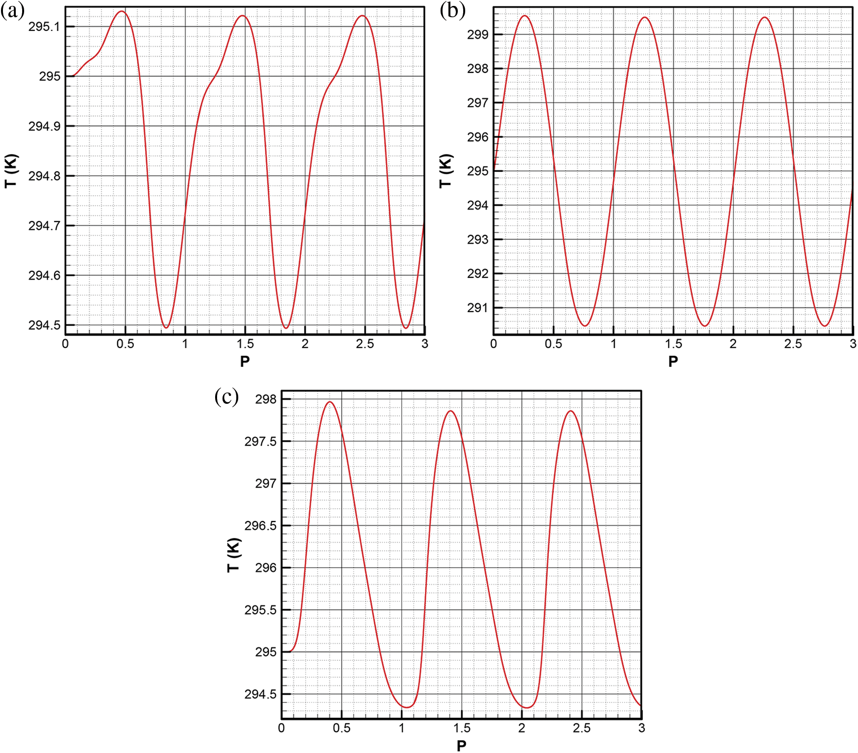
Figure 4: Temperature of Points at AR= 0.5, Ra= 105 a) Point A b) Point B c) Point C
Fig. 5 illustrates horizontal velocity component and temperature profiles evaluated from S line (the vertical line crossing point A and is normal to the bottom edge) during the last cycle, 2P < t < 3P. For t = 2.1P it was perceived that a two-layer structure of the horizontal velocity component was formed, and the velocity value became higher near the inclined wall. Where the bottom layer became oriented to the left corner the direction of top layer was oriented to the partition depicting a rotating cell within the left part of the attic space. As the time progressed, the values of horizontal velocity component at top and bottom layers approached to zero in a time that t was about 2.5P which displayed the end of the daytime. After that, the rotation direction was changed, and top velocity component again had higher value and became oriented to left side while the bottom layer developed to the right side. During the whole cycle, for t = 2.7P the highest velocity was found at top and bottom layer (with opposing directions). This fact confirmed that the rotating velocity of the cell was higher at midnight time rather than day time of the cycle. For temperature profile, it was perceived that during daytime, the air temperature increased from bottom to the inclined wall (from t = 2.1P to t = 2.4P). After that the day time finished, one-layer temperature profile changed into two-layer. The temperature first increased from bottom up to the end of the first layer, then it reduced to bottom temperature at t = 2.7P. After this reduction, temperature enhanced up to the inclined boundary. This process continued up to t = 2.9P and then the temperature profile formed one-layer profile reaching to the start-up time condition.
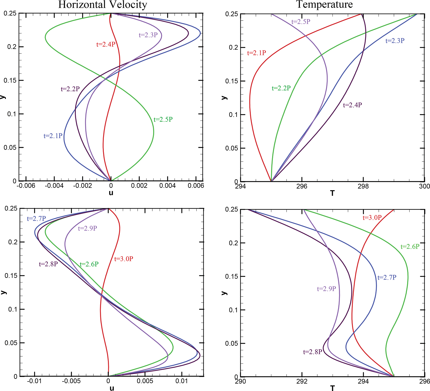
Figure 5: Horizontal Velocity profile (left) and Temperature profile (right) along line S (the vertical line crossing point A and is normal to the bottom edge) for AR = 0.5, Ra = 106
Fig. 6 displays stream function and isotherm contours at t = 25P, 2.5P, 2.75P and 3P for different Rayleigh numbers for fixed AR = 0.5. It was evident that for Ra = 103 two cells were shaped beside the roofs for all day and night and suffered less deformation during the cycle. Size of the rotating cell at day and midnight time was larger than the other times. Temperature contours showed that the heating and cooling pattern during the day and the night time were analogous. For Ra = 104, the average values of stream functions increased due to stronger natural convection effect and again two counter rotating cells were formed at the cavity both sides. For the day time stratified temperature contour was observed that was resulted from heating effect of slopping boundaries. Nevertheless, for the nighttime, especially when t reached to 3P, temperature contour depicted a rising plume near bottom wall and the partition on behalf of stronger heating effect of bottom wall than the inclined walls. With further increase in Ra, this temperature pattern compromised faster, near t = 2.75P for Ra = 105 resulting balanced distribution of temperature till the end of the nighttime (t = 3P). When Ra value reached to 106, average values of the stream function increased, and the elongated cells were formed that affected the entire region of both thermally coupled spaces. Stratified temperature contour was perceived for the day time which can be attributed to the strong heating effect of the inclined walls when natural convection was inactivated. At midnight when Ra was 106, due to stronger effect of natural convection, two rotating cells were formed at each sides of the cavity. More cells were shaped when Ra is high, and this fact needs to be considered in thermal design of attic enclosures. Here, it should be mentioned that in presence of vertical partition we didn’t observe any asymmetric behaviour of the flow within the cavity for any considered Ra. However, for non-partitioned cavity asymmetric, temperature and stream function contours had been reported [33].
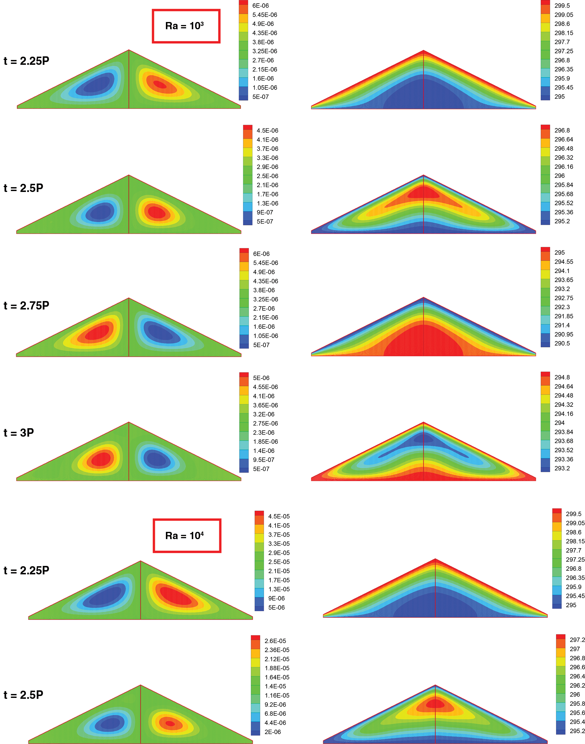
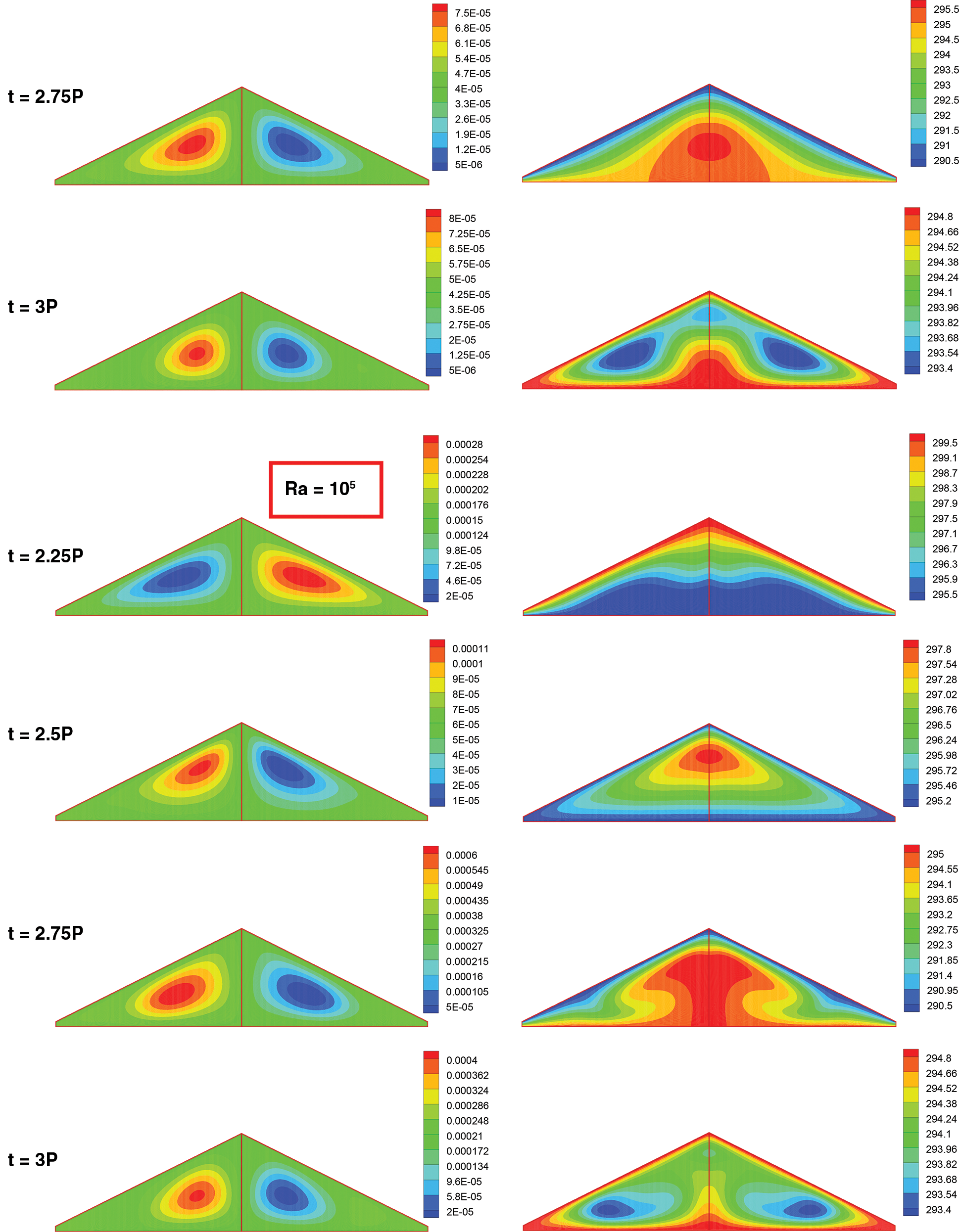
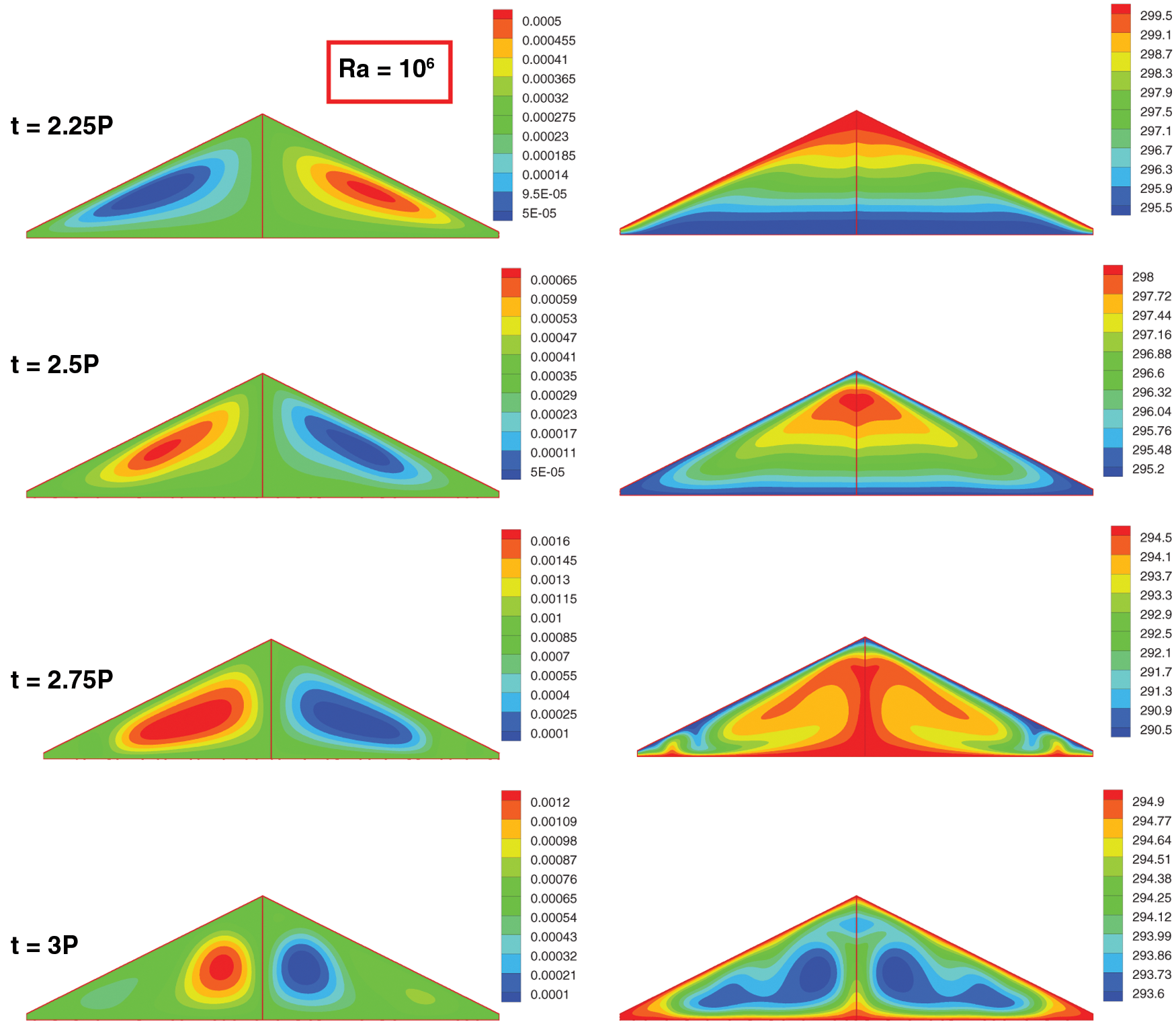
Figure 6: Snapshots of stream function (kg/s) (Left) and temperature (K) (Right) contours for different times and Rayleigh numbers at AR = 0.5
In Fig. 7, effects of aspect ratio on flow and temperature fields in the cavity during a cycle has been scrutinized and presented. Isotherm and stream function contours are reported for Ra = 106. More cells were shaped for AR = 0.2 due to proximity of base wall and roofs and most of them were shaped during the night time. Stratified temperature contour was reported for day time when the conduction heat transfer became dominant. With the increment of AR, number of cells formed during night time reduced to two cells at each side with shortened length regarding lower AR. For AR = 1 identical phenomenon occurred.

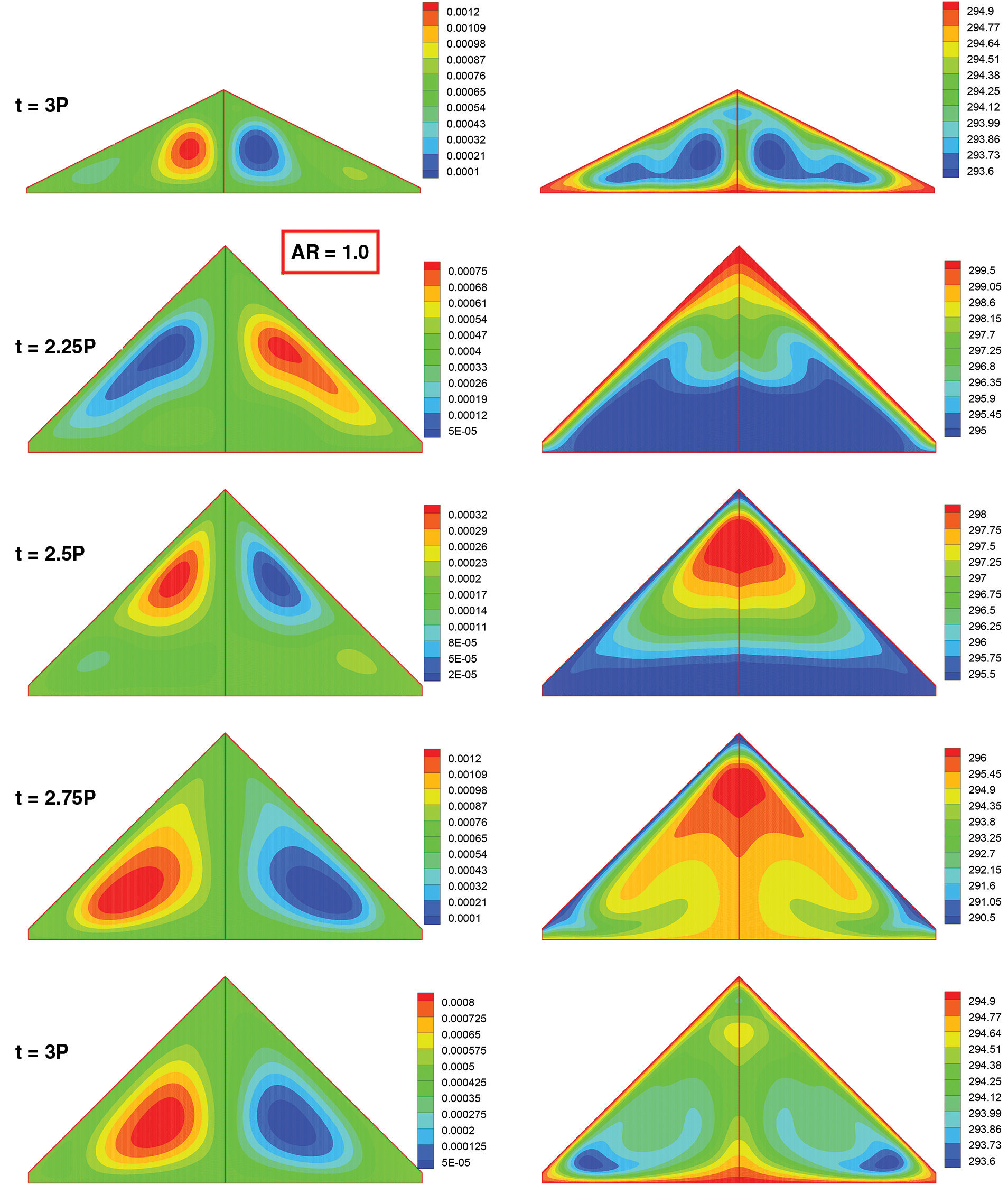
Figure 7: Snapshots of stream function (kg/s) (Left) and temperature (K) (Right) contours for different times and aspect ratios at Ra = 106
5.4 Heat Transfer Phenomenon within the Region
Average Nu was evaluated as following:
Where the efficient heat transfer index was introduced as:
Here q is convective heat flux transferring across a boundary.
Fig. 8 illustrates the average Nusselt number at different Ra and AR = 0.5 for right and, bottom walls and the partition. It was observed that increase in Ra, caused the average Nu of right wall to possess higher amplitude due to higher temperature difference of sinusoidal thermal forcing boundary and bottom wall (See Fig. 8a). Furthermore, the amount of transferred heat to the outside of the cavity through inclined walls at night time was higher when it was compared to the amount of heat transferred into the cavity during the day time. This issue exhibits the prevailing effect of natural convection to conduction heat transfer mechanism for present conditions. The same pattern occurs for bottom wall (See Fig. 8b), however, this was effective in transferring heat into the cavity at night time. This way the energy is conserved.
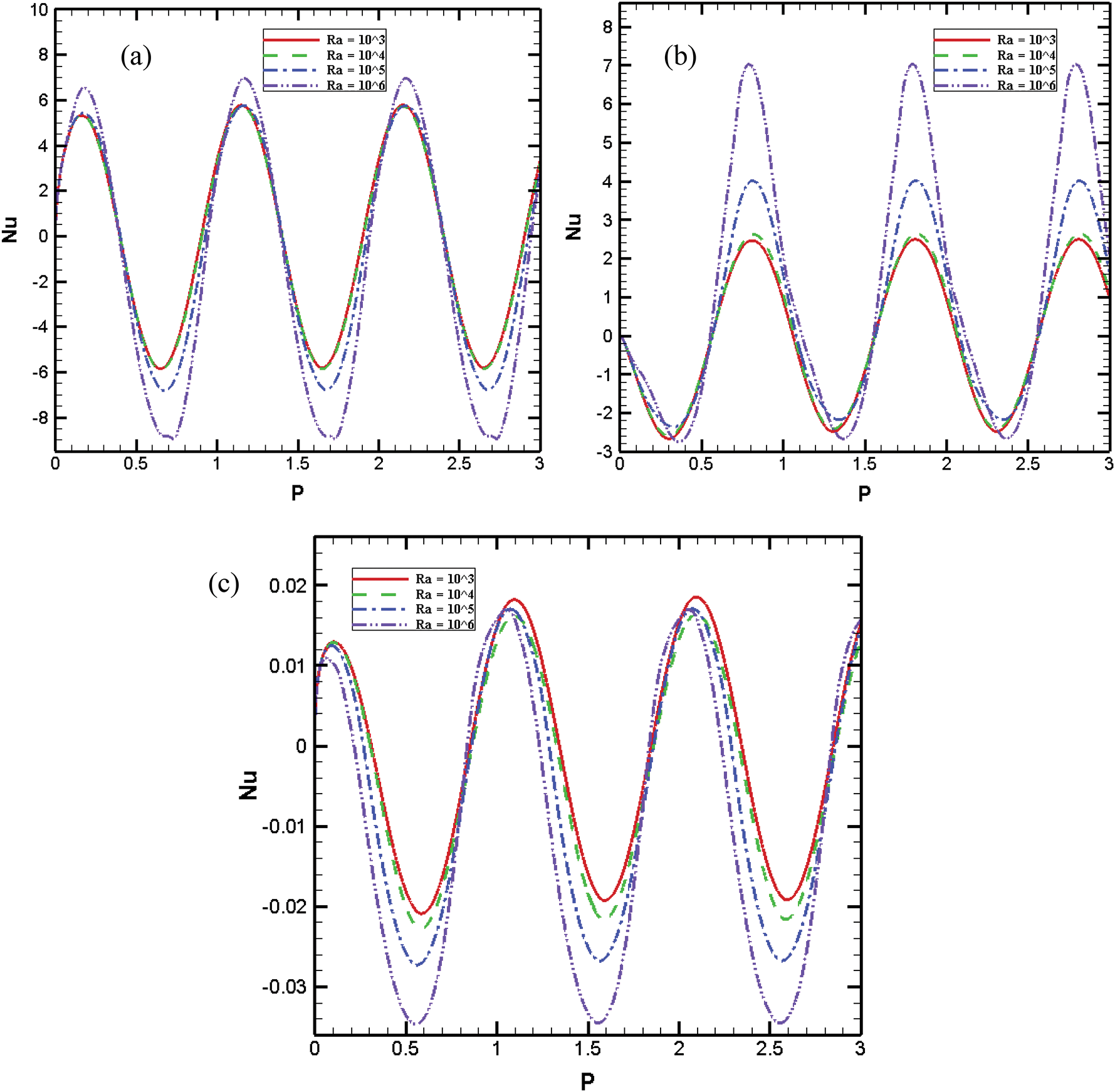
Figure 8: Average Nusselt number at different Ra and AR = 0.5 for a) Right wall b) bottom wall c) Partition
Throughout the day time, equal amount of heat was transferred through the partition for lower Rayleigh numbers, however, for the night time higher amount of heat was transferred for higher Ra. The average Nu values for the partition were very low compared to other boundaries and this fact happened due to the symmetry of the cavity (See Fig. 8c).
Fig. 9 represents average Nusselt number at different AR with Ra = 106 for right and bottom walls and the partition. Because of lower aspect ratio, higher amount of Nu amplitude was perceived for right wall. This can be attributable to the nearness of the boundaries with different temperature during the night and the day time. In Fig. 9b bottom wall average Nu is presented and it is clear that, when AR = 0.2, the same amount of heat transferred into the media at day time was lower than the transferred amount to the outside during the night time. Furthermore, it was noticed that for higher AR, the amount of heat flux throughout the day time approximated zero and with the increase in AR a lagging time was influenced in the average Nu variation. For the partition at various AR, this lagging time is obvious in Fig. 9c.
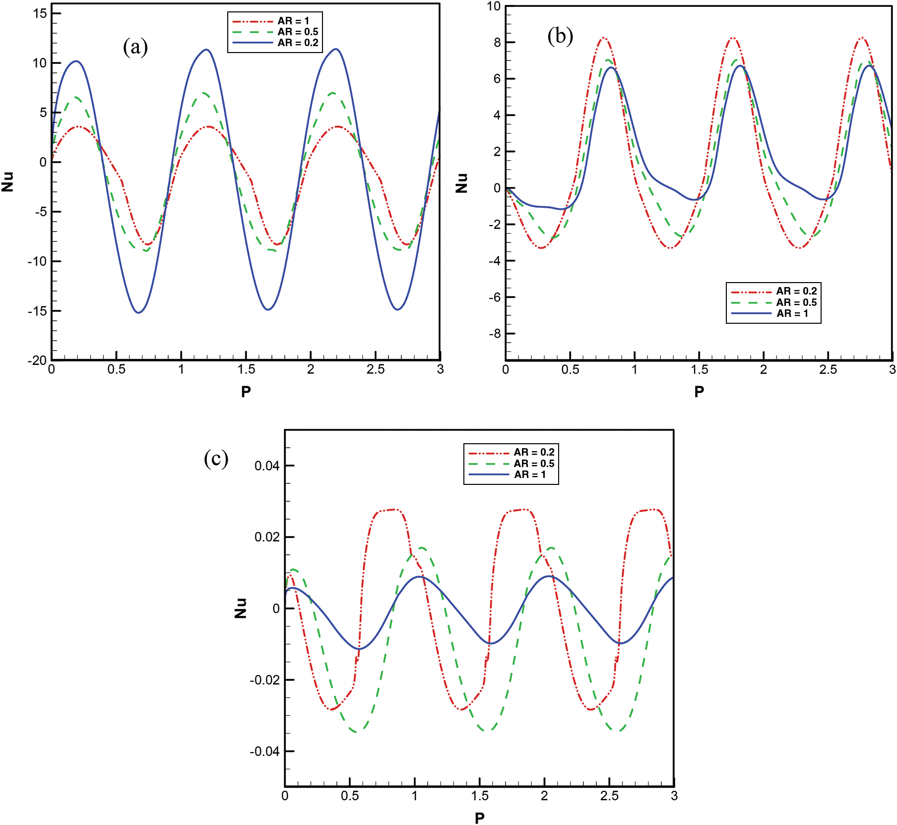
Figure 9: Average Nusselt number at different AR and Ra = 106 for a) Right wall b) Bottom wall c) Partition
Fig. 10 displays the comparison of average Nu in partitioned and non-partitioned cavity at Ra = 106 and AR = 0.5 for right and bottom walls. Results suggested that setting the partition could reduce the amount of average Nu amplitude for both right and bottom walls. This went back to the thermal interaction of the two thermally coupled systems. Such a kind of suppression should be focused when carrying out a thermal design of an attic space.
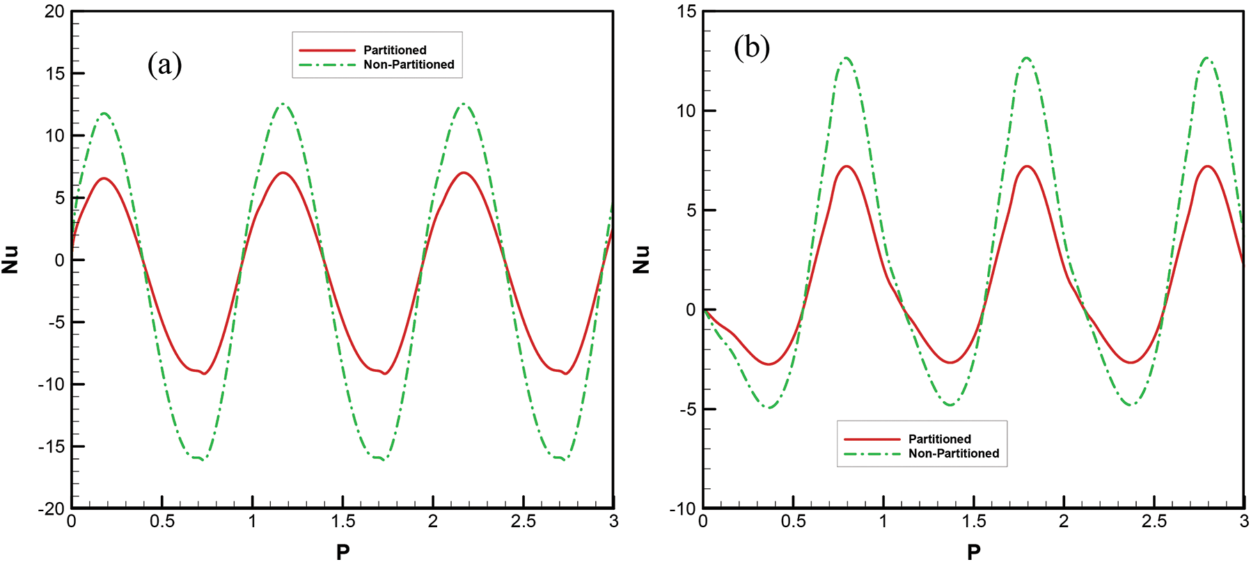
Figure 10: Comparison of average Nu for partitioned and non-partitioned cavity at Ra = 106 and AR = 0.5 a) Right wall b) Bottom wall
Numerical experiments using finite volume technique were accomplished to study the free convection inside attic spaces under daily thermal forcing condition on inclined walls and a highly conductive partition located at the middle of region. The influence of Ra and aspect ratio AR on the unsteady flow development and heat transfer for a fixed Prandtl number of 0.72 was also presented. Important findings of present study can be drawn as follows:
• Using highly conductive partition can suppress the temperature perturbation and eliminates the disturbances of temperature within the cavity for all cycles.
• For daytime stratified temperature contour was observed that resulted from heating effect of slopping boundaries but for nighttime, especially when t reached to 3P, temperature contour showed a rising plume at the proximity of bottom wall and the partition due to stronger heating effect of bottom wall than the inclined walls.
• More cells were shaped for AR = 0.2 due to the proximity of base and roofs and most of them shaped at the nighttime.
• The equal amount of heat was calculated for day and nighttime for lower Ra, but for higher Ra, heat flux rate of nighttime was much higher than that of daytime.
• In presence of vertical partition, symmetric behaviour of the flow was obvious for all Ra and times according to temperature and stream function contours.
• For lower aspect ratio, higher amount of Nu amplitude was seen for right wall, this issue was ascribed to the nearness of the boundaries with different temperature during the night and daytime.
• By the increase in AR, a lagging time of 0.1P was influenced on the average Nu variation.
• The partition suppresses the amount of average Nu amplitude for both right and bottom walls compared to non-partitioned cavity.
Funding Statement: The author(s) received no specific funding for this study.
Conflicts of Interest: The authors declare no conflict of interest. The founding sponsors had no role in the design of the study; in the collection, analyses, or interpretation of data; in the writing of the manuscript, and in the decision to publish the results.
1. Bejan, A. (2013). Convection heat transfer. John Wiley and sons. [Google Scholar]
2. Saeid, N. H. (2017). Natural convection in a square cavity with discrete heating at the bottom with different fin shapes. Heat Transfer Engineering, 39(2), 154–161. DOI 10.1080/01457632.2017.1288053. [Google Scholar] [CrossRef]
3. Sojoudi, A., Saha, S. C., Gu, Y. T. (2015). Natural convection due to differential heating of inclined walls and heat source placed on bottom wall of an attic shaped space. Energy and Buildings, 89(1), 153–162. DOI 10.1016/j.enbuild.2014.12.042. [Google Scholar] [CrossRef]
4. Saha, S. C. (2011). Unsteady natural convection in a triangular enclosure under isothermal heating. Energy and Buildings, 43(2–3), 695–703. DOI 10.1016/j.enbuild.2010.11.014. [Google Scholar] [CrossRef]
5. Morsi, Y. S., Das, S. (2003). Numerical investigation of natural convection inside complex enclosures. Heat Transfer Engineering, 24(2), 30–41. DOI 10.1080/01457630304080. [Google Scholar] [CrossRef]
6. Biswas, N., Mahapatra, P. S., Manna, N. K., Roy, P. C. (2015). Influence of heater aspect ratio on natural convection in a rectangular enclosure. Heat Transfer Engineering, 37(2), 125–139. DOI 10.1080/01457632.2015.1044392. [Google Scholar] [CrossRef]
7. Gangawane, K. M., Bharti, R. P., Kumar, S. (2015). Effects of heating location and size on natural convection in partially heated open-ended enclosure by using Lattice Boltzmann Method. Heat Transfer Engineering, 37(6), 507–522. DOI 10.1080/01457632.2015.1060748. [Google Scholar] [CrossRef]
8. Saha, S., Barua, S., Kushwaha, B., Subedi, S., Hasan, M. N. et al. (2020). Conjugate natural convection in a corrugated solid partitioned differentially heated square cavity. Numerical Heat Transsfer, Part A: Applications, 78(10), 541–559. DOI 10.1080/10407782.2020.1803609. [Google Scholar] [CrossRef]
9. Anderson, R., Bejan, A. (1980). Natural convection on both sides of a vertical wall separating fluids at different temperatures. Journal of Heat Transfer, 102(4), 630–635. DOI 10.1115/1.3244363. [Google Scholar] [CrossRef]
10. Acharya, S., Tsang, C. H. (1985). Natural convection in a fully partitioned, inclined enclosure. Numerical Heat Transfer A, 8, 407–428. [Google Scholar]
11. Tong, T. W., Gerner, F. M. (1986). Natural convection in partitioned air-filled rectangular enclosures. International Communications in Heat and Mass Transfer, 13(1), 99–108. DOI 10.1016/0735-1933(86)90076-X. [Google Scholar] [CrossRef]
12. Tzeng, S. C., Liou, J. H., Jou, R. Y. (2005). Numerical simulation-aided parametric analysis of natural convection in a roof of triangular enclosures. Heat Transfer Engineering, 26(8), 69–79. DOI 10.1080/01457630591003899. [Google Scholar] [CrossRef]
13. Flack, R. D. (1980). The experimental measurement of natural convection heat transfer in triangular enclosures heated or cooled from below. Journal of Heat Transfer, 102(4), 770–772. DOI 10.1115/1.3244389. [Google Scholar] [CrossRef]
14. Flack, R. D., Witt, C. L. (1979). Velocity measurements in two natural convection air flows using a laser velocimeter. Journal of Heat Transfer, 101(2), 256–260. DOI 10.1115/1.3450956. [Google Scholar] [CrossRef]
15. Kent, E. F. (2009). Numerical analysis of laminar natural convection in isosceles triangular enclosures. Proceedings of the Institution of Mechanical Engineers, Part C: Journal of Mechanical Engineering Science, 223(5), 1157–1169. DOI 10.1243/09544062JMES1122. [Google Scholar] [CrossRef]
16. Ridouane, E. H., Campo, A., McGarry, M. (2005). Numerical computation of buoyant airflows confined to attic spaces under opposing hot and cold wall conditions. International Journal of Thermal Sciences, 44(10), 944–952. DOI 10.1016/j.ijthermalsci.2005.03.008. [Google Scholar] [CrossRef]
17. Ridouane, E. H., Campo, A. (2007). Effects of attaching baffles onto the inclined walls of attic frames for purposes of energy conservation. Heat Transfer Engineering, 28(2), 103–111. DOI 10.1080/01457630601023419. [Google Scholar] [CrossRef]
18. Poulikakos, D., Bejan, A. (1983). Natural convection experiments in a triangular enclosure. Journal of Heat Transfer, 105(3), 652–655. DOI 10.1115/1.3245635. [Google Scholar] [CrossRef]
19. Poulikakos, D., Bejan, A. (1983). The fluid dynamics of an attic space. Journal of Fluid Mechanics, 131, 251–269. DOI 10.1017/S0022112083001317. [Google Scholar] [CrossRef]
20. Campo, E. M., Sen, M., Ramos, E. (1988). Analysis of laminar natural convection in a triangular enclosure. Numerical Heat Transfer A, 13, 353–372. [Google Scholar]
21. Salmun, H. (1995). The stability of a single-cell steady-state solution in a triangular enclosure. International Journal of Heat and Mass Transfer, 38(2), 363–369. DOI 10.1016/0017-9310(95)90031-4. [Google Scholar] [CrossRef]
22. Farrow, D. E., Patterson, J. C. (1993). On the response of a reservoir sidearm to diurnal heating and cooling. Journal of Fluid Mechanics, 246, 143–161. DOI 10.1017/S0022112093000072. [Google Scholar] [CrossRef]
23. Kent, E. F. (2011). Laminar natural convection in isosceles triangular roofs in wintertime conditions. Heat Transfer Engineering, 31(13), 1068–1081. DOI 10.1080/01457631003640339. [Google Scholar] [CrossRef]
24. Asan, H., Namli, L. (2000). Laminar natural convection in a pitched roof of triangular cross-section: Summer day boundary conditions. Energy and Buildings, 33(1), 69–73. DOI 10.1016/S0378-7788(00)00066-9. [Google Scholar] [CrossRef]
25. Duxbury, D. (1979). An interferometric study of natural convection in enclosed plane air layers with complete and partial central vertical divisions. Doctoral dissertation, University of Salford. [Google Scholar]
26. Cuckovic-Dzodzo, D. M., Dzodzo, M. B., Pavlovic, M. D. (1999). Laminar natural convection in a fully partitioned enclosure containing fluid with nonlinear thermophysical properties. International Journal of Heat and Fluid Flow, 20(6), 614–623. DOI 10.1016/S0142-727X(99)00053-3. [Google Scholar] [CrossRef]
27. Xu, F., Patterson, J. C., Lei, C. (2009). Heat transfer through coupled thermal boundary layers induced by a suddenly generated temperature difference. International Journal of Heat and Mass Transfer, 52(21–22), 4966–4975. DOI 10.1016/j.ijheatmasstransfer.2009.06.004. [Google Scholar] [CrossRef]
28. Nishimura, T., Shiraishi, M., Nagasawa, F., Kawamura, Y. (1988). Natural convection heat transfer in enclosures with multiple vertical partitions. International Journal of Heat and Mass Transfer, 31(8), 1679–1686. DOI 10.1016/0017-9310(88)90280-3. [Google Scholar] [CrossRef]
29. Anderson, R., Bejan, A. (1981). Heat transfer through single and double vertical walls in natural convection: Theory and experiment. International Journal of Heat and Mass Transfer, 24(10), 1611–1620. DOI 10.1016/0017-9310(81)90069-7. [Google Scholar] [CrossRef]
30. Turkoglu, H., Yücel, N. (1996). Natural convection heat transfer in enclosures with conducting multiple partitions and side walls. Heat and Mass Transfer, 32(1–2), 1–8. DOI 10.1007/s002310050084. [Google Scholar] [CrossRef]
31. Saha, S. C., Patterson, J. C., Lei, C. (2010). Natural convection in attics subject to instantaneous and ramp cooling boundary conditions. Energy and Buildings, 42(8), 1192–1204. DOI 10.1016/j.enbuild.2010.02.010. [Google Scholar] [CrossRef]
32. Saha, S. C., Patterson, J. C., Lei, C. (2010). Natural convection in attic-shaped spaces subject to sudden and ramp heating boundary conditions. Heat and Mass Transfer, 46(6), 621–638. DOI 10.1007/s00231-010-0607-5. [Google Scholar] [CrossRef]
33. Saha, S. C., Patterson, J. C., Lei, C. (2010). Natural convection and heat transfer in attics subject to periodic thermal forcing. International Journal of Thermal Sciences, 49(10), 1899–1910. DOI 10.1016/j.ijthermalsci.2010.05.010. [Google Scholar] [CrossRef]
34. Saha, S. C. (2011). Unsteady natural convection in a triangular enclosure under isothermal heating. Energy and Buildings, 43(2–3), 695–703. DOI 10.1016/j.enbuild.2010.11.014. [Google Scholar] [CrossRef]
35. Holtzman, G. A., Hill, R. W., Ball, K. S. (2000). Laminar natural convection in isosceles triangular enclosures heated from below and symmetrically cooled from above. Journal of Heat Transfer, 122(3), 485–491. DOI 10.1115/1.1288707. [Google Scholar] [CrossRef]
36. Cui, H., Xu, F., Saha, S. C., Liu, Q. (2019). Transient free convection heat transfer in a section- triangular prismatic enclosure with different aspect ratios. International Journal of Thermal Sciences, 139, 282–291. DOI 10.1016/j.ijthermalsci.2019.02.023. [Google Scholar] [CrossRef]
37. Saha, S. C., Gu, Y. T. (2014). Transient air flow and heat transfer in a triangular enclosure with a conducting partition. Applied Mathematical Modelling, 38(15–16), 3879–3887. DOI 10.1016/j.apm.2013.10.006. [Google Scholar] [CrossRef]
38. Cui, H., Xu, F., Saha, S. C. (2015). A three-dimensional simulation of transient natural convection in a triangular cavity. International Journal of Heat and Mass Transfer, 85, 1012–1022. DOI 10.1016/j.ijheatmasstransfer.2015.02.055. [Google Scholar] [CrossRef]
39. Sojoudi, A., Saha, S. C., Xu, F., Gu, Y. T. (2016). Transient air flow and heat transfer due to differential heating on inclined walls and heat source placed on the bottom wall in a partitioned attic shaped space. Energy and Buildings, 113(5), 39–50. DOI 10.1016/j.enbuild.2015.12.036. [Google Scholar] [CrossRef]
40. Saha, S. C., Gu, Y. T. (2015). Natural convection in a triangular enclosure heated from below and non-uniformly cooled from top. International Journal of Heat and Mass Transfer, 80(8), 529–538. DOI 10.1016/j.ijheatmasstransfer.2014.09.047. [Google Scholar] [CrossRef]
41. Saha, S. C., Sefidan, A. M., Sojoudi, A. (2020). Unsteady natural convection within an attic-shaped space subject to sinusoidal heat flux on Inclined walls. Energy Engineering., 117(1), 1–17. DOI 10.32604/EE.2020.010412. [Google Scholar] [CrossRef]
42. Saha, S. C., Patterson, J. C., Lei, C. (2010). Natural convection and heat transfer in attics subject to periodic thermal forcing. International Journal of Thermal Sciences, 49(10), 1899–1910. DOI 10.1016/j.ijthermalsci.2010.05.010. [Google Scholar] [CrossRef]
43. Saha, S. C., Patterson, J. C., Lei, C. (2007). Effect of aspect ratio on natural convection in attics subject to periodic thermal forcing. ANZIAM Journal, 49, 677–691. DOI 10.21914/anziamj.v48i0.109. [Google Scholar] [CrossRef]
 | This work is licensed under a Creative Commons Attribution 4.0 International License, which permits unrestricted use, distribution, and reproduction in any medium, provided the original work is properly cited. |