| Energy Engineering |
DOI: 10.32604/EE.2021.014378
ARTICLE
Optimization of Combustion Characteristics and Fuel Injection Timing of a New Type Dual-Pit Combustor Rotary Engine
1School of Energy and Power Engineering, Jiangsu University, Zhenjiang, 212013, China
2Department of Mechanical Engineering, National University of Singapore, 119260, Singapore
*Corresponding Author: Jianfeng Pan. Email: mike@ujs.edu.cn
Received: 22 September 2020; Accepted: 29 October 2020
Abstract: In order to improve the performance of the rotary engine, this paper has designed a new type of dual-pit rotary engine combustion chamber structure, and compares the combustion and emission characteristics with the rotary engine with a traditional combustion chamber. The existence of the dual-pit combustion chamber strengthens the overall vortex intensity in the cylinder, effectively promotes the mixing process of fuel and air in the cylinder, the maximum combustion pressure in the cylinder increased by 8.6%, significantly increases the diffusion combustion speed, and significantly improves the dynamic performance of the rotary engine. On this basis, the effects of fuel injection timing parameters on fuel distribution, combustion and emission characteristics were studied. Fuel distribution is more even and dispersed during injection in the later stage of compression. When the fuel injection timing was 105°BTDC in the middle of the compression phase, the matching effect of fuel distribution law and ignition scheme was the best. When the injection timing was 75°BTDC and 85°BTDC in the late compression stage, the mass fraction of NOx remained at a low level. The correlation between soot generation and the change of fuel injection timing was weak. When the injection time was 85°BTDC, the soot generation remained at a relatively high level.
Keywords: Rotary engine; combustion chamber structure; spray combustion characteristics; injection strategy; experiment and simulation
The rotary engine is a special type of engine invented by a German engineer, Wankel, driven by actual demand. Compared to the traditional reciprocating piston engine, the rotary engine is directly matched by the triangular rotor and the eccentric shaft, and continuously performs high-speed one-way rotation in the cylinder for power output while avoiding the influence of large vibration and alternating load. Vibration has been greatly reduced, which is more conducive for high-speed development [1,2]. The rotary engine has a wide range of applications and high reliability. It is currently widely used in military aviation, vehicle power, and micro-power systems. Although rotary engines have been used in some fields, problems such as high fuel consumption and excessive emissions have not been fundamentally resolved.
Due to the unique structure and working principle of the rotary engine, as the compression process progresses, the space in the cylinder becomes narrower and longer. The vortex formed in the cylinder during the intake and compression stages is gradually broken into one-way flow due to compression. Near the dead point, there is a flow field distribution law dominated by unidirectional flow, which is not conducive for flame propagation to the back of the combustion chamber, resulting in incomplete fuel combustion.
In order to optimize the performance of the rotary engine, a series of studies have been carried out on the rotary engine. First of all, in the design of the combustion chamber structure, Gao et al. designed a new type of opposed rotary piston engine [3,4], and also used 3D numerical simulation methods to investigated the in-cylinder combustion and emissions characteristics of the hydrogen fuelled opposed rotary piston engine using 3D numerical simulation method at various engine speeds and full load conditions [5]. Abraham et al. measured the in-cylinder indicator diagrams of the rotary engine under different working conditions, performed a numerical simulation of the combustion process of the premixed natural gas rotary engine, studied the combustion chamber pits, and the influence of its shape on the combustion process when placed in the middle [6,7]. Li et al. numerically simulated the combustion process of gasoline and diesel rotor engines [8,9]. The research group also simulated and studied the influence of operating parameters on the combustion process of natural gas engines [10], and systematically simulated and analyzed the influence of different combustion chamber structures caused by different pit positions on the rotary engine. The research provides a relevant theoretical basis for the performance improvement and optimal design of the rotary engine [11].
Secondly, in terms of in-cylinder flow and fuel spray characteristics, The existing research results show that the distribution law of the flow field in the cylinder and the fuel spray characteristic parameters play crucial roles in the formation of the mixture and the improvement of the combustion characteristic [12], This is because a good mixture distribution and combustion characteristics not only depend on the fuel spray characteristic parameters, but also on the distribution of the flow field in the cylinder. Hamady et al. used visualization technology to study the in-cylinder air flow movement process and the kerosene-air mixing process. The research results show that the vortex formed in the cylinder at the early stage of compression has a significant effect on the turbulence intensity in the early combustion process, and the fuel injection parameters are particularly important for the improvement of incomplete combustion [13]. Morita conducted research on the fuel spray characteristics of rotary engines and the formation process of the mixture. The research results show that the airflow movement in the cylinder has an important influence on the formation of the mixture in the cylinder, and the injection timing parameters are important for the optimization of the spray characteristics [14]. For the gasoline rotary engine, Hasegawa et al. studied the influence of the injection timing parameters on the distribution of the mixture in the cylinder. The results show that the advancement of the injection timing is conducive for the formation of the mixture in the front of the combustion chamber, which is not conducive for the combustion chamber. Concerning the formation of the rear mixture [15], Votaw et al. used the method of numerical simulation to study the influence of parameters such as injection angle and injection position on the combustion characteristics under the condition of heavy oil as fuel. The research results show that when the injection position is at the top dead center position and the injection angle is 65°, the combustion characteristics are significantly improved [16]. In terms of the optimization of the intake and exhaust system and sealing performance, Shimizu et al. improved the volumetric efficiency of the rotary engine by installing a turbocharger [17]; Picard et al. optimized the seal to improve the sealing performance of rotary engines [18], Alrbai et al. investigated the effect of using hydrogen as a fuel additive in natural gas homogeneous charge compression ignition free piston engine [19,20]. In addition, our research team has also conducted a series of studies on the adaptability of gaseous fuels, diesel spray characteristics, and mixture formation and flame propagation [21,22], and conducted experimental studies on diesel spray characteristics under rotary engine conditions. After focusing on the analysis of the influence of the spray environment back pressure on the spray characteristics, the research results show that: Within a certain range, with the delay of the injection time, the environment back pressure value increases. It effectively reduces the spray penetration distance and increases the spray cone angle value, which provides a test basis for optimizing the injection timing of diesel rotary engines.
In summary, the current research in the literature mainly includes the improvement of the multi-fuel characteristics of the rotary engine, the study of the distribution of the flow field in the cylinder, the optimization of the fuel spray characteristics, the improvement of the intake and exhaust system and the sealing performance, etc. Gao et al. reviewed thermal management methods for fast catalyst light-off, with the purpose of decreasing cold start and warm up emissions [23]. Recently, with the continuous optimization of spray characteristics, the requirements for the fuel injection system are getting higher and higher, and the research on the flow field in the cylinder of the rotary engine mainly involves the study of the existing flow field distribution in the cylinder. Research on the optimization and improvement of the flow field distribution in the cylinder is relatively lacking.
For the optimization of the flow field in the cylinder of the rotary engine, the optimization of the cylinder block profile is restricted due to the special structure of the rotary engine. Therefore, the optimization of the flow field in the cylinder of the rotary engine can only be carried out through the optimization design of the combustion chamber structure. For rotary engines, diesel fuel is obviously more advantageous in terms of power output. In addition, if the combustion is in the later stage, organizing effective air movement in the cylinder can create favorable conditions for accelerating the flame propagation speed in the cylinder and promoting the diffusion combustion process. In view of the above analysis, for the diesel rotary engine, starting from the optimization of the design of the combustion chamber structure, the optimization of the flow field distribution law and the improvement of the spray characteristics are combined to carry out research, which has important value and significance.
Therefore, this paper takes the diesel rotary engine as the research object. Firstly on the basis of the traditional combustion chamber, the optimization of the design of the dual-pit combustion chamber of the diesel rotary engine was carried out, and then the numerical model of the diesel rotary engine under the dual-pit combustion chamber structure was established. Based on the built model, a comparative analysis was firstly made on the influence of the dual-pit combustion chamber structure on the flow field distribution and combustion characteristics in the cylinder, and then the influence of the injection timing parameters on the mixture distribution and combustion characteristics was analyzed, focusing on the analysis to achieve a comprehensive optimization analysis process that combines the flow field distribution law with the improvement of spray characteristics, and creates conditions for fundamentally solving the problem of incomplete fuel combustion in the cylinder of the rotary engine.
2 Structure Establishment of Geometric Model and Meshing of Rotary Engine
2.1 Geometric Design Parameters of Dual-Pit Combustion Chamber
As shown in Fig. 1, on the basis of the traditional combustion chamber and ensuring constant compression ratio, the design of a new type of combustion chamber structure was completed, which was named dual-pit combustion chamber here. But unlike the traditional combustion chamber structure, the dual-pit combustion chamber is mainly composed of three parts: The front guide wall, the rear guide wall and the middle guide table. Among them, the diversion wall is composed of three arcs with different sizes, and specific structure and dimensions are shown in Fig. 1.
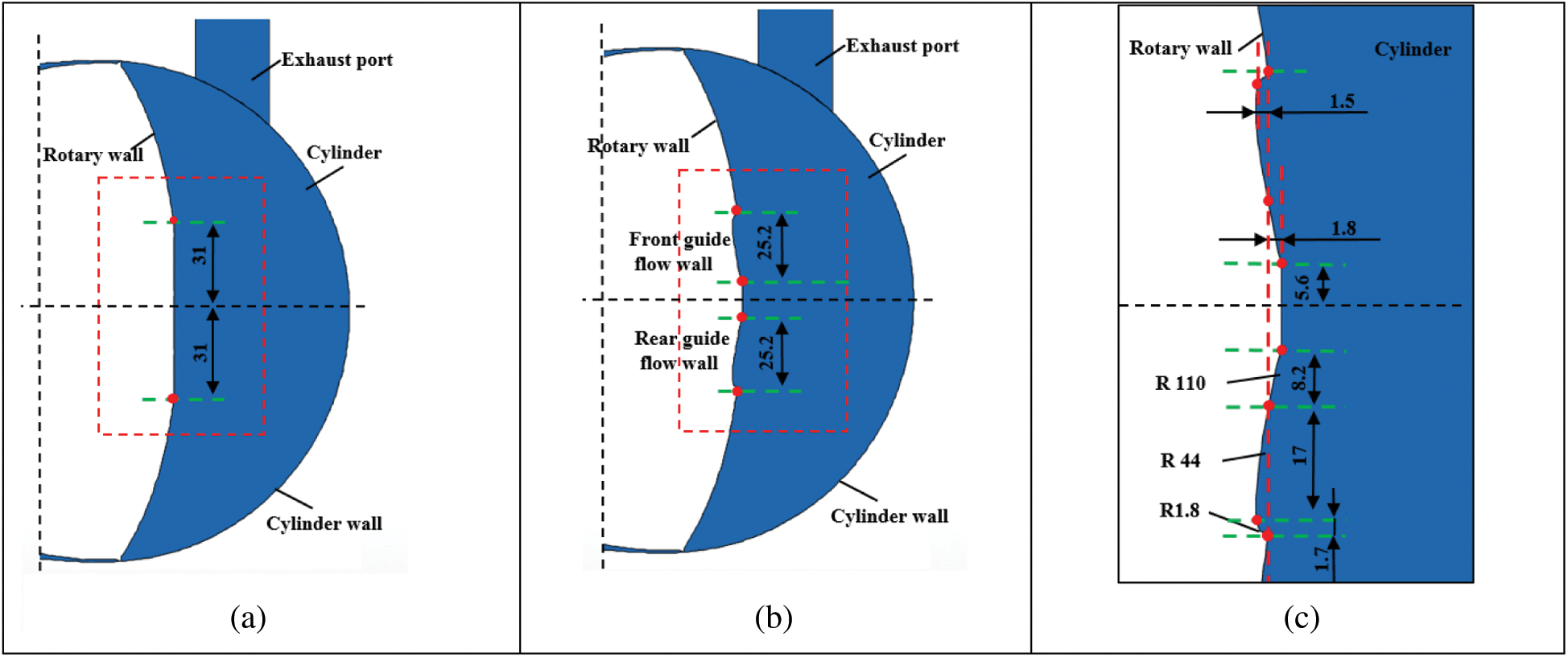
Figure 1: Two types of combustion chamber structure and size parameter diagram, (a) Traditional combustion chamber, (b) Dual-pit combustion chamber, (c) Dimension drawing of dual-pit combustion chamber
2.2 Basic Parameter Setting of the Rotary Engine
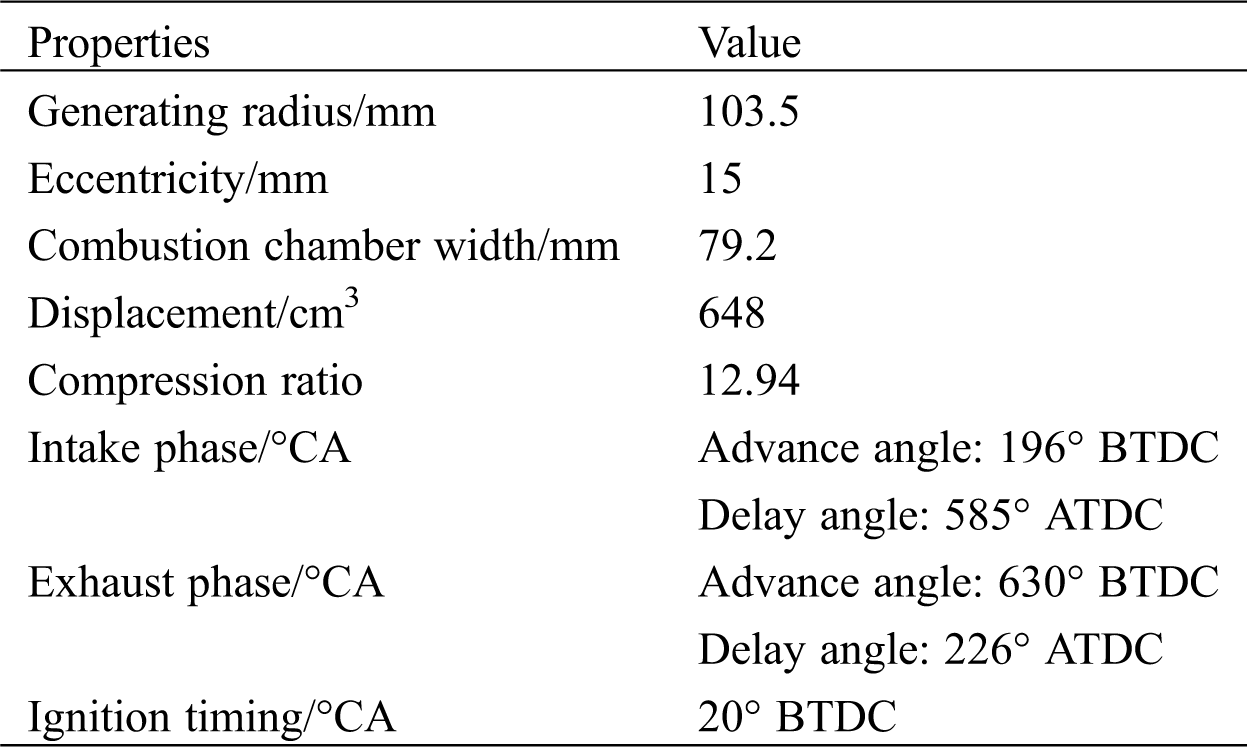
Fig. 2 is the geometric model of the rotary engine. As shown in the Fig. 2, the rotary engine studied in this paper was derived from the literature [24]. The rotary engine mainly includes cylinder block, triangular rotor, eccentric shaft, front and rear end cover and other components. This model uses diesel as the fuel. For the ignition system, in view of the relatively narrow space in the cylinder at the time of the rotary engine ignition, adopted dual spark ignition scheme, the ignition time was 20°BTDC. The basic parameters of the specific rotary engine are shown in Tab. 1. For the fuel injection system, the fuel injection pressure for this research was 60 MPa, the diameter of the injection hole was 0.18 mm, and the injection duration was 1 ms. The specific injection position was as shown in Fig. 2.
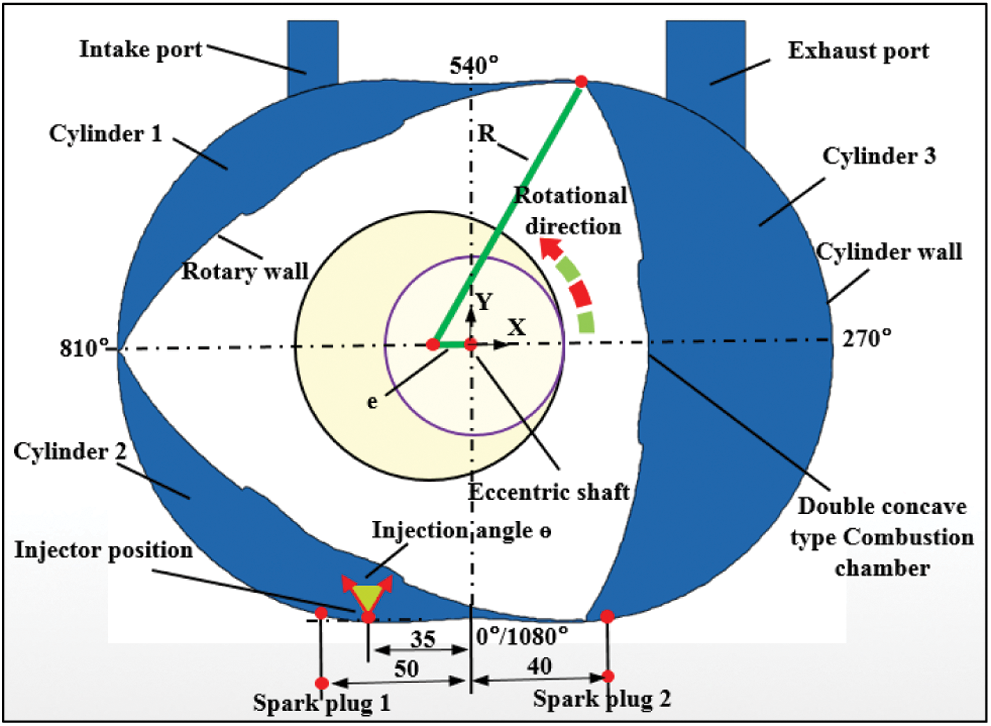
Figure 2: Schematic diagram of a rotary engine model
Table 1: Basic parameters of rotary engine
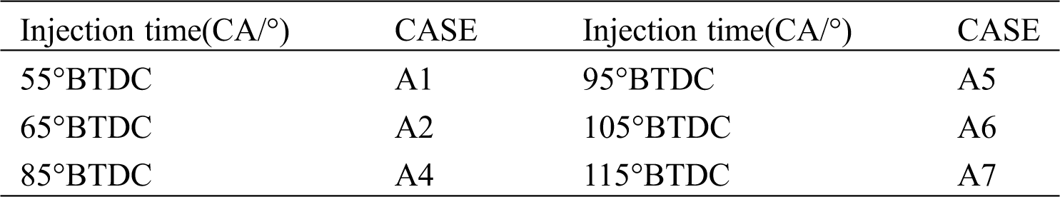
In this paper, for the comparative analysis of the traditional combustion chamber and the dual-pit combustion chamber, the same injection timing and ignition timing were used. The specific engine-related parameter settings are shown in Tab. 2. In the optimization process of injection timing, the optimization range of fuel injection timing was 55°BTDC to 115°BTDC. See Tab. 3 for specific parameter settings of the engine.
Table 2: Parameters of two combustor structures analysis
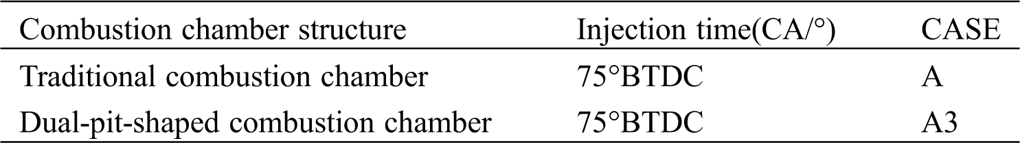
Table 3: Fuel injection timing research parameter table
2.3 Implementation and Grid Division of Moving Grid
During the operation of the rotary engine, the volume of the three cylinders periodically changes with the rotation of the rotor, and the volume of the intake and exhaust ports of the rotor engine is fixed. Therefore, the volume of the three cylinders were set as dynamic grid in the area, and by writing a C program, the grid was continuously updated with the change of the crank angle. In order to avoid the phenomenon of negative volume during the dynamic grid update process, the triangle’s unstructured grid type was selected for grid division. Fig. 3 is a dynamic grid diagram under different crankshaft angles. Through the verification of grid independence, the final grid size was 1.4 mm.
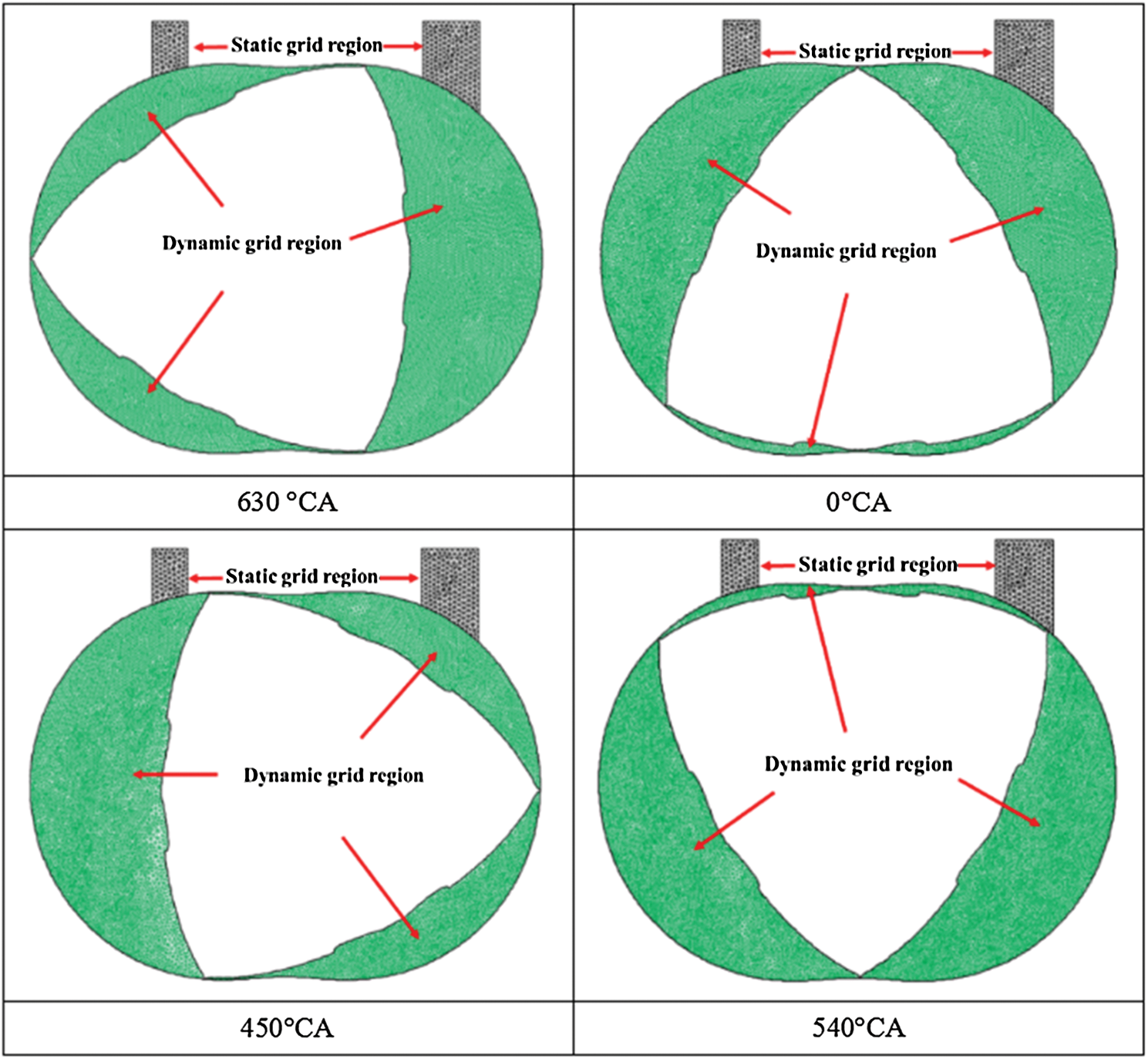
Figure 3: Mesh model of rotary engine with different eccentric shaft angles
3 Model Setting Conditions and Verification
3.1 Basic Model and Initial Boundary Conditions
The air flow in the cylinder of a rotary engine is a compressible viscous flow, and accurate simulation of the influence of turbulence is the key to in-cylinder simulation [25]. The RNG model is modified from the standard model and enhances the dissipation of turbulent flow energy. It can better predict the changes in strength and pressure during the oscillation process [26], and it has the potential for higher precision prediction of complex flows. For the complex flow inside the rotary engine, the simulation calculation accuracy is high [27], so the RNG turbulence model was selected. For the spray model, the discrete droplet model (DPM) was selected. For the broken sub-model [28], because of the spray under this model, the droplet size distribution trend was in good agreement with the experimental data, so the KH-RT model was selected as the fragmentation sub-model. The eddy dissipation concept (EDC) model is an extension of the eddy dissipation model. It can couple detailed chemical reaction mechanisms into the turbulent reaction flow. Therefore, the combustion model adopted the EDC model and coupled the 29-component, 52-step reaction of n-heptane simplification mechanism. According to the literatures [28,29], the thermodynamic NO model and the rapid NO model can better simulate the generation of NOx. Therefore, the thermodynamic NO generation mechanism and the rapid NO generation mechanism were selected for simulation calculation. In addition, because the Moss-Brookes model has high simulation accuracy for the soot generation during the combustion of high-carbon molecules, the Moss-Brookes model was chosen.
For the boundary conditions, the intake and exhaust areas of the rotary engine were set as pressure inlet and pressure outlet respectively, and the pressure values at the intake and exhaust ports were set to 1 atm. According to experience, the wall temperature of the triangular rotor was set to a constant temperature of 400 K. The other working conditions adopted in this paper are the speed of 4000 r/min and the excess air coefficient of 1.25.
3.2.1 Verification of the Turbulence Model
The RNG model has good adaptability to the simulation of the complex flow inside the rotary engine, and for the accuracy of the simulation results in this model, a detailed comparative analysis and research has been carried out in reference [27]. As shown in the Fig. 4, comparing the PIV test images with the simulation results shows that the selected RNG model has a high degree of predictive ability for the flow field in the cylinder of the rotary engine.

Figure 4: PIV flow field test bench and flow field image
3.2.2 Verification of Spray Model
In order to verify the reliability of the spray model, in reference [30] for the same model and working condition and adding the rotary engine working condition to the constant volume combustion bomb, the diesel spray data under the rotary engine working condition was obtained, and compared with the FLUENT numerical simulation results. The verification of the spray model under multiple working conditions was completed. As shown in Fig. 5, regarding the spray penetration distance, the difference between the experimental result and the numerical simulation result was 3.79%. Regarding the average droplet size, the difference between the experimental and simulated results was 3.13%. For the spray profile, the experimental results were in good agreement with the numerical simulation results. In addition, considering the unique flow field distribution law in the cylinder of the rotary engine, the cylinder temperature and pressure value of the rotary engine are lower than that of the reciprocating piston engine [31]. Therefore, in order to ensure the reliability of the spray model, there was further use of experiments. The data completed the model verification. As shown in Fig. 6, the difference between the experimental result and the numerical simulation result for the spray penetration distance was 7.25%, and for the spray pattern, the difference between the experimental result and the simulation result was small. In summary, the experimental verification results show that the spray model used is reliable.

Figure 5: Validation of spray model in constant volume bomb environment
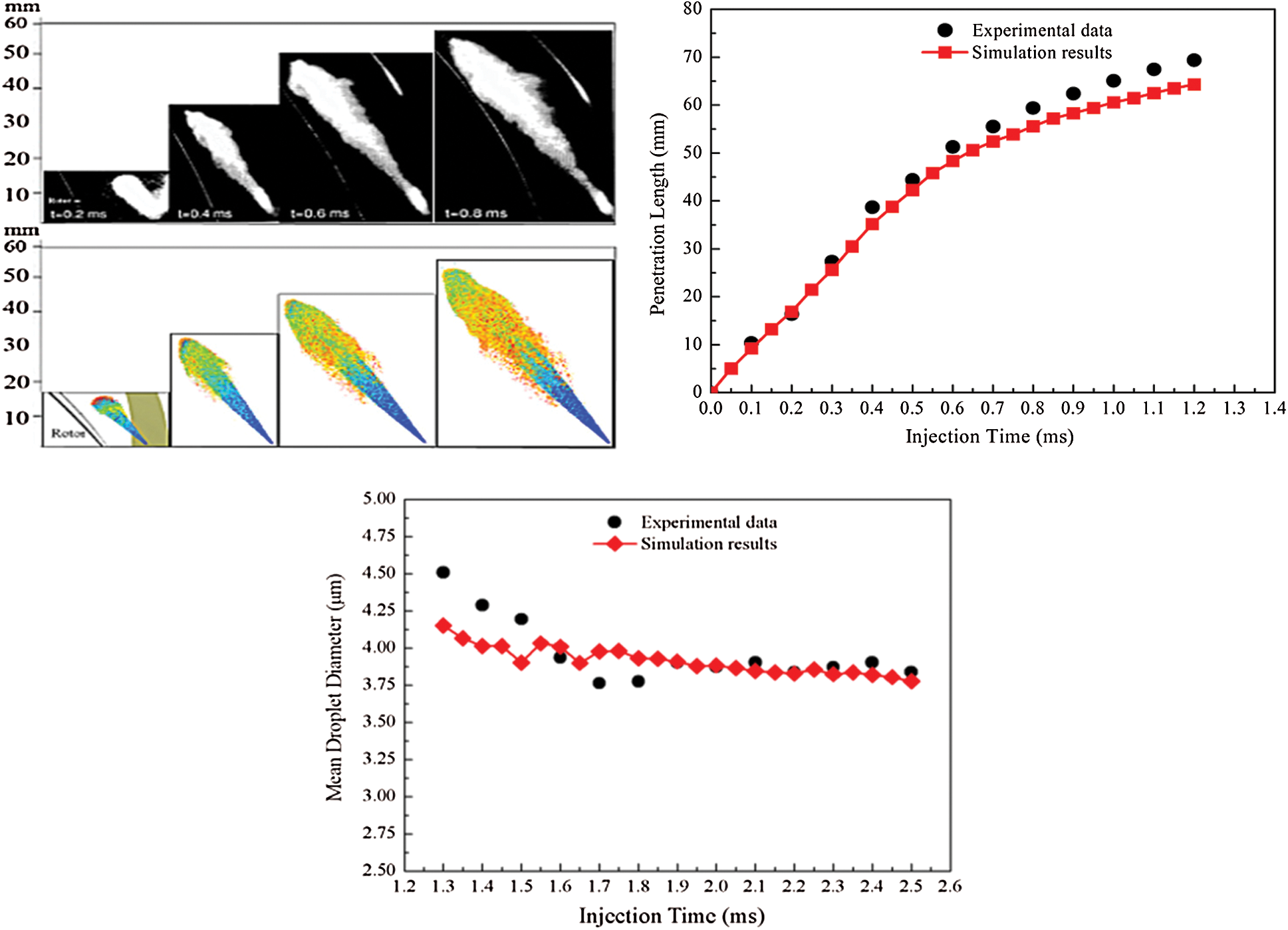
Figure 6: Validation of spray model for rotary engine in cylinder environment
3.2.3 Verification of the Combustion Model
In order to verify the reliability of the EDC combustion model in literature, a model coupled with the simplified mechanism of n-heptane was established, and the numerical simulation results were compared with the experimental data in literature [32]. The results are shown in Fig. 7. It is shown that the simulation value was slightly higher than the experimental value because the leakage loss between adjacent cylinders and the effect of residual exhaust gas in the cylinder were ignored in the simulation. The difference between the experimental and the simulated results was about 10%, but in general, the simulated results were compared with the experimental ones. The results have good consistency, thus verifying the reliability of the EDC model.

Figure 7: Validation of a combustion model
4.1 Influence of the Dual-Pit Combustion Chamber Structure on the Flow Field and Velocity Distribution in the Cylinder
Fig. 8 is the flow field distribution and velocity distribution diagram of the conventional combustion chamber structure and the dual-pit combustion chamber structure at 180°BTDC. In this paper, the vortex with the center axis of rotation parallel to the eccentric axis is defined as swirl. It can be seen from the Fig. 9 that in the early stage of the compression stage, the flow field distribution area in the cylinder was mainly divided into two regions, swirl1 and swirl2, and from the flow field distribution diagram, the region of swirl2 in CaseA3 was significantly larger than the region of swirl2 in CaseA. Compared with swirl1 in CaseA, the area of swirl1 in CaseA3 had been further expanded. From the velocity distribution cloud, we can see that compared with CaseA, the high-velocity area in CaseA3 was significantly expanded, while the overall higher-velocity area was expanded to a certain extent, and there was a downward trend. After analysis, it was found that this was due to the presence of a front arc guide wall and a rear arc guide wall in the dual-pit combustion chamber, which played an important role in guiding the wall surface during the change of the flow field in the cylinder. In the early stage of the compression, this made the swirl2 obvious enhancement. In addition, due to the counterclockwise increase in swirl2, it not only played a key role in guiding the downward development of high-speed airflow in the upper part, but also strengthened swirl1 to a certain extent, resulting in the continuous expansion and direction of the higher flow velocity area in the cylinder under the ever-expanding trend.
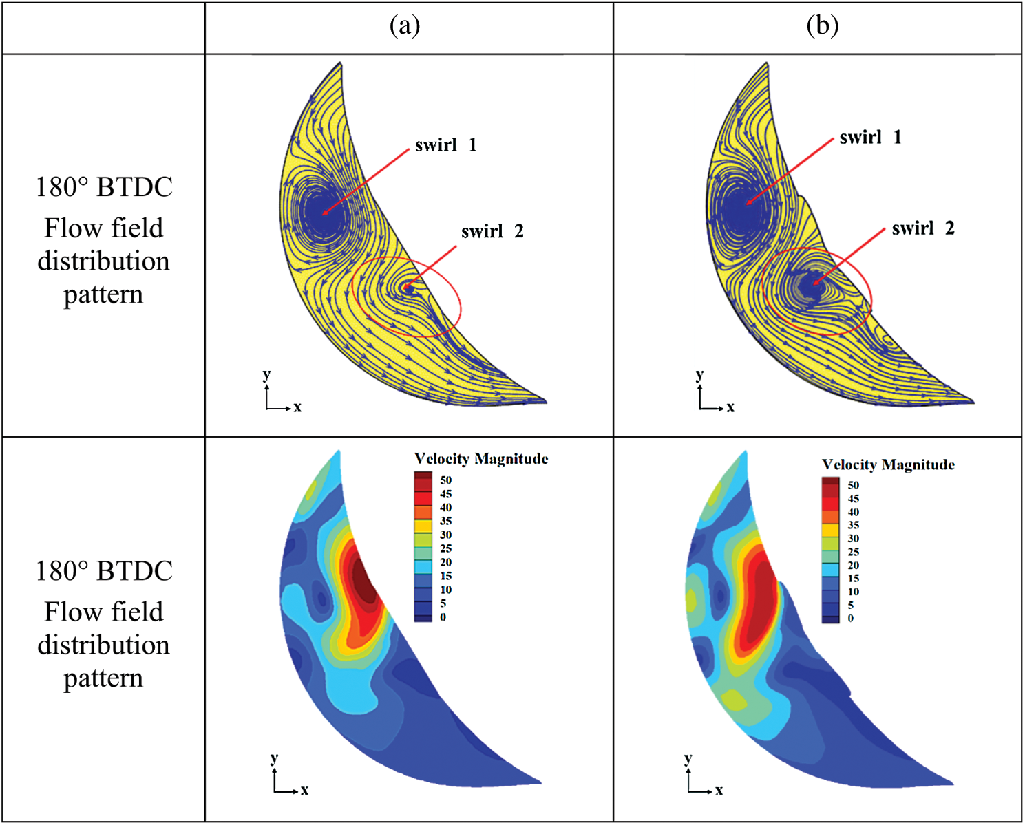
Figure 8: Comparison between flow field and velocity distribution 180°BTDC, (a) Traditional combustion chamber, (b) Dual-pit combustion chamber
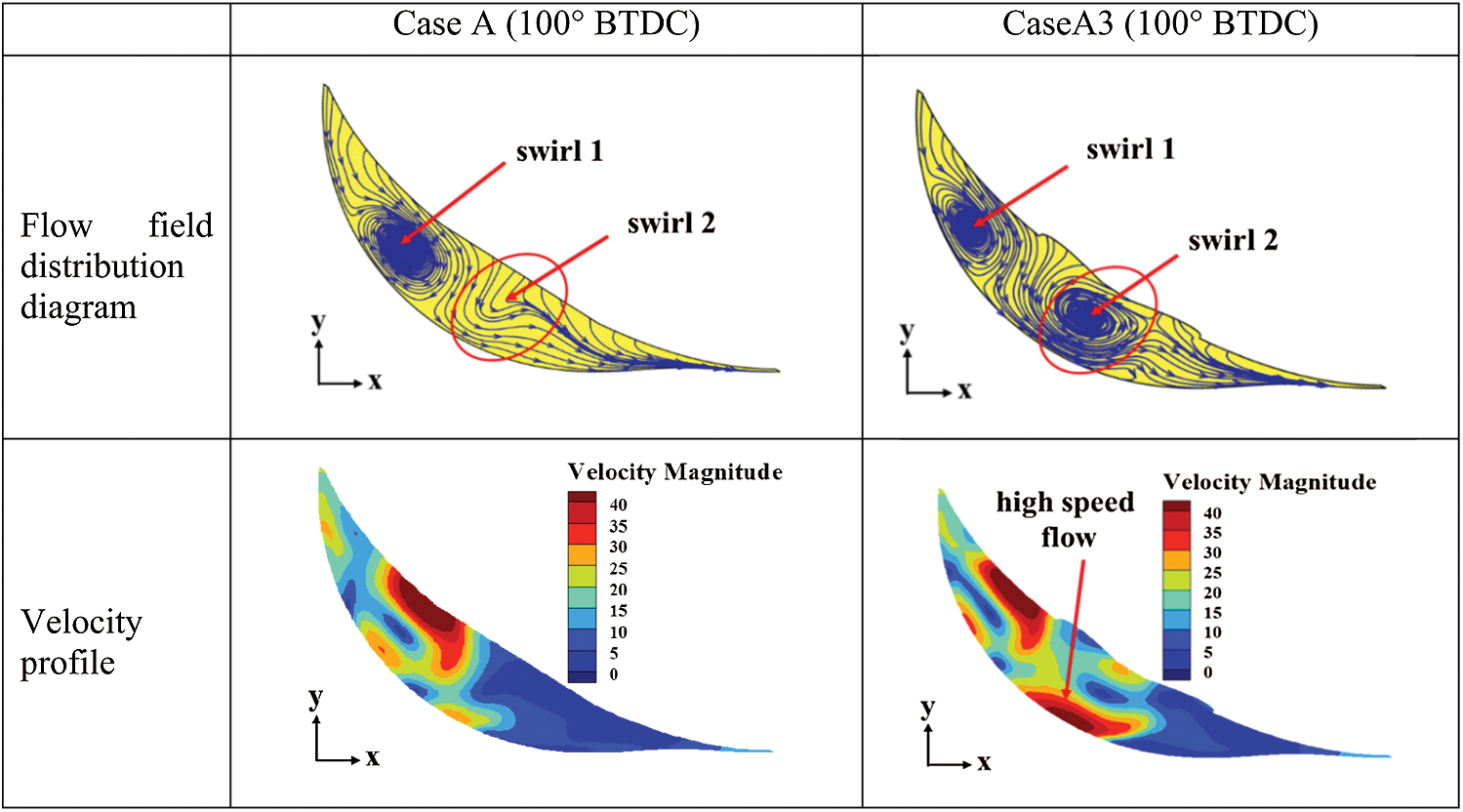
Figure 9: Comparison between flow field and velocity distribution 100°BTDC
At the time of 100°BTDC, the distribution of flow field in the cylinder was still mainly divided into two parts, swirl1 and swirl2, and with CaseA score, the area of swirl2 in CaseA3 increases significantly. From the velocity distribution cloud, it can be seen that the area adjacent to the air velocity in CaseA3 was significantly enlarged with CaseA, and unlike the case where there is only one high-speed flow area in CaseA, there are obviously two high-speed flow areas in CaseA3. After analysis, it was found that this was due to the continuous compression stage, the internal space of the rotor cylinder was getting narrower and smaller, and the swirl1 and swirl2 spaces were squeezed. However, as the compression process progressed, the leading of the dual-pit combustion chamber, the flow wall and the rear guide wall continued to produce a wall-guiding effect on the air flow in the cylinder, further strengthening the swirl2 in the middle of the cylinder at this time. Therefore, compared to the swirl2 scale in Fig. 8, the swirl2 at 100°BTDC was relatively more obvious, which was the result of the continuous operation of the front and rear guide walls of the dual-pit combustion chamber during compression. In view of the enhancement of swirl2, another high-speed flow area was obviously formed near the wall surface of the cylinder below it, further strengthened the overall vortex strength in the cylinder.
As shown in the Fig. 10 above, at 40°BTDC, the distribution law of the flow field in the cylinder was that on the basis of the existence of the original swirl1 and swirl2, then swirl3 was generated. Compared to CaseA, the swirl2 area in CaseA3 was significantly enlarged at this time. At the time of 20°BTDC, due to the continuous reduction of the space in the cylinder during the compression process, swirl1 and swirl3 were extruded and disappeared, and only swirl2 existed in the cylinder. At the time of TDC, the space inside the cylinder was already very narrow and long, and swirl2 disappeared due to squeezing, and the vortex in the cylinder was almost completely broken into a unidirectional flow. Therefore, in the late stage of the compression process, the space in the cylinder became narrower and longer, and the vortex in the cylinder was further compressed and broken into three small areas of vortices, but the swirl2 under the dual-pit combustion chamber structure still maintained a large vortex intensity.

Figure 10: Distribution diagram of flow field under different eccentric axis angle
In summary, during the entire compression stroke, with the gradual reduction of the space in the cylinder, vortex flow was generated, developed, and finally broken into a unidirectional flow. Compared to the traditional combustion chamber, the presence of the front guide wall and the rear guide wall in the dual-pit combustion chamber significantly increased the swirl intensity of swirl2, which significantly increased the overall airflow velocity in the cylinder, thereby further strengthening the cylinder. The overall vortex intensity, if combined with the injection strategy, can create conditions for optimizing the distribution of the mixture in the cylinder of the rotor engine, accelerating the flame propagation speed, and thus improving the combustion characteristics.
4.2 Influence of the Structure of the Dual-Pit Combustor on the Combustion Characteristics
As shown in Fig. 11, the overall change trend of the in-cylinder pressure under the two combustion chamber structures was basically the same. At 20°ATDC, the in-cylinder combustion pressure reached the maximum value at the same time. Specifically, from the ignition time of 20°BTDC to TDC, the difference between the two pressure curves was not large. Compared with the pressure curve under traditional combustion chamber conditions, the structure of the dual-pit combustion chamber was significantly increased. At 20°ATDC, the in-cylinder combustion pressure increased by 8.6%, and the combustion pressure reached the maximum value of 3.7 MPa. The crank angle corresponding to the highest combustion pressure was 20°ATDC, although it is the same as the reciprocating piston engine. The range of crank angle corresponding to the maximum combustion pressure is slightly different [33], but it has good consistency with the relevant test data of the rotor engine [31,34]. Afterwards, as the expansion stroke continued from 20°ATDC to 40°ATDC, the pressure values of the two different combustion chamber structures began to decrease, and the gap between the two pressure curves was basically constant. After 40°ATDC, the gap between the two pressure curves gradually decreased.

Figure 11: Cylinder pressure curve contrast diagram
Fig. 12 is a graph of the change in burned mass fraction at different crankshaft angles. As shown in the Fig. 12, from TDC to 60°ATDC, the burned mass fraction of fuel in the dual-pit combustion chamber condition increased at a faster rate than in the conventional combustion chamber condition. Since the burned mass fraction at the moment corresponding to the highest combustion pressure is an important parameter of the combustion velocity in the reaction cylinder, at this time at 20°ATDC corresponding to the highest combustion pressure, the burned mass fraction under the condition of the dual-pit combustion chamber The fraction was 44%, the burned mass fraction under the traditional combustion chamber structure was 40%, the burned mass fraction increased by 4%, and in the subsequent time, the burned mass fraction in the dual-pit combustion chamber condition remained relatively larger.

Figure 12: Change in the burned mass fraction
From the above analysis, it can be seen that after the top dead center time, the combustion speed under the condition of the dual-pit combustion chamber increased significantly, and the combustion pressure in the cylinder also increased significantly. In order to further reveal the mechanism of the dual-pit combustion chamber structure on the flow field and flame propagation process in the cylinder, Fig. 13 shows the streamline diagram and CH2O distribution diagram at 20°ATDC, 40°ATDC and 60°ATDC.
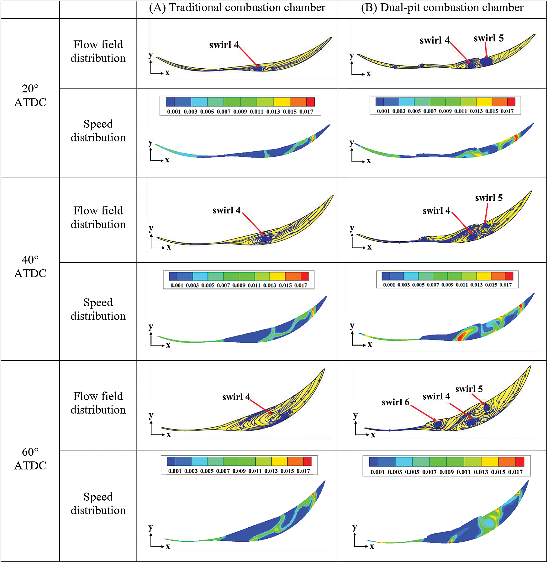
Figure 13: Cylinder flow field and CH2O distribution pattern
As shown in the Fig. 14 above, with the progression of the expansion process, the space in the cylinder near the front guide wall first rapidly increased, creating space for the vortex in the cylinder to form again. At the time of 20°ATDC and 40°ATDC, only the expansion vortex swirl4 existed in the flow field under the traditional combustion chamber structure, and the other areas were mainly unidirectional flow. Under the action of the front guide wall, the inside of the dual-pit combustion chamber exhibited a flow field distribution rule dominated by swirl4 and swirl5.

Figure 14: Fuel distribution diagram 40°BTDC and 20°BTDC (a) Injection after compression (b) Compressed medium injection
At 60°ATDC, as the expansion process continued, the cylinder space gradually increased, and the swirl4 area in the flow field under the traditional combustion chamber structure increased significantly. In the flow field under the dual-pit combustion chamber structure, as the rotor rotates, the space behind the combustion chamber increased. Under the action of the rear diversion wall, the area near the rear diversion wall formed a swirl6, thus forming the flow field distribution law dominated by swirl4, swirl5 and swirl6 at this time. By comparing the distribution pattern of CH2O, it was found that the distribution area of CH2O under the condition of dual-pit combustion chamber was relatively more concentrated and the distribution area was significantly enlarged. In addition, the area where CH2O was mainly concentrated was the area where swirl4 and swir5 were located. Analysis showed that this was because the later combustion process of the diesel rotary engine was mainly diffusion combustion, and the combustion speed mainly depended on the mixing speed of fuel and air, and the existence of vortex could obviously promote the flame propagation process [35,36]. Therefore, during the expansion process, the expansion vortex swirl4, swirl5 and swirl6 in the rotary engine cylinder greatly increased the intensity of the airflow in the cylinder, thereby significantly accelerating the mixing process of fuel and air in the cylinder at this time, and effectively increasing the diffusion combustion speed. The CH2O distribution area in the area where swirl4 and swirl5 were located was significantly increased, the combustion constant volume was improved, and the functional capacity was enhanced, which was manifested by a significant increase in combustion pressure and burned mass fraction.
Therefore, during the expansion process, with the increase in the cylinder space, the continuous effect of the diversion wall of the dual-pit combustion chamber on the flow field in the cylinder produced the flow field distribution law of the coexistence of the expansion vortex swirl4, swirl5 and swirl6. At this time, in the long and narrow cylinder space, under the action of the expansion vortex, the fuel and air mixing process was accelerated, and the combustion speed after the top dead center was effectively increased, thereby increasing the combustion constant volume and further improving the power performance.
4.3 Fuel Injection Timing Optimization Analysis
4.3.1 Influence of Fuel Injection Timing Parameters on Fuel Distribution Law
From the previous analysis, the existence of the dual-pit combustion chamber significantly strengthens the vortex intensity in the cylinder during the compression process. In order to make full use of the swirl motion in the cylinder and optimize the distribution of fuel in the cylinder, it is important to optimize the injection timing parameters. Therefore, this paper selects 55°BTDC to 115°BTDC as the optimized range of fuel injection timing. First, the influence of fuel injection timing on the distribution of fuel in the cylinder is studied.
At 40°BTDC, the fuel in CaseA1 was concentrated in the position between swirl2 and swirl3, and with the advancement of the fuel injection iming, at 40°BTDC in CaseA2, CaseA3 and CaseA4, the fuel was under the strong action of swirl2 and swirl3, showing a clear trend of development near the forward and rear diversion walls. In CaseA5 and CaseA6, with the continuous advancement of the fuel injection timing, the in-cylinder fuel at 40°BTDC changed from being concentrated in the areas near swirl2 and swirl3 to gradually developing in the areas near swirl1, swirl2 and swirl3. The fuel distribution in the cylinders were more scattered. At 40°BTDC in CaseA7, fuel was distributed in the front, middle and rear of the cylinder.
At 20°BTDC, the fuel distribution in CaseA1 was concentrated in two areas, one part was concentrated in the swirl2 area near the front guide wall of the combustion chamber, and the other part was concentrated in the area near the rear guide wall. For the front and rear of the cylinder, there was no fuel distribution in the space. In CaseA2, CaseA3 and CaseA4, with the advancement of the fuel injection timing, the fuel developed to the front and the rear of the combustion chamber respectively. At this time, the fuel was concentrated in the two areas in the cylinder. The phenomenon was more obvious as shown in the Fig. 15. In CaseA5 and CaseA6, the fuel was not concentrated in two areas but on the whole, thereby presenting a continuous and even distribution. In CaseA7, the fuel distribution was more dispersed, especially in the front of the combustion chamber where there was a relatively concentrated distribution area of fuel, and there was clearly an area with no fuel distribution.
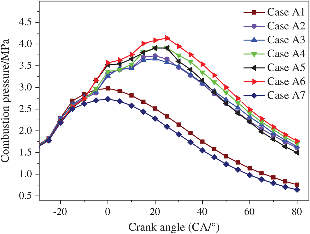
Figure 15: Cylinder pressure change curve
4.3.2 Influence of Fuel Injection Timing Parameters on Combustion Characteristics
As shown in Figs. 15 and 16, for CaseA6, the highest combustion pressure was 4.14 MPa at 25°ATDC. Since the burned mass fraction at the time corresponding to the highest combustion pressure was an important parameter of the combustion speed in the reaction cylinder [37], which at this time was at the 25°ATDC, the burned mass fraction was 44%, indicating that the burning speed was relatively high. CaseA5 reached the maximum combustion pressure of 3.91 MPa at 20°ATDC, CaseA4 reached the maximum combustion pressure of 3.91 MPa at 25°ATDC, and CaseA2 and CaseA3 reached 3.73 MPa and 3.66 MPa at 20°ATDC. The phase of the eccentric shaft corresponding to the maximum combustion pressure was in good agreement with the relevant test data of the rotary engine. For CaseA1 and CaseA7, the maximum combustion pressure value appeared at the top dead center (TDC), the maximum combustion pressure was smaller, and the combustion effect was poor.

Figure 16: Change diagram of fuel mass fraction
In the initial stage of the combustion, the pressure growth rate of CaseA5 and CaseA6 increased significantly, while the pressure growth rate of CaseA2, CaseA3 and CaseA4 were relatively small. At the time of the top dead center, the pressure values of CaseA5 and CaseA6 were obviously greater than the pressure values in other cases. In response to this phenomenon, combined with the fuel distribution law in Fig. 14 for CaseA2, CaseA3 and CaseA4 at 20°BTDC, the fuel in the cylinder had two concentrated distribution areas, and the two fuel distribution areas were mutually concentrated. Partitioning was not conducive for the spread of flame and the initial combustion process. In CaseA5 and CaseA6, the fuel was not concentrated in two areas, but in the cylinder as a whole, presented a continuous and even distribution. Compared to CaseA5, the fuel distribution in the front of the combustion chamber in CaseA6 was more uniform. Therefore, a more continuous and uniform fuel distribution law was not only beneficial to the initial flame propagation, but also to the space matching effect of the fuel distribution at this time, and the front and rear dual spark plug ignition scheme, which in turn improved the initial combustion process, resulting in a significant increase in combustion pressure.
After the top dead center, as the combustion process continued, the pressure values in CaseA4, CaseA5, and CaseA6 were significantly greater than those in CaseA2 and CaseA3. It can be seen from the Fig. 17 that in CaseA4 and CaseA6, the pressure growth rate increased from small, and the combustion pressure reached the maximum, while in CaseA5, the pressure growth rate changed less and the pressure growth was relatively slow. For CaseA5, although the pressure growth rate was relatively large before the top dead center, the pressure growth was obviously slower after the top dead center. It can be seen from Fig. 16 that at the time of top dead center, the burned mass fraction of fuel in CaseA5 was the largest, and at 20°ATDC, the burned mass fraction of CaseA6 was the largest. The burned mass fraction of CaseA5 was significantly lower than CaseA6, indicating that in the TDC to 20°ATDC stage, compared with CaseA5, there was more fuel in CaseA6 to complete the combustion process in this stage, and it was at the beginning of the expansion stroke. The inner space being smaller, and more fuel being burned in this stage is of great significance for improving the power of the rotary engine, which caused the combustion pressure in CaseA6 to increase at the fastest rate in this stage. At 40°ATDC and 60°ATDC, the burned mass fraction of CaseA6 maintained its maximum value. Compared with CaseA4 and CaseA3, the burned mass fraction of CaseA5 increased most slowly to further reveal the difference between CaseA6 and CaseA5. The big reason is the action mechanism of the flow field in the cylinder and the flame propagation process. Fig. 17 shows the distribution law of the flow field and CH2O in the cylinder at 60°ATDC.
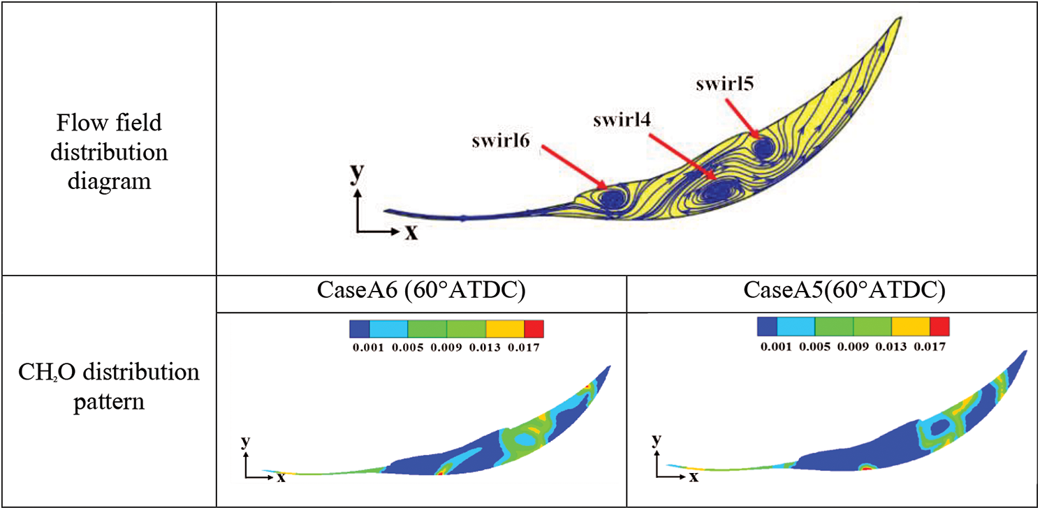
Figure 17: 60°ATDC Flow field and CH2O distribution pattern
According to the flow field distribution diagram in Fig. 17, as the expansion process continued, at the time of 60°ATDC, the flow field in the cylinder presented a flow field distribution law dominated by swirl4, swirl5 and swirl6. It can be seen from the analysis of Fig. 17 that, compared to CaseA5, the distribution area of CH2O in CaseA6 had been significantly enlarged, and further compared to the flow field distribution pattern, it was found that the concentrated distribution area of CH2O was exactly in the vicinity of swirl4. From the previous analysis, it can be seen that the expansion vortex will be generated during the expansion process under the condition of the dual-pit combustion chamber. The existence of the vortex significantly accelerated the mixing process of diesel and air [38–40], thereby effectively increasing the diffusion combustion speed. The CH2O distribution area in CaseA6 was larger, indicating that the vortex in CaseA6 promoted the mixing of fuel and air more significantly, which further promoted flame propagation and the combustion speed, resulting in a significantly higher fuel mass fraction in CaseA6 than in CaseA5.
In summary, when the fuel injection timing was 105°BTDC in the middle of the compression phase, the matching effect of fuel distribution and ignition scheme was best under the action of fuel spray in the cylinder and swirl motion in the flow field. The expansion vortex in the expansion process significantly promoted the mixing of fuel and air, accelerated the diffusion combustion speed, made the pressure peak highest and the power performance was the best.
4.3.3 Impact of Fuel Injection Timing Parameters on Main Emissions
In order to study the influence of fuel injection timing parameters on the emission level, based on the previous analysis of fuel distribution and combustion process, the case with the highest combustion pressure significant increase was selected to analyze the relevant emission level. Therefore, the late compression injection was selected. CaseA3 and CaseA4 for oil, CaseA5 and CaseA6 for compressed mid-term injection, were used for comparative analysis of emissions.
As shown in Fig. 18, at the time of 180°ATDC, the mass fraction of NO in CaseA5 was the largest as compared to other cases, the mass fraction of NO in CaseA6 was larger than in CaseA3 and CaseA4. It can be seen from Fig. 19 that the temperature in the cylinder started at 20°BTDC and increased sharply, then decreased slowly after reaching the maximum temperature, and the temperature reached a steady state at 170°ATDC.
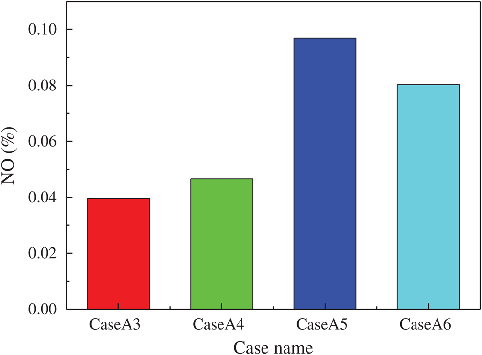
Figure 18: NOX mass fraction in cylinder 180°ATDC
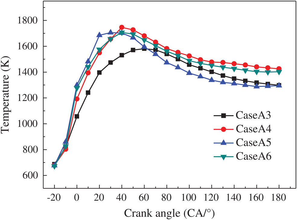
Figure 19: Curve of temperature change in cylinder
After ignition, because the temperature in CaseA5 increased at the fastest rate, the temperature in CaseA5 obviously maintained the maximum value before 30°ATDC, and reached the maximum temperature at 30°ATDC. The production of NO was mainly affected by temperature and oxygen concentration. At this time, the oxygen in the cylinder was relatively sufficient. Therefore, it was the conditions of high temperature and relatively sufficient oxygen in the cylinder at this time that made the NO production larger. For CaseA6, the temperature curve in the early stage had a larger growth rate, and the growth rate was later reduced compared to CaseA5, the phase corresponding to the highest temperature was relatively lagging. At this time, the oxygen concentration decreased due to the consumption of the combustion process, resulting in a decrease in the final NO production. In addition, although the maximum temperature in the cylinder reached the maximum value of 1746 K in CaseA4, the temperature in the early stage was further reduced compared to CaseA5, and the later stage was restricted by the decrease in oxygen concentration, resulting in less NO production. Before 60°ATDC in CaseA3, the temperature value was kept at the minimum, and the highest temperature corresponded to the most lagging phase, resulting in the suppression of NO production. As a result, the amount of NO produced was significantly the least.
As shown in Fig. 20, at the time of 180°ATDC, the amount of soot generated in CaseA4 was the largest, and in CaseA6, CaseA5 and CaseA3, the amount of soot generated slightly decreased in turn. When combined with the analysis of Figs. 19 and 20, it was found that the relationship between the amount of soot generated and the temperature in the cylinder in the early stage was not obvious. This was because the generation of soot was not only related to temperature, but also related to the distribution of the mixture in the cylinder and the oxygen residence time.
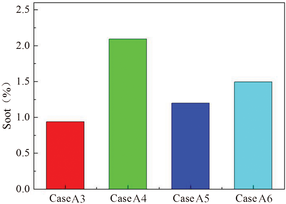
Figure 20: Soot mass fraction diagram in cylinder 180°ATDC
In summary, the changes in NO emissions and injection timing parameters were more sensitive. When the injection timing was 75°BTDC and 85°BTDC in the late compression stage, the NO mass fraction remained at a low level, and the NO mass fraction at the injection timing was in the mid-compression period. The score was higher, and the correlation between soot generation and fuel injection timing changes was weak. When the fuel injection timing was 85°BTDC, the soot generation volume remained at a relatively high level. Therefore, considering the NO and soot emission levels, the emission performance is the best when the injection timing is 75°BTDC.
Targeting the problem of difficulty in propagating the flame in the cylinder of the rotary engine to the rear, this paper adopts a scheme that combines the improvement of the flow field distribution in the cylinder of the rotary engine with the optimization of the spray characteristic parameters. The aim is to optimize the flow field distribution and reveal the interaction between flow and combustion in diesel rotary engines to improve the combustion and emission characteristics of rotary engines. The main results obtained are as follows:
1. Complete the design of the dual-pit combustion chamber structure and its comparison with the traditional combustion chamber structure. Focus on the changes in the flow field distribution in the cylinder during the compression process and its impact on the combustion process during the expansion process.
2. In terms of flow field, during the entire compression stroke, with the gradual reduction of the space in the cylinder, eddy currents are generated and developed, and finally broken into unidirectional flow. During the entire compression process, compared with the traditional combustion chamber, the presence of the front guide wall and the rear guide wall in the double-pit combustor significantly increases the vortex intensity of the central vortex and increases the overall air velocity in the cylinder, thereby Further strengthen the overall vortex strength in the cylinder.
3. In terms of combustion characteristics, during the expansion process, the front guide wall and rear guide wall in the double-pit combustor continue to act on the flow field in the cylinder, resulting in a middle expansion vortex, a front expansion vortex and a rear expansion vortex. The coexisting flow field distribution law effectively strengthens the intensity of air movement in the cylinder. Under the action of strong expansion vortex, it effectively promotes the mixing process of oil and gas in the cylinder, thereby significantly increasing the diffusion combustion speed after top dead center, improving the combustion constant volume, and finally leading to the peak pressure in the cylinder of the rotary engine It further increased significantly by 8.6%, reaching 3.66 MPa.
4. Based on the optimization of the flow field distribution law, the influence of the injection timing parameters on the fuel distribution, combustion and emission characteristics is studied. The research results show that: In the middle of compression, the fuel in the cylinder is concentrated in the front and the back area. In the later stage of compression, the fuel is injected more evenly from front to back in the cylinder. When the fuel injection timing is 105°BTDC in the middle of the compression phase, the fuel distribution law matches the ignition scheme best, the maximum combustion pressure in the cylinder reaches 4.14 MPa, and the power performance is further improved significantly. In terms of emissions, changes in NO emissions and fuel injection timing parameters are more sensitive. When the injection timing is 75°BTDC and 85°BTDC in the later stage of compression, the mass fraction of NO remains at a low level, while the correlation between soot generation and the change of injection timing is weak. When the injection timing is 85°BTDC, soot generation keep it at a relatively high level.
Funding Statement: This work was supported by National Natural Science Foundation of China No. 51976083 and the Qing Lan Project.
Conflicts of Interest: The authors declare that they have no conflicts of interest to report regarding the present study.
1. Otchere, P., Pan, J., Fan, B., Chen, W., Lu, Y. et al. (2020). Mixture formation and combustion process of a biodiesel fueled direct injection rotary engine (DIRE) considering injection timing, spark timing and equivalence ratio-CFD study. Energy Conversion and Management, 217, 112948. DOI 10.1016/j.enconman.2020.112948. [Google Scholar] [CrossRef]
2. Amrouche, F., Erickson, P. A., Park, J. W., Varnhagen, S. (2016). Extending the lean operation limit of a gasoline Wankel rotary engine using hydrogen enrichment. International Journal of Hydrogen Energy, 41(32), 14261–14271. DOI 10.1016/j.ijhydene.2016.06.250. [Google Scholar] [CrossRef]
3. Gao, J., Tian, G., Sorniotti, A., Ece, K., Palo, R. D. (2019). Review of thermal management of catalytic converters to decrease engine emissions during cold start and warm up. Applied Thermal Engineering, 147, 177–187. DOI 10.1016/j.applthermaleng.2018.10.037. [Google Scholar] [CrossRef]
4. Gao, J., Tian, G., Jenner, P., Burgess, M. (2020). Intake characteristics and pumping loss in the intake stroke of a novel small scale opposed rotary piston engine. Journal of Cleaner Production, 261, 121180. DOI 10.1016/j.jclepro.2020.121180. [Google Scholar] [CrossRef]
5. Gao, J., Tian, G., Ma, C., Balasubramanian, D., Xing, S. et al. (2020). Numerical investigations of combustion and emissions characteristics of a novel small scale opposed rotary piston engine fuelled with hydrogen at wide open throttle and stoichiometric conditions. Energy Conversion and Management, 221, 113178. DOI 10.1016/j.enconman.2020.113178. [Google Scholar] [CrossRef]
6. Abraham, J., Bracco, F. V. (1989). Comparisons of computed and measured pressure in a premixed-charge natural-gas-fueled rotary engine. Society of Automotive Engineers, 890671, Detroit, USA. [Google Scholar]
7. Abraham, J., Bracco, F. V. (1991). 3-D computation of premixed-charge natural gas combustion in rotary engines. Society of Automotive Engineers, 910625, Sacramento, USA. [Google Scholar]
8. Li, L., Yin, Z., Qiao, W., Liu, Z., Hu, Y. (2005). Study on mathematical combustion model for a gasoline rotary combustion engine. Transactions of CSICE, 23(5), 457–461. [Google Scholar]
9. Zhou, N., Chen, Q., Pei, H., Gao, H. (2008). Rotary combustion engine performance influenced by the direction of fuel injection. Internal Combustion Engines, (2), 16–18. [Google Scholar]
10. Fan, B., Pan, J., Liu, Y., Zhu, Y. (2015). Effects of ignition parameters on combustion process of a rotary engine fueled with natural gas. Energy Conversion and Management, 103, 218–234. DOI 10.1016/j.enconman.2015.06.055. [Google Scholar] [CrossRef]
11. Fan, B., Pan, J., Huang, J., Xiao, M., Yao, J. (2015). Effect of combustion chamber structure on combustion process of natural gas rotary engine. Chinese Journal of Mechanical Engineering, 51(22), 141–151. [Google Scholar]
12. Karatsu, Y., Minota, S., Hashimoto, H., Moriue, O., Murase, E. et al. (2015). Simultaneous observation of combustion in optical rotary engine by bottom view and side view. SAE Technical Paper, 19. [Google Scholar]
13. Hamady, F., Kosterman, J., Chouinard, E., Somerton, C., Schock, H. et al. (1989). Stratified charge rotary engine internal flow studies at the MSU Engine Research Laboratory. Technical Paper, Automotive Sector. [Google Scholar]
14. Morita, T., Hamady, F., Stuecken, T., Somerton, C., Schockl, H. (1991). Fuel-air mixing visualization in a motored rotary engine assembly. SAE Technical Paper, 21. [Google Scholar]
15. Hasegawa, Y., Yamaguchi, K. (1993). An experimental investigation on air-fuel mixture formation inside a low-pressure direct injection stratified charge rotary engine. SAE Technical Paper, 22. [Google Scholar]
16. Votaw, Z. S. (2012). Computational Study on Micro-Pilot Flame Ignition Strategy for a Direct Injection Stratified Charge Rotary Engine, 41. [Google Scholar]
17. Shimizu, R., Yamada, M., Sakai, T., Uchiyama, J. (2016). Rotary piston engine mounted on vehicle: U.S. Patent Application 14/825,035. 2016-3-24.27. [Google Scholar]
18. Picard, M., Tian, T., Nishino, T. (2016). Predicting gas leakage in the rotary engine—Part I: Apex and corner seals. Journal of Engineering for Gas Turbines and Power, 138(6), 062503.28. [Google Scholar]
19. Alrbai, M., Qawasmeh, B., Al-dahidi, S., Ayadi, O. (2020). Influence of hydrogen as a fuel additive on combustion and emissions characteristics. Thermal Science, 24, 71. [Google Scholar]
20. Ji, C., Su, T., Wang, S., Zhang, B., Yu, M. et al. (2016). Effect of hydrogen addition on combustion and emissions performance of a gasoline rotary engine at part load and stoichiometric conditions. Energy Conversion and Management, 121, 272–280. [Google Scholar]
21. Fan, B., Pan, J., Yang, W., An, H., Tang, A. et al. (2015). Effects of different parameters on the flow field of peripheral ported rotary engines. Engineering Applications of Computational Fluid Mechanics, 9(1), 445–457. [Google Scholar]
22. Fan, B., Pan, J., Yang, W., Zhu, Y., Chen, W. (2016). Effects of hydrogen blending mode on combustion process of a rotary engine fueled with natural gas/hydrogen blends. International Journal of Hydrogen Energy, 41(6), 4039–4053. [Google Scholar]
23. Gao, J., Tian, G., Sorniotti, A., Ece Karci, A., Di Palo, R., Palo, Di. (2019). Review of thermal management of catalytic converters to decrease engine emissions during cold start and warm up. Applied Thermal Engineering, 147, 177–187. [Google Scholar]
24. Nguyen, H. L., Addy, H. E., Bond, T. H., Lee, C. M., Chun, K. S. (1987). Performance and efficiency evaluation and heat release study of a direct-injection stratified-charge rotary engine. SAE Technical Paper. [Google Scholar]
25. Shih, T. I. P., Schock, H. J., Nguyen, H. L., Stegeman, J. D. (1987). Numerical simulation of the flow field in a motored two-dimensional Wankel engine. Journal of Propulsion and Power, 3(3), 269–276. [Google Scholar]
26. Jeong, U. Y., Koh, H. M., Lee, H. S. (2002). Finite element formulation for the analysis of turbulent wind flow passing bluff structures using the RNG k-ε model. Journal of Wind Engineering and Industrial Aerodynamics, 90(3), 151–169. [Google Scholar]
27. Fan, B., Pan, J., Tang, A., Pan, Z. Zhu, Y. et al. (2015). Experimental and numerical investigation of the fluid flow in a side-ported rotary engine. Energy Conversion and Management, 95, 385–397. DOI 10.1016/j.enconman.2015.02.047. [Google Scholar] [CrossRef]
28. Zhu, H., Lin, Y., Xie, L. (2010). FLUENT fluid analysis and simulation practical course. Beijing: People’s Posts and Telecommunications Press. [Google Scholar]
29. Gärtner, U., Hohenberg, G., Daudel, H., Oelschlegel, H. (2004). Development and application of a semi-empirical NOx model to various HD diesel engines. In: Gärtner, U., Hohenberg, G., Daudel, H., Oelschlegel, H. (eds.Thermo-and fluid dynamic processes in diesel engines, vol. 2, pp. 285–312.65U. Berlin Heidelberg: Springer. [Google Scholar]
30. Chen, W., Pan, J., Fan, B., Liu, Y., Peter, O. (2017). Effect of injection strategy on fuel-air mixing and combustion process in a direct injection diesel rotary engine (DI-DRE). Energy Conversion and Management, 154, 68–80. DOI 10.1016/j.enconman.2017.10.048. [Google Scholar] [CrossRef]
31. Amrouche, F., Erickson, P. A., Varnhagen, S., Park, J. W. (2016). An experimental study of a hydrogen-enriched ethanol fueled Wankel rotary engine at ultra lean and full load conditions. Energy Conversion and Management, 123, 174–184. DOI 10.1016/j.enconman.2016.06.034. [Google Scholar] [CrossRef]
32. Patel, A., Kong, S. C., Ritz, R. D. (2004). Development and validation of a reduced reaction mechanism for HCCI engine simulations. SAE Technical Paper. [Google Scholar]
33. Zhou, L., Liu, X., Gao, Z. (2004). Internal Combustion Engine. 70. [Google Scholar]
34. Su, T., Ji, C., Wang, S., Shi, L. Yang, J. et al. (2017). Improving idle performance of a hydrogen-gasoline rotary engine at stoichiometric condition. International Journal of Hydrogen Energy, 42(16), 11893–11901. DOI 10.1016/j.ijhydene.2017.01.220. [Google Scholar] [CrossRef]
35. Liu, F., Su, L., Li, X., He, X. (2015). Experimental research on the diffusion flame formation and combustion performance of forced swirl combustion system for DI diesel engines. Energy Conversion and Management, 106, 826–834.73. [Google Scholar]
36. Fan, B., Pan, J., Liu, Y., Zhu, Y., Pan, Z. et al. (2018). Effect of hydrogen injection strategies on mixture formation and combustion process in a hydrogen direct in-jection plus natural gas port injection rotary engine. Energy Conversion and Management, 160, 150–164. [Google Scholar]
37. Fan, B., Pan, J., Yang, W., Pan, Z., Bani, S. et al. (2017). Combined effect of injection timing and injection angle on mixture formation and combustion process in a direct injection (DI) natural gas rotary engine. Energy, 128, 519–530. DOI 10.1016/j.energy.2017.04.052. [Google Scholar] [CrossRef]
38. Fan, B., Pan, J., Yang, W., Liu, Y., Bani, S. et al. (2017). Numerical investigation of the effect of injection strategy on mixture formation and combustion process in a port in-jection natural gas rotary engine. Energy Conversion Management, 133, 511–523. [Google Scholar]
39. Patel, A., Kong, S. C., Reitz, R. D. (2004). Development and validation of a reduced reaction mechanism for HCCI engine simulations. SAE Technical Paper, 63. [Google Scholar]
40. Fan, B., Pan, J., Pan, Z., Tang, A., Zhu, Y. et al. (2015). Effects of pocket shape and ignition slot locations on the combustion processes of a rotary engine fueled with natural gas. Applied Thermal Engineering, 89, 11–27. DOI 10.1016/j.applthermaleng.2015.05.078. [Google Scholar] [CrossRef]
 | This work is licensed under a Creative Commons Attribution 4.0 International License, which permits unrestricted use, distribution, and reproduction in any medium, provided the original work is properly cited. |