| Energy Engineering |
DOI: 10.32604/EE.2021.014482
ARTICLE
Position Sensorless Control System of Permanent Magnet Synchronous Linear Motor Based on Sliding Mode Observer with an Improved Phase-Locked Loop
1Department of Mechanical and Electrical Engineering, Suqian College, Suqian, 223800, China
2School of Electrical Engineering, Nantong University, Nantong, 226019, China
*Correspondence Author: Feng Yu. Email: yufeng628@ntu.edu.cn
Received: 30 September 2020; Accepted: 16 November 2020
Abstract: In this paper, position sensorless control system of permanent magnet synchronous linear motor (PMSLM) based on sliding mode observer (SMO) with an improved phase-locked loop (PLL) is studied. Firstly, according to the mathematical model, a SMO is designed for sensorless control PMSLM drive. Thereafter, an improved PLL is proposed to tackle the imperfection of data overflow existed in the traditional PLL. The designed SMO incorporating with the improved PLL can be effectively suppress the pulsation of the estimated position and hence the chattering of the derived electrical angular velocity. At last, simulated and experimental results are presented to verify the effectiveness and feasibility of the position sensorless control system.
Keywords: Position sensorless; PMSLM; SMO; PLL
Permanent magnet synchronous linear motor (PMSLM) has attracted wide attention due to its simple structure, small size, high positioning accuracy and greater overload capacity. In addition, compared to traditional PMSM drive system, PMSLM drive system performs higher efficiency since it can directly achieve linear mechanical motion without using intermediate transmission. Therefore, it has been actively developed in high-precision machine tools, automation control systems and robotics [1–4].
With regard to PMSLM drive, the real-time position of mover is generally required, which can be obtained using a costly position sensor. However, in some special applications, mounting the position sensor is not feasible, which is resulted from the susceptibility of position sensor to high temperature, vibration, as well as humidity installation accuracy. As such, sensorless control techniques have gained ever-growing concern, including flux observation method [5], position detection method based on high frequency signal injection [6–9], fuzzy adaptive method [10–12], and nonlinear observer-based position/speed estimation method [13–15].
Among various nonlinear observers, sliding mode observer (SMO) is highly favorable for sensorless control of PMSLM drive due to its desired dynamic response and strong anti-jamming capability [16–20]. Nevertheless, caused by the limited capacity of digital processor, the obtained mover position/speed inevitably performs pulsation, degrading the control performance to some extent. In general, there are two solutions to acquire smooth estimated signal of speed. On the one hand, low-pass filter can be used to suppress high-order harmonics of the estimated position signal, and then smooth speed can be obtained by means of differential operation. However, the use of low-pass filter will lead to a non-negligible delay of the system response. On the other hand, phase-locked loop (PLL) scheme is effective to settle the cumulative error of estimated speed. In this scheme, a closed position angle loop is constructed to further correct the estimated speed, where the estimated position angle is the reference and a feed-back position angle obtained from estimated signal of speed is introduced. Nevertheless, the use of traditional PLL could result in the issue of data overflow. Since the introduced feed-back position angle is obtained by integral operation of the estimated speed, a large chattering of the estimated speed would cause the data overflow of the feed-back position angle, especially at the start-up stage. Thus, an additional control algorithm is usually desired to assist in starting [20].
In this paper, PMSLM drive using position sensorless control method based on SMO is studied. In particular, to tackle the imperfection of data overflow existed in tradition PLL, an improved PLL scheme with a novel structure is developed. Comprehensive simulated and experimental results are presented to verify the effectiveness of the proposed algorithm.
In the dq coordinate, the flux and voltage equations of PMSLM drive can be constructed as
where ψd and ψq are dq-axes fluxes; ud and uq are dq-axes voltages; id and iq are dq-axes currents; Ld is direct-axis inductance and Lq is quadrature-axis inductance; Rs is stator armature winding resistance; ψpm is permanent magnet flux amplitude; electrical angular speed ωe = πv/τ, v is the mover speed and τ is the pole pitch.
In addition, PMSLM electromagnetic force Fe can be expressed as
In order to facilitate the establishment of PMSLM flux observer and the magnetic pole position estimation model, the PMSLM voltage and flux mathematical model under dq coordinate system is transformed to αβ coordinate system by 2r/2s transformation, as
where ψα and ψβ are αβ-axes fluxes; uα and uβ are αβ-axes voltages; iα and iβ are αβ-axes currents; θe is the electrical angle; two variables inductors [L1 L2] = [(Ld + Lq)/2 (Ld − Lq)/2].
Surface mounted PMSLM is of concern, in which manner, direct-axis inductance Ld and quadrature-axis inductance Lq are approximately equal. Then L2 ≈ 0, (5) can be simplified to
Substituting Eq. (6) into Eq. (4), it can be obtained as
with
where eα and eβ are the αβ-axes components of back-EMF.
3.1 Design of Sliding Mode Observer
Based on the mathematical model of PMSLM, SMO can be established to estimate the position of the mover. In principle, the SMO is designed in accordance with the errors between sensed and estimated currents. Then, using the mentioned current errors along with the outputs of SMO, the back-EMF of the motor could be obtained. Thereafter, speed and position can be estimated on the basis of the back-EMF.
According to (7), the stator current state equation can be derived as
In order to construct a SMO, the estimated current is defined as
Then, the sliding surface is selected as
Typically, the sliding mode observer can be designed [16,17] as
with
where zα and zβ are the switching functions and k is a constant. In general, the value of k should be properly selected to compromise between the stability and convergence speed of SMO. In this paper, the following adaptive law is employed for the determination of k, as
where
Comparing (9) and (12), it can be confirmed that, when the estimated currents are identical with the sensed currents, zα and zβ are in essence equivalent to the back-EMF. While, zα and zβ perform the high frequency pulse forms due to the switching feature as shown in (13). Therefore, by the use of low-pass filter, the back-EMF
where ωc is the cut-off frequency of the low pass filter. Then, according to estimated back-EMF, the electrical angle
Besides, a compensation of the phase delay resulted from the use of low-pass filter is required. For the low-pass filter with the cut-off frequency of ωc, the phase delay Δθ can be calculated by
As a result, the further estimated position angle can be obtained as
When the position angle is estimated, the electrical angular velocity can be easily derived by differential operation. Nevertheless, due to the limited capacity of digital processor, the pulsation is inevitably existed in the estimated position angle, in turn resulting in the chattering of the derived electrical angular velocity. To avoid this phenomenon, low-pass filter can be applied to further smooth the estimated position angle and hence the electrical angular velocity, whereas it further causes a non-negligible delay of the system response.
Another way is the use of PLL. In principle, the purpose of this scheme is to construct a closed position angle loop for the sake of further correction for the estimated speed. An additional position angle obtained from estimated signal of speed is introduced to function as the feed-back value of the closed loop, while the estimated position angle from SMO serves as the reference. By the closed loop, the pulsation of the estimated position angle and hence the chattering of the derived electrical angular velocity can be effectively suppressed.
The imperfection of the traditional PLL is data overflow. Typically, the estimated position angle from SMO is in the range of [0, 2π], while the feed-back position angle is obtained by means of integral operation of estimated speed, and is normally in the range of [0, oo). In this manner, if a large chattering of the estimated electrical angular velocity occurs (especially at the start-up stage), the data overflow of the additional position angle will be resulted, namely exceeding the range of [0, 2π].

Figure 1: Principle of traditional process of accumulating operation
One approach is to further process the estimated position using accumulating operation, as shown in Fig. 1, where
In order to solve this problem, an improved PLL is proposed in this paper, as presented in Fig. 2. Both the estimated and feedback position respectively modulo 2π to ensure the feedback one within the range of [0, 2π]. The principle is shown in Fig. 3, where

Figure 2: Structure of improved phase locked loop (PLL)

Figure 3: Principle of improved process
3.3 Sensorless Vector Control System
Fig. 4 shows the block diagram of PMSLM sensorless control system based on flux observer. The following steps are required.
Step 1. Transform the sensed currents and voltages on the abc frame into the αβ frame by Clark transformation;
Step 2. Estimate the position angle and hence the speed of the mover by means of SMO;
Step 3. Calculate d- and q-axes currents from currents on the αβ frame using Park transformation;
Step 4. Acquire the reference of q-axis current applying the outer speed controller and the reference of d-axis current is set to 0 to implement id = 0 control scheme;
Step 5. Obtain the commands of α- and β-axes voltages, synthesize the reference voltage using SVPWM, then output the corresponding PWM signals to inverter.
In order to verify the validity of position sensorless control system of PMSLM based on SMO, the traditional and improved phase-locked loop algorithms are simulated in Matlab/Simulink. Main parameters of PMSLM are shown in Tab. 1. The initial load torque is set as 200 N and changed to 500 N at 0.3 s. In addition, DC voltage is 500 V, given motor speed is 2 m/s and PWM frequency is set as 10 kHz.

Figure 4: Block diagram of permanent magnet synchronous linear motor (PMSLM) sensorless control system based on sliding mode observer (SMO)
Three-phase armature current, dq-axes currents and the electromagnetic force waveform under abrupt change of load are shown in Figs. 5–7, respectively. As seen in Fig. 5, three-phase sinusoidal currents can be obtained. Under pre- and post-step-change conditions, the peak values of currents are 2A and 5A, respectively, which are consistent with the value of q-axis current shown in Fig. 6. In addition, d-axis current maintains the value of 0A, ensuring minimized copper loss of the drive system. Moreover, the electromagnetic torque can immediately track the load command, as presented in Fig. 7.
The estimation of the pole position is evaluated and presented in Figs. 8 and 9. From Fig. 8, it is confirmed that the estimated position (theta-est) can perfectly track the actual position (theta-real) with a negligible tracking error, regardless of the load change. Meanwhile, since the fact that the waveform of estimated position in essence oscillates along that of the actual position, some spikes with the amplitude of 2π or −2π occur when the actual position passes through the peak value (2π), as depicted in Fig. 9. Overall, by using SMO in conjunction with the improved PLL, a precise position observation can be obtained, resulting in the outstanding performance of the system.
Table 1: Main parameters of the tested PMSLM


Figure 5: Waveform of three phase armature currents. (a) Before enlargement; (b) amplified

Figure 6: Waveform of d-q axes currents

Figure 7: Waveform of electromagnetic thrust
In order to verify the effectiveness and feasibility of the improved PLL in terms of velocity estimation, Figs. 10 and 11 present the results obtained by traditional PLL and the proposed one, respectively. It is obvious that using both methods, the estimated velocity can track the actual one quickly. In addition, as seen in Fig. 10b, by virtue of the traditional PLL, the error between the actual and the estimated velocities ranges from −1.5 to 1.7 (m/s). Comparatively, the proposed PLL allows the resulting error within the range of −0.4 to 1 (m/s), as presented in Fig. 11b. In particular, at the start-up stage, serious bias of the estimated velocity with respect to the actual velocity can be observed when the traditional PLL is employed, while a considerable improvement can be obtained by applying the proposed PLL. In comparison, the proposed PLL performs a considerably better performance than the traditional PLL.
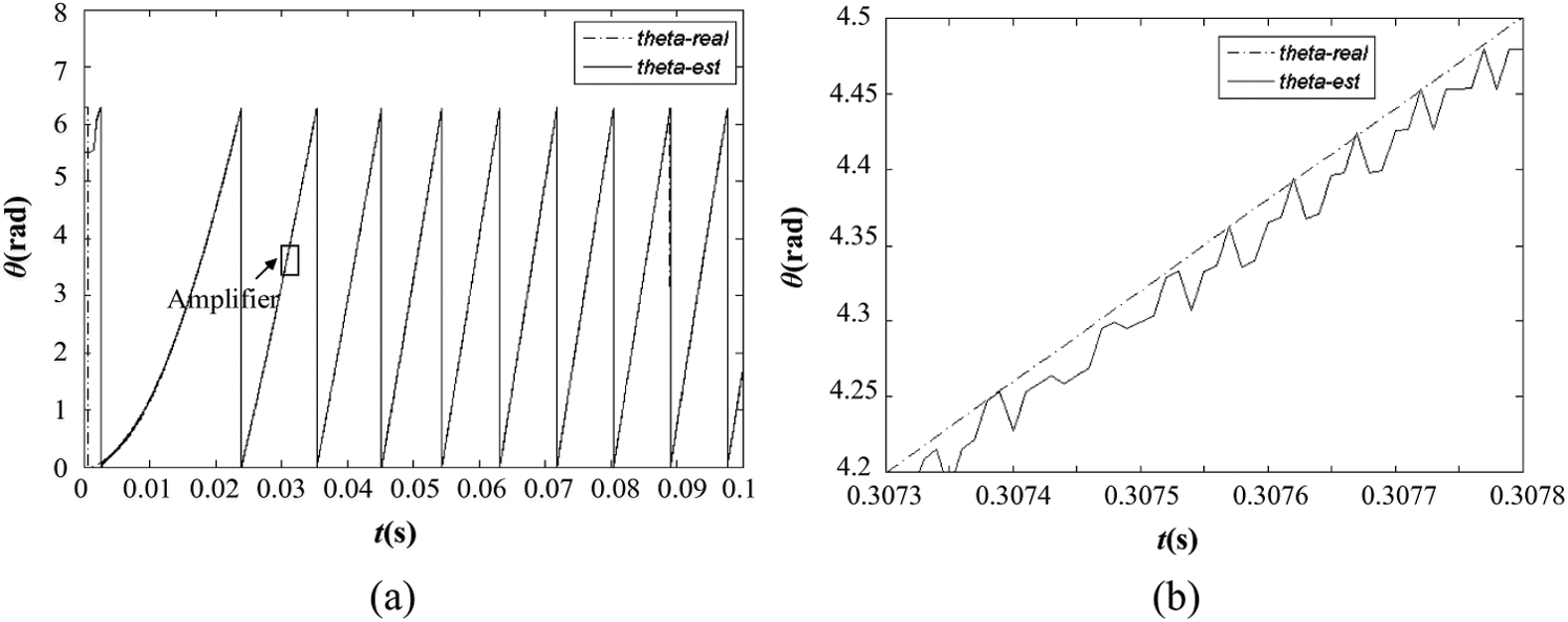
Figure 8: Waveform of estimated and actual position angles. (a) Before enlargement; (b) amplified

Figure 9: Waveform of error between estimated and actual position angles

Figure 10: Velocity estimation by traditional PLL. (a) actual and estimated velocities; (b) velocity error

Figure 11: Velocity estimation by improved PLL. (a) Actual and estimated velocities; (b) velocity error

Figure 12: Experiment rig. (a) Hardware control system; (b) PMSLM
The experimental investigation is conducted to test the effectiveness of position sensorless control system of PMSLM based on SMO, as presented in Fig. 12. The Hardware control system is shown in Fig. 12a. The power inverter consists of three Infineon FF300R12ME4 modules. Furthermore, the machine’s stator currents and phase voltages are sampled by CAS6-NP and LV25-P from LEM, and then fed into a digital signal processor TMS320F28335, which is produced by TI. The real-time control code implemented in TMS320F28335 is developed with C language in the Code Composer Studio 6.0. The PWM frequency is set as 10 kHz, whereas the designed SMO is carried out with a frequency of 20 kHz. In particular, the actual magnetic pole position is sensed by using WTB1-0550-MM and extensively used for comparison with the estimated position. In addition, the PMSLM drive system is seen in Fig. 12b. By means of pulleys, a PMSLM is connected to some weights that serve as the load. The parameters of tested motor are the same as that in simulation.
The experimental results under the rated condition (mover velocity command of 2 m/s and load torque of 500 N·m) are shown in Figs. 13–15. As expected, three-phase sinusoidal currents are generated as presented in Fig. 13. Meanwhile, the actual pole position along with the estimated one is given in Fig. 14. It can be confirmed that the estimated position is entirely equal to the actual one, except the superimposed high frequency pulsation with an affordable amplitude. Similar pulsation exists in the estimated velocity shown in Fig. 15 as well. As aforementioned, the cause is limited capacity of the processor, and SMO is conducted with a frequency of 20 kHz in the experiment. Actually with the increase of this execution frequency, the amplitude of superimposed pulsation will decrease, accompanied with higher pulsation frequency.
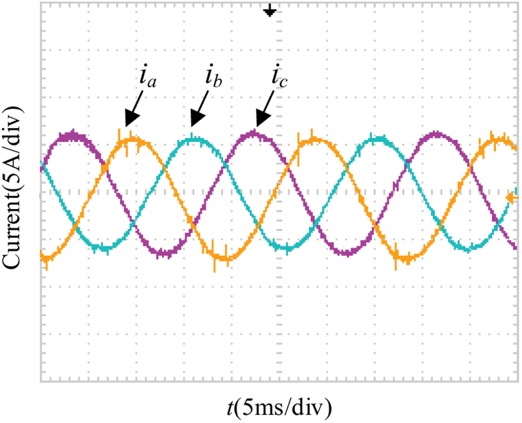
Figure 13: Experimental waveforms of three-phase armature current

Figure 14: Actual and estimated position angles

Figure 15: Actual and estimated velocities
In this paper, the position sensorless control system of PMSLM based on SMO is studied, and an improved PLL is proposed to tackle the imperfection of data overflow existed in the traditional scheme. A SMO is designed according to the mathematical model of PMSLM drive to achieve the position sensorless control, and the steps of the PMSLM position sensorless control are presented in detail. Simulation and experiment are conducted, and the results verify the effectiveness and feasibility of the proposed PLL. In particular, by the proposed PLL, the error between the estimated and the actual velocities can be significantly reduced even at the start-up stage.
Funding Statement: Suqian Sci & Tech Program, Grant No. H201921; Top-notch Academic Programs Project of Jiangsu Higher Education Institutions, Grant No. PPZY2015C252.
Conflicts of Interest: The authors declare that they have no conflicts of interest to report regarding the present study.
1. Taniguchi, S., Mochiduki, S., Yamakawa, T. (2016). Starting procedure of rotational sensorless PMSM in the rotating condition. IEEE Transactions on Industry Applications, 45(1), 194–202. DOI 10.1109/TIA.2008.2009496. [Google Scholar] [CrossRef]
2. Chaibet, A., Boukhnifer, M., Ouddah, N., Monmasson, E. (2020). Experimental sensorless control of switched reluctance motor for electrical powertrain system. Energies, 13(2), 3081. DOI 10.3390/en13123081. [Google Scholar] [CrossRef]
3. Bisheimer, G., Sonnaillon, M., Angelo, C. (2010). Full speed range permanent magnet synchronous motor control without mechanical sensors. IET Electric Power Applications, 4(1), 35–44. DOI 10.1049/iet-epa.2008.0187. [Google Scholar] [CrossRef]
4. Kim, J., Choi, S., Cho, K. (2016). Position estimation using linear hall sensors for permanent magnet linear motor systems. IEEE Transactions on Industrial Electronics, 63(12), 7644–7652. DOI 10.1109/TIE.2016.2591899. [Google Scholar] [CrossRef]
5. Andersson, A., Thiringer, T. (2018). Motion sensorless IPMSM control using linear moving horizon estimation with Luenberger observer state feedback. IEEE Transactions on Transportation Electrification, 4(2), 464–473. DOI 10.1109/TTE.2018.2790709. [Google Scholar] [CrossRef]
6. Cupertino, F., Pellegrino, G., Giangrande, P. (2011). Sensorless position control of permanent-magnet motors with pulsating current injection and compensation of motor end effects. IEEE Transactions on Industry Applications, 47(3), 1371–1379. DOI 10.1109/TIA.2011.2126542. [Google Scholar] [CrossRef]
7. Cupertino, F., Giangrande, P., Ellegrino, G. (2011). End effects in linear tubular motors and compensated position sensorless control based on pulsating voltage injection. IEEE Transactions on Industrial Electronics, 58(2), 494–502. DOI 10.1109/TIE.2010.2046577. [Google Scholar] [CrossRef]
8. Accetta, A., Cirrincione, M., Pucci, M. (2012). Sensorless control of PMSM fractional horsepower drives by signal injection and neural adaptive-band filtering. IEEE Transactions on Industrial Electronics, 59(3), 1355–1366. DOI 10.1109/TIE.2011.2167729. [Google Scholar] [CrossRef]
9. Wang, G., Liu, R., Zhao, N. (2019). Enhanced linear ADRC strategy for HF pulse voltage signal injection based sensorless IPMSM drives. IEEE Transactions on Power Electronics, 34(1), 514–525. DOI 10.1109/TPEL.2018.2814056. [Google Scholar] [CrossRef]
10. Raca, D., Garcia, P., Reigosa, D. (2010). Carrier-signal selection for sensorless control of PM synchronous machines at zero and very low speeds. IEEE Transactions on Industry Applications, 46(1), 167–178. DOI 10.1109/TIA.2009.2036551. [Google Scholar] [CrossRef]
11. Piippo, A., Hinkkanen, M., Luomi, J. (2008). Analysis of an adaptive observer for sensorless control of interior permanent magnet synchronous motors. IEEE Transactions on Industrial Electronics, 55(2), 570–576. DOI 10.1109/TIE.2007.911949. [Google Scholar] [CrossRef]
12. Farhan, A., Abdelrahem, M., Saleh, A., Shaltout, A., Kennel, R. (2020). Simplified sensorless current predictive control of synchronous reluctance motor using online parameter estimation. Energies, 13(2), 492. DOI 10.3390/en13020492. [Google Scholar] [CrossRef]
13. Lu, K., Vetuschi, M., Rasmussen, P. (2010). Determination of high-frequency d-and q-axis inductances for surface-mounted permanent magnet synchronous machines. IEEE Transactions on Instrumentation and Measurement, 59(9), 2376–2382. DOI 10.1109/TIM.2009.2034578. [Google Scholar] [CrossRef]
14. Boldea, I., Paicu, M., Andreescu, G. (2008). Active flux concept for motion-sensorless unified AC drives. IEEE Transactions on Power Electronics, 23(5), 2612–2618. DOI 10.1109/TPEL.2008.2002394. [Google Scholar] [CrossRef]
15. Mobarakeh, B., Tabar, F., Sargos, F. (2007). Back-EMF estimation based sensorless control of PMSM: Robustness with respect to measurement errors and inverter irregularities. IEEE Transactions on Industry Applications, 43(2), 485–494. DOI 10.1109/TIA.2006.889826. [Google Scholar] [CrossRef]
16. Bernardes, T., Montagner, V., Gründling, H. (2014). Discrete-time sliding mode observer for sensorless vector control of permanent magnet synchronous machine. IEEE Transactions on Industrial Electronics, 61(4), 1679–1691. DOI 10.1109/TIE.2013.2267700. [Google Scholar] [CrossRef]
17. Fan, Y., Zhang, L., Cheng, M. (2015). Sensorless SVPWM-FADTC of a new flux-modulated permanent magnet wheel motor based on a wide-speed sliding mode observer. IEEE Transactions on Industrial Electronics, 62(5), 3143–3153. DOI 10.1109/TIE.2014.2376879. [Google Scholar] [CrossRef]
18. Wang, H., Liu, Y., Ge, X. (2018). Sliding-mode observer-based speed-sensorless vector control of linear induction motor with a parallel secondary resistance online identification. IET Electric Power Applications, 12(8), 1215–1224. DOI 10.1049/iet-epa.2018.0049. [Google Scholar] [CrossRef]
19. Liang, D., Li, J., Qu, R. (2018). Adaptive second-order sliding-mode observer for PMSM sensorless control considering VSI nonlinearity. IEEE Transactions on Power Electronics, 33(10), 8994–9004. DOI 10.1109/TPEL.2017.2783920. [Google Scholar] [CrossRef]
20. Zhao, W., Jiao, S., Chen, Q. (2018). Sensorless control of a linear permanent-magnet motor based on an improved disturbance observer. IEEE Transactions on Industrial Electronics, 65(12), 9291–9300. DOI 10.1109/TIE.2018.2823660. [Google Scholar] [CrossRef]
 | This work is licensed under a Creative Commons Attribution 4.0 International License, which permits unrestricted use, distribution, and reproduction in any medium, provided the original work is properly cited. |