| Energy Engineering |
DOI: 10.32604/EE.2021.015835
REVIEW
Performance of Desiccant-Based Cooling Systems in Hot-Humid Climates: A Review
Architectural Engineering, Department College of Engineering, United Arab Emirates University, Al Ain, United Arab Emirates
*Corresponding Author: Maatouk Khoukhi. Email: mkhoukhi@uaeu.ac.ae
Received: 18 January 2021; Accepted: 13 April 2021
Abstract: This paper reviews the principle and application of the thermally activated desiccant cooling systems with their capability to perform efficiently in hot-humid climates. The paper first introduces the continuous increase of thermal comfort required in building and their relation with the consumption of conventional energy sources. The importance of desiccant cooling technology and its applications has been introduced as well. The energy and environmental issues with the conventional energy supply and the demand with the environmental problems and conditions mainly related to indoor air quality have been also discussed in the second chapter of this paper. The third part of this paper deals with different techniques and systems applied for cooling and dehumidification including the principles of solid and liquid desiccant applications. Indeed, these systems perform well in hot-humid climates. The result of a case study of the solid desiccant cooling system combined with solar energy for the desiccant wheel regeneration has been presented in the last chapter in this paper to show the capability of these systems once well applied in a hot-humid climate.
Keywords: Desiccant cooling; energy performance; thermal comfort; environmental condition; solar energy
| Nomenclature | |
| COP | Coefficient of performance |
| Cp | Specific heat of air (kJ/kg°C) |
| H | Specific enthalpy (kJ/kg) |
| M | Mass flow rate of air (kg/min) |
| T1 to T9 | Intermediate temperatures (°C) |
| W | Specific humidity (kg/kg of dry air) |
| Ε | Effectiveness |
Improved human lifestyle with a lower cost of air conditioning equipment is the main reason for the high electricity consumption bill in all buildings [1]. One of the main concerns of the present time is the rising levels of energy consumption of cooling applications. Air conditioning (AC) nowadays in most of the world is applied by conventional vapor compression refrigeration-based air conditioners which demands huge amounts of conventional energy to work. The use of this equipment increased CFC levels which are causing the depletion of the ozone layer. These applications require the production of electricity in power stations which led to several environmental issues such as global warming. The rise in the need for space cooling applications has pushed scientists to study alternate technologies for AC to solve the above-mentioned issues. Air conditioners mainly work on the vapor compression refrigeration system (VCRS), which consumes a large amount of electrical energy. Air conditioners are essential in enhancing air quality and ensure thermal comfort as shown in Fig. 1.

Figure 1: Functions of air conditioning [2]
The design and sizing of the air-conditioning system should be done considering both sensible and latent loads. Indeed, latent cooling, which refers to humidity control, is very important for hot-humid weathers. The range of human comfort conditions needed to be provided by the air conditioning system is shown in Fig. 2 [3].

Figure 2: Thermal comfort zone according to ASHRAE55 [3]
One of the most important parameters affecting thermal comfort is humidity [4]. High levels of humidity cause discomfort and affect the body surface temperature, it also allows for germs breeding which could lead to other health issues such as SARS and H1N1 [5,6]. It is recommended by the ASHRAE Standard 62-2001 for indoor environment relative humidity to be 30%–60% [7]. However, some special spaces such library and museum more control on the humidity is required.
Air humidity remains over 80–90% continuously for days in Southern China and also in some other hot and humid regions [8] and as a result, the latent heat load used by fresh ventilation air of high humidity can reach up to 20%–40% of the total energy consumption of heating, ventilation and air conditioning (HVAC) system [4]. As a result, it is essential to have effective dehumidification for fresh air to save energy and reduce carbon emissions. Many studies have shown that building energy consumption could be decreased by 20%–64% by applying efficient dehumidification technologies [9]. It was found that air dehumidification can have a major role in energy saving.
To ensure indoor air quality (IAQ) in AC, fresh air is usually ventilated into space. However, as mentioned above, fresh air with high humidity levels not only causes discomfort but also adds heat load to the HVAC system. Therefore, dehumidification for fresh air before cooling is a must. Conventional dehumidification technologies consume high energy levels and can be reduced by using more energy-efficient dehumidification methods such as desiccant cooling which is quite simple to apply. These systems can meet the level of the comfort requirement and energy-saving for all types of buildings.
The aim of this paper is to present and highlight some of the research studies published by several references related to different aspects of desiccant cooling techniques to improve their efficiencies. A case study of solid desiccant cooling system is also presented with results of simulation under hot-humid climate.
2 Energy and Environmental Issues
The population of the world is growing continuously every year. Therefore, the need for thermal comfort conditions is also growing and increasing. This will eventually lead in a large increase in energy consumption [10–12]. Specifically, the building sector (residential and commercial) uses up the biggest percentage of primary energy which is responsible for 40% of the world’s primary energy consumption and accounts for about one-third of global Carbone dioxide (CO2) emissions [13]. The largest amount of this energy is responsible for maintaining indoor thermal comfort with around 368 million installed heat pumps and AC systems throughout the world [14]. The needed and required type of energy is electric energy in most cases [13] used to run the HVAC systems. Yet, the highest amount of electric power usage happens in summer for cooling purpose. This includes the use of large amounts of fossil fuels for electric power generation. Using conventional energy sources adds to greater emissions of greenhouse gases such as Carbon-dioxide (CO2) [14]. The air cooling and heating systems account for many of these gases which account for a lot of environmental problems [15]. Therefore, to decrease the building sector’s energy consumptions and emissions of greenhouse gases, while maintaining proper conditions for users’ comfort, the development of renewable energy systems and clean and efficient sustainable technologies are required [16–18]. One of these technologies is desiccant cooling which could be a possible solution for the problems mentioned above.
2.1 Conventional Energy Supply and Demand
Most of the world’s energy is derived from non-renewable sources which are oil, coil, and gas (Fig. 3), and only a little over 13 percent of the world’s energy is generated from renewable sources, 10.6 percent of which comes from combustible renewables and renewable municipal waste. The rest of renewable energy comes from geothermal, solar, wind, and wave sources. Total global energy usage projections indicate that between the years 2004 and 2030, the greatest increase will be provided by fossil fuels, where nuclear and other sources will contribute to relatively very small amounts in absolute terms (Fig. 4). Gas and coal are most likely to demonstrate the biggest variations in percentage with increases of 65 and 74 percent, respectively. Oil consumption is predicted to grow by 42 percent while nuclear and renewables starting from a lower baseline and predicted to rise by 44 and 61 percent, respectively. The eventual input from other sources will be highly reliant on policy guidance. Thus, projections have to be considered mainly as a point of departure for future discussion.

Figure 3: World total energy supply in 2004 [13]

Figure 4: Energy consumption in 2004 and projected for 2030 [13]
2.2 Environmental Problems and Conditions
Outdoor and indoor air quality is highly influential on human health. An adult weighing 70 kg inhales around 20 m3 of air per day if performing moderate physical activity [19]. Thus, it is not surprising individuals with certain medical conditions, such as asthma, emphysema, bronchitis, heart disease, and diabetes, as well as pregnant women, elderly, and young children, are especially sensitive to the health impacts of outdoor air toxicants [20]. Moreover, outdoor air is also a major source of particulate and gaseous pollutants for indoor air [21].
Since the beginning of the industrial revolution, greenhouse gases have accumulated in the atmosphere in large quantities [22]. Therefore, human activities (urbanization, industrialization, and others) are the main cause of the rise of global pollution [23]. The ozone-depleting substances are the cause of the ozone layer thinning [24]. These combined effects have resulted in the rise of global temperature which has a serious impact on climate, whereby floods, cyclones, and other weather disturbances have become more frequent and severe.
Clearly, as energy consumption increases, there is a need for new approaches that would reduce greenhouse and pollutant gas emissions [18,25]. This has prompted extensive research into alternative energy resources [26] and efficient and clean technologies [27]. Yet, it is important not to sacrifice the indoor thermal comfort conditions for the aim of reducing energy consumption [28,29].
3 Indoor Environment Conventional Cooling and Dehumidification
3.1 Conventional Dehumidification
Traditionally, conventional cooling systems have been employed for dehumidification even in the most humid climate conditions. However, since high-efficiency home designs and modern building codes necessitate the use of continuous outdoor ventilation, high indoor humidity has become more prevalent [30]. For large interior spaces, this issue is addressed by connecting a dehumidifier to space through ductwork for forced-air heating, ventilation, and air conditioning (HVAC).
Based on the application, the difference between building latent load and equipment latent capacity can raise the humidity in the conditioned zone [31]. According to the review of unitary air conditioning equipment manufacturer reports conducted by Amrane et al., the average sensible heat ratio (SHR) is usually about 0.7 [32]. Under typical conditions, HVAC systems are designed to provide indoor comfort conditions at peak cooling loads. However, proper dehumidification during low load periods may not always be attainable [33]. At partial-load operating conditions under which systems predominantly operate, many commercial buildings demand latent cooling ratios of up to 60%, whereas some buildings will demand latent cooling only, without sensible cooling [34]. Moreover, the space humidity level is not controlled directly because conventional air conditioning provides dehumidification, resulting in sensible cooling loads and humidity levels beyond the acceptable range [35].
According to the ANSI/ASHRAE Standard 62-2001, relative humidity inside a conditioned space should be within the 30−60% range in order to limit the quantity of disease-causing organisms [36]. The U.S. Environmental Protection Agency (EPA) also recommends controlling indoor air moisture to suppress the growth of fungi and mold; therefore, the relative humidity must be kept below 60%, which may be challenging for many public facilities such as hotels, libraries, schools, etc. [32].
The most commonly used approach to increase the moisture-removal efficacy of air conditioning systems relies on excessively cooling and re-heating with conventional energy, re-heating with condenser heat, and heat exchanger cycle, as shown in Fig. 5 [37]. To achieve required dehumidification in the vapor compression refrigeration cycle, water suspended in humid air is condensed by passing the humid air over the evaporator coils in the vapor compression refrigeration cycle.
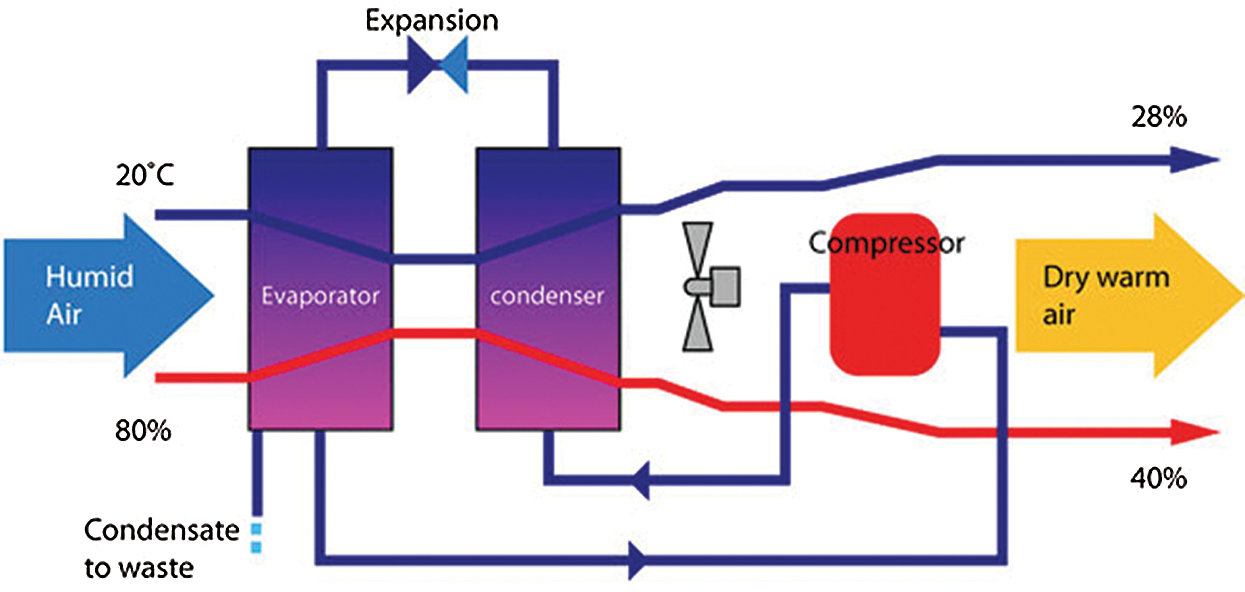
Figure 5: Principle of operation air to air dehumidifier [37]
The evaporative coolers have been used by the ancient Egyptians to cool down the air in buildings 2500 B.C. The new technology of these equipment were started in the USA. Many of those equipment were also designed and used for the first time in Arizona and California [38,39]. Soon these equipment spread around the world in a wide range of marketplaces.
Many air-cooling methods for lowering the dry-bulb temperature DBT exit nowadays and are applied particularly in dry-hot climates. Actually there are two types of evaporative cooling systems ECS which are the direct and indirect evaporative systems.
3.2.1 Direct Evaporative Cooling
The principle behind ECS are converting sensible heat to latent heat. Direct evaporative cooling system DECS, the air is in contact directly with moisture such as a wet medium, liquid, or even spray as shown in Fig. 6 [40,41]. The objective of the DECS is to reduce the temperature of the air by adding water vapor to the air. This transferred energy is used to reduce the air temperature (DBT), however, the humidity increases and this whole process happens at constant enthalpy.
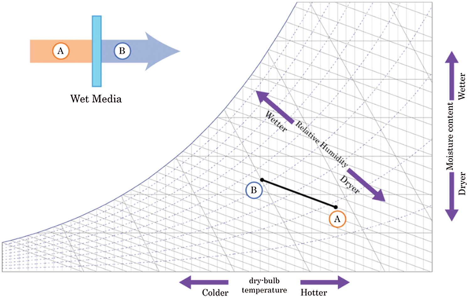
Figure 6: The direct evaporative cooler with schematic diagram and psychometric process
The extensive mathematical and experimental work done by Camargo on the DEC air conditioning system reveals that ECS have a high opportunity and potential to provide thermal comfort conditions in many hot-humid regions [40].
3.2.2 Indirect Evaporative Cooling (IEC)
As shown in Fig. 7, the main component of indirect evaporation is a heat exchanger (tube heat exchanger, plate heat exchanger, or rotary heat exchanger). The heat exchanger works by sensibly cooling the air stream without direct contact with the air stream. Therefore, no moisture is added to the incoming air.
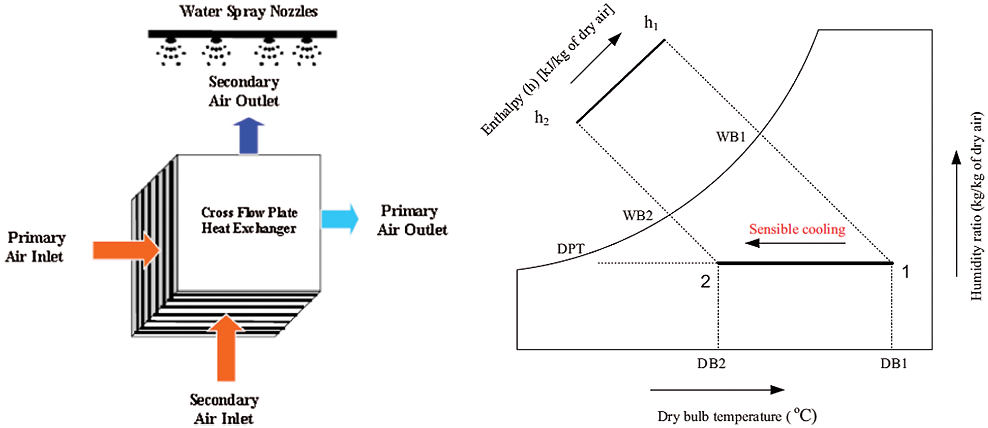
Figure 7: The IEC with schematic diagram and psychometric process [42]
The evaporative cooling principles were presented by Sheng et al. [41] to attain human thermal comfort for indoor conditions. Fig. 8 illustrates the difference between the mechanical cooling system and the DEC in the cooling process on the psychometric chart [43]. As shown in the chart higher value of mass flow rate is needed for EC than the conventional AC to maintain the same cooling load due to lower enthalpy difference. Performance comparison and characteristics of different types of ECS are shown in Tab. 1.
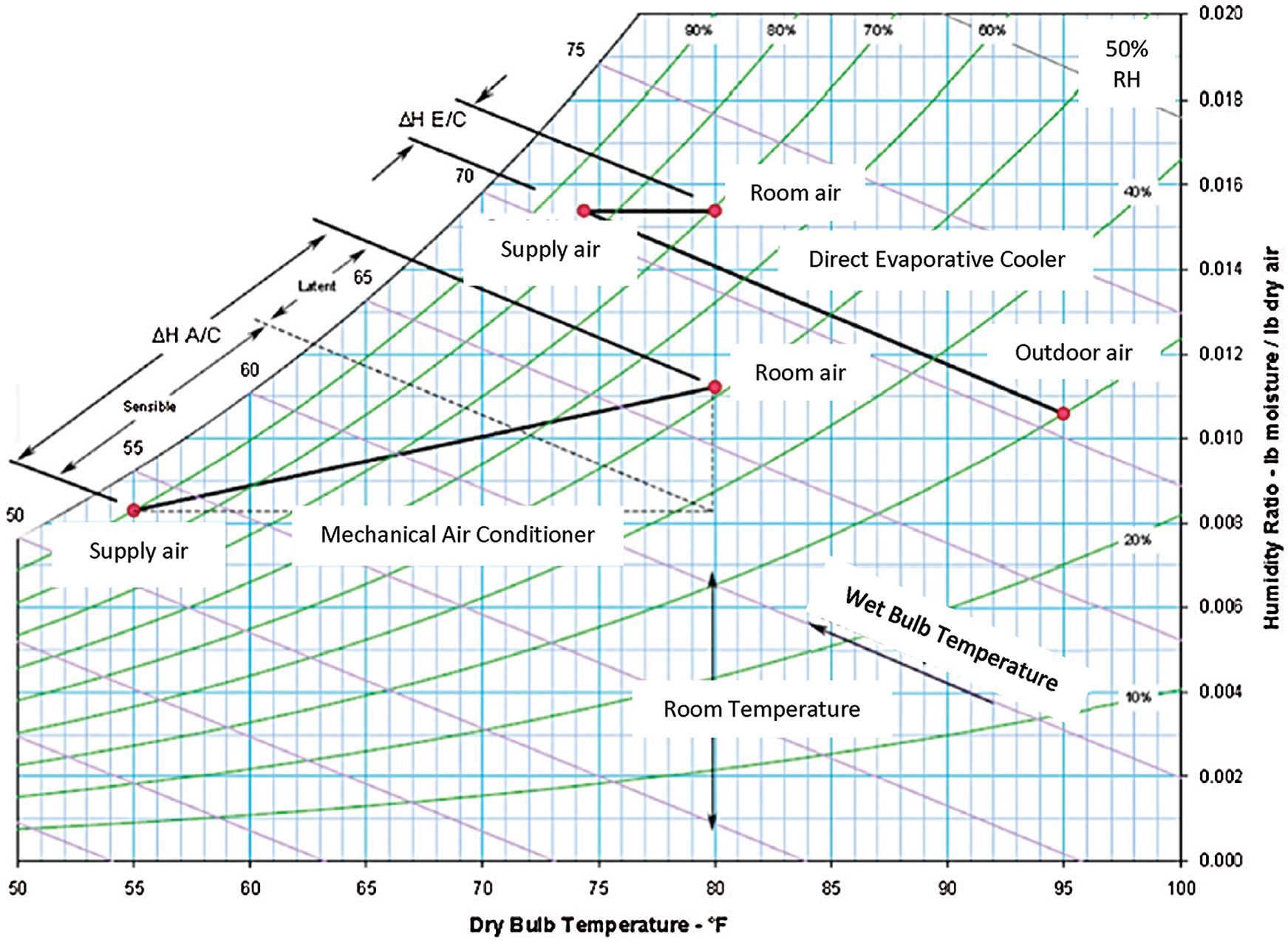
Figure 8: Mechanical cooling system and the DEC the psychometric chart [43]
Table 1: Types and characteristics of ECS [44]

4 Desiccant Cooling Principles and Concepts
The main principle of desiccant cooling is to dehumidify the incoming outside air by directing it through a desiccant material and then removing the moisture to dry the air to the desired room temperature. In order to keep the system functioning continually, the absorbed water vapor should be taken out of the desiccant material so that it will be dried and able to absorb moisture in the next cycle. This is called regeneration process which consist to heat up the desiccant material to a certain temperature. Therefore, a desiccant cooling system (DCS) consists of three main components, the regeneration heat source, the dehumidifier (desiccant material), and the cooling unit as represented in Fig. 9 below.
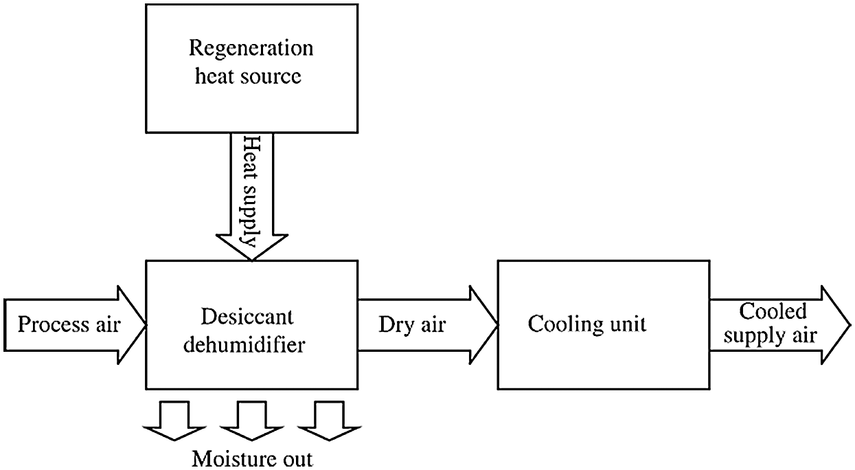
Figure 9: Principles of desiccant cooling
The DCS efficiency is strongly dependent on the Sensible Heat Ratio (SHR). SHR can be defined as “the ratio of the sensible heat gain to the sensible and latent heat gain of the space being conditioned”. When the SHR is low it means that the latent load is the predominant compared to the total sensible and latent load which means that the desiccant system is assumed to be effective. Fig. 10 shows the principle of desiccant cooling with different components that contribute all to the desired function of cooling and dehumidification.
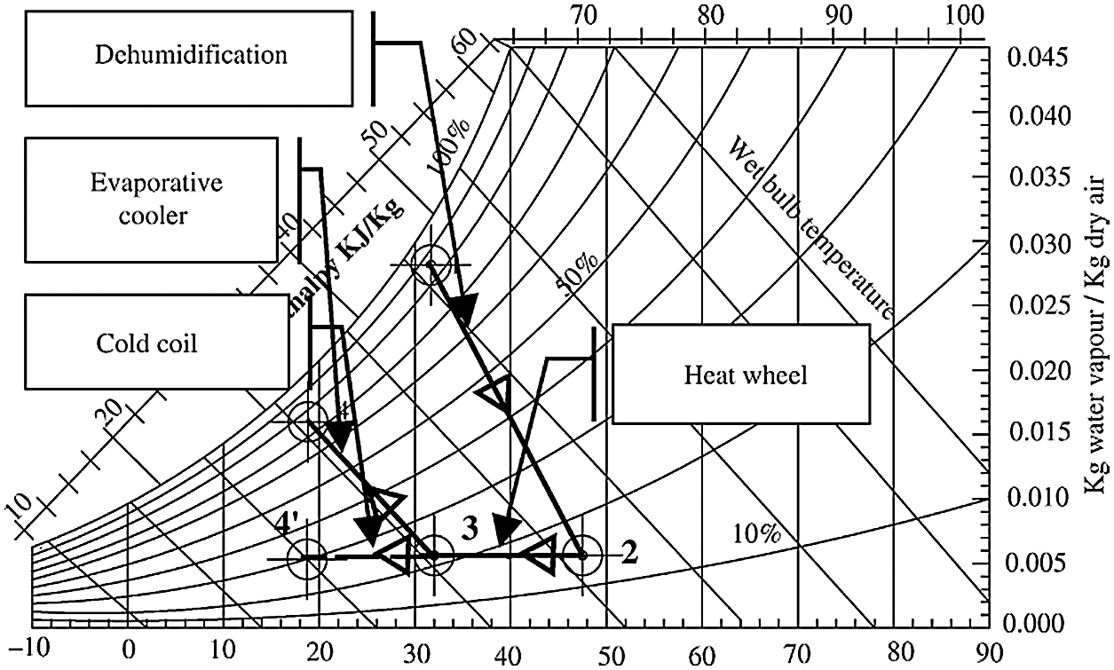
Figure 10: Principle of desiccant cooling on psychrometric chart
A desiccant material that absorb large amounts of moisture and desorb at regeneration temperature is required for the DCS [45]. Desiccants may be classified into two main ways solid or liquid desiccants. New desiccants including composite materials are also developed which gives better results as compared to conventional desiccant silica gel [46–48]. The feasibility of this technique is predicated on low cost and efficient desiccant material, and tons of labor has been published in this repute [47,48].
4.2.1 Overview of Solid Desiccant Cooling
In general, the solid desiccant air-conditioning system utilizes low-grade heat energy and is environmentally friendly [49]. Several arrangements of the solid desiccant cooling system SDCS have been studied and published by several scholars for better thermal comfort performance. Combining the SDCS with heat source and EC has been recently proposed with further improvement on the SDCS by introducing parallel passages in a rotary dehumidifier [50].
4.2.2 Principle of Solid Desiccant Cooling
The SDCS uses a solid desiccant materials made by silica gel in controlling air moisture content by absorbing water vapor from the air [51,52]. Solid desiccants are inexpensive and environmentally friendly. The water vapor in air is removed by the SDCS when it crosses it. The temperature of the air is decreased further by using a sensible heat recovery wheel [53]. Finally, the DCW should be regenerated by heat source to remove the absorbed water vapor (Fig. 11). The desiccant cooling system comprises principally three components: dehumidifier (desiccant material), cooling unit, and regeneration heat source which are illustrated as follows [54].
• Dehumidifier (desiccant material): is generally a slowly rotating desiccant wheel with high capability to absorb the moisture from the air stream [55]. Different types of solid desiccants include colloid, zeolites, activated alumina, titanium silicate, synthetic polymers, lithium chloride, etc. [56]. In the solid desiccant dehumidification, the moisture from the air stream is absorbed by porous and hydrophilic materials [55]. There are some considerations that should be taken into account for the selection of DWs such as, suitable desiccant materials, wheel size, and cost [57]. The performance of the DW depends on several parameters which include inlet and outlet process air temperature and humidity, inlet reactivating air temperature and humidity, face velocity of the two air streams, and size of the regeneration segment [57].
• Cooling unit: which could be an evaporative cooler or a cold coil with capability to remove the sensible heat while the desiccant handle the latent load [58].
• Regeneration heat source: a variety of energy sources can be utilized for this purpose such as solar energy, waste heat, and natural gas heating [59].
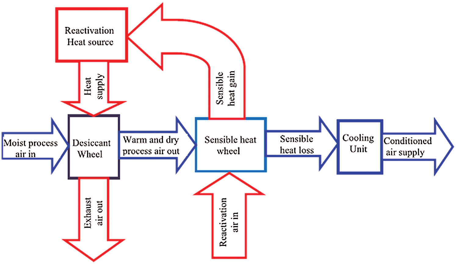
Figure 11: Principles of solid desiccant cooling
4.2.3 Types of Solid Desiccant Cooling Cycles
DCSs can be operated in a ventilation mode, in recirculation mode, and Dunkle cycle [60]. The ventilation cycle was introduced by Pennington as shown in Fig. 12. The humid ambient air dehumidifies by crossing the DSW which results in reduction in moisture content and increase in DBT. The gained sensible heat is removed by the heat recovery wheel HRW (2–3) by passing through it. Then cooled further and dehumidified up to comfort supply conditions (State 4) by passing through the DEC (State 4). Return room air (State 5) is cooled and humidified by passing through another DEC (State 6). This air is then sensibly heated with process air by passing through a sensible HRW (State 7).

Figure 12: Ventilation cycle
The DW is regenerated by heating the warm air through a heat source HS. Around 20% of this air by-pass the HS and exhaust to the ambience (State 9) for energy saving purpose. The heated airstream at state 8 crosses the DW and removes the excessive moisture content [61]. Improvements have been done on Pennington cycle to enhance the cooling capacity by introducing the recirculation cycle as shown in Fig. 13 [62].
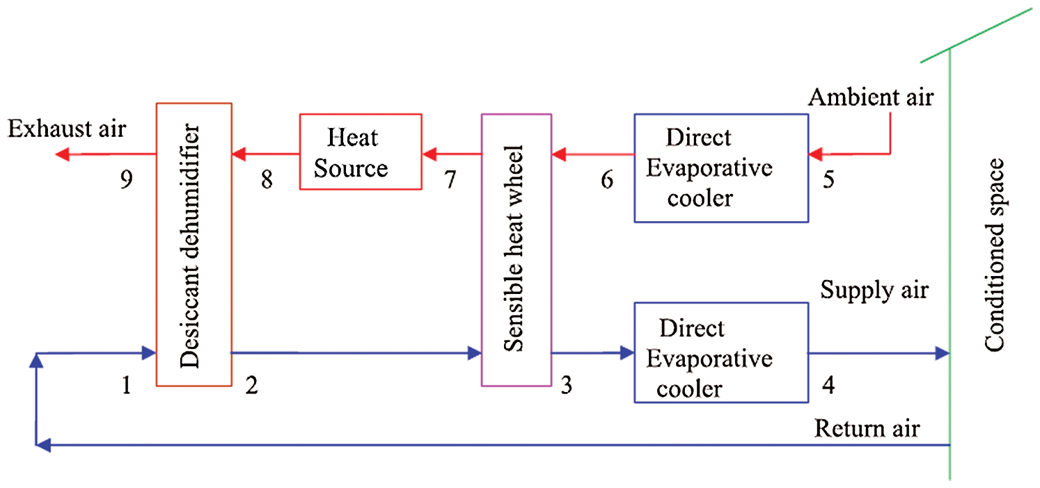
Figure 13: Recirculation cycle
The third type of desiccant cooling cycle is the Dunkle cycle (Fig. 14), thus named after its inventor [63], it combines both the ventilation cycle and the recirculation cycle to enhance cooling capacity. Another SHW is integrated in the system to lower the temperature for the sensible heat exchanger [64].
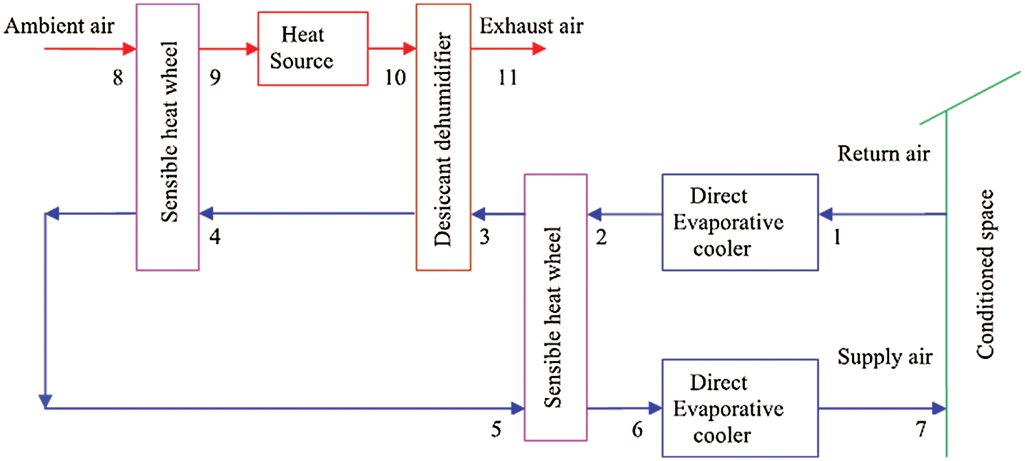
Figure 14: Dunkle cycle
Different SDCS are shown in Fig. 15. The supply room air temperature is lowest in the case of the recirculation cycle because it reuses 100% building air at the dehumidifier inlet [45]. 100% outdoor air is used for the Pennington cycle, while the thermal coefficient of performance and specific cooling capacity would be reduced for the ventilation cycle.
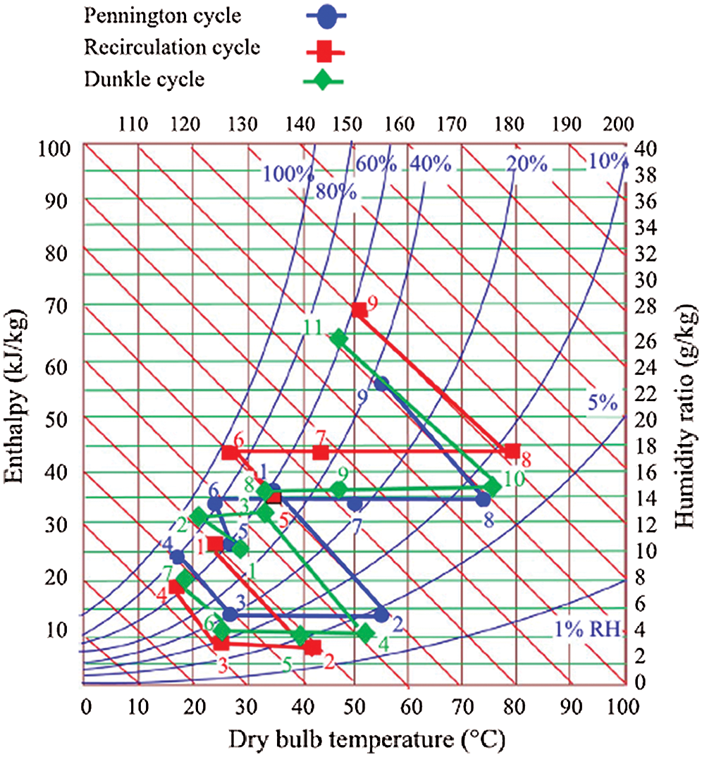
Figure 15: Psychometric chart of solid desiccant cycles
4.2.4 Commented Examples of Solid Desiccant Cooling System
a. a. Solid desiccant aided evaporative cooling
In the system presented in Fig. 16, the outside airstream at state1 crosses the DW. Its moisture is adsorbed and higher its DBT and exits at state 2. From state 2 to state 3 the air is cooled in SHW and then in evaporative cooler from state 3 to state 4. The return air is cooled down by an EC from state 5 to state 6 which will absorb the heat in the HW and increases in temperature when exiting the HW at state 7. The heater will increase the temperature of the air in order to regenerate the desiccant material. To reduce the regeneration heat consumption, about 20% of the return air by-pass the heating source.
b. b. Solid desiccant-aided radiant cooling
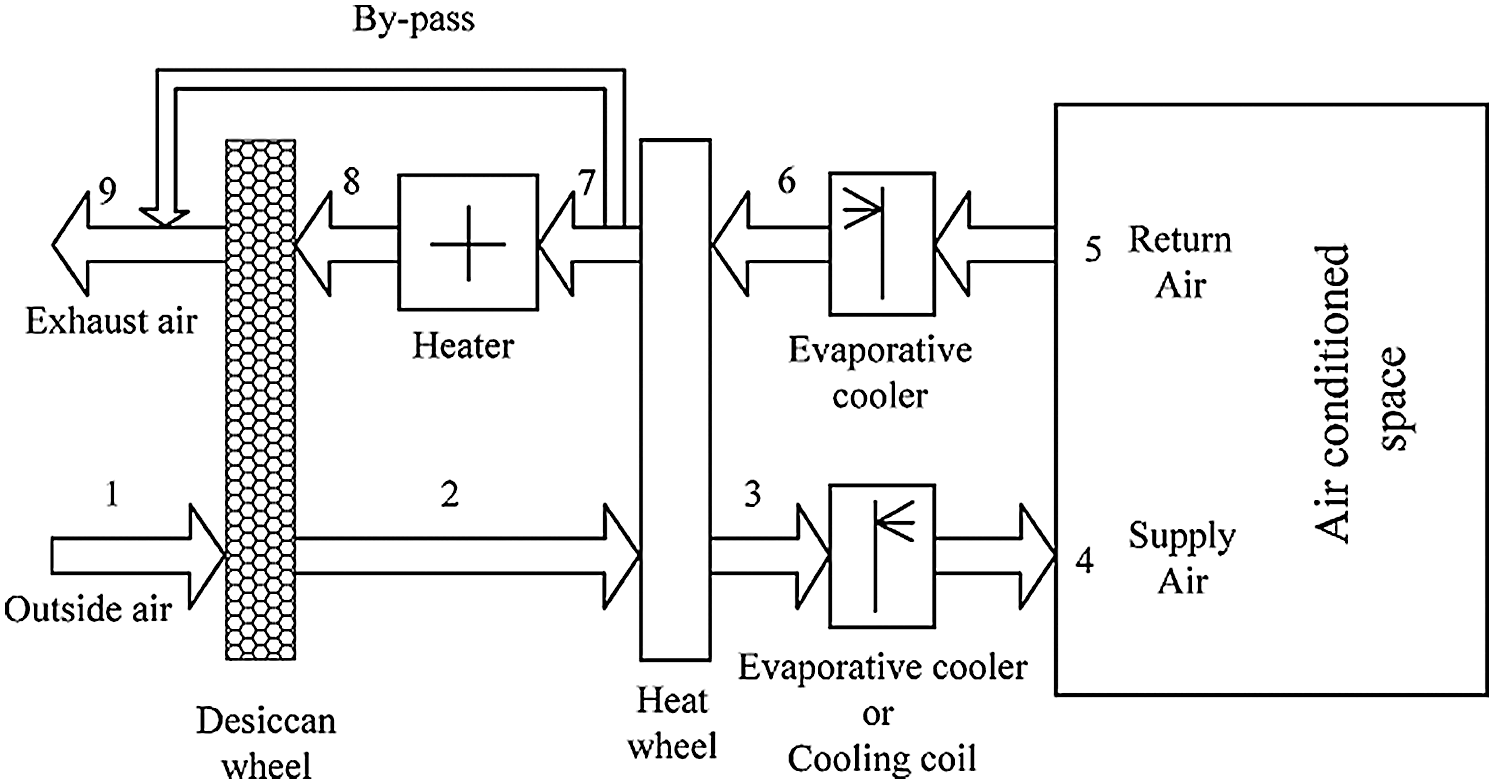
Figure 16: Desiccant dehumidification associate with evaporative
The radiant cooling systems, as shown in Fig. 17, have different types, including metal ceiling panels, chilled beams, and tube embedded ceiling–walls–floors. In this process, the energy transfer is separated from the ventilation which leads to a significant reduction of ventilation air volume with 27% to 37% energy savings [65]. This system presents many advantages as follows:
• Uniform cooling which leads to better comfort to the occupants.
• Less energy consumption since a pump is used.
• No need for ventilation.
In the afternoons on the land mass, as a lower warmed air mass breaks through the higher cooler air mass, creating.
4.3.1 Overview of Liquid Desiccant Cooling
• The increasing need for energy saving and environmental protection led to come up with new energy-saving as well as environmentally friendly air conditioning systems which the liquid desiccant cooling system is principally one of them as it can achieve up to 40% of energy savings [66].
• Many system configurations using liquid desiccant cooling have been studied over the years. The concept is the same, however, the air cooling process and the source regeneration heat differ [67].
• The liquid desiccants are flexibility and they are generally regenerated at relatively lower temperatures [68].
4.3.2 Principle of Liquid Desiccant Cooling (LDCS)
• Liquid systems are very simple in concept. However, they are more complex in hardware, because the liquid desiccant solution can be corrosive, and because the components of the system can be located in different parts of a building with interconnecting piping. In the past, this flexibility of component arrangement has meant that in smaller sizes, liquid desiccant systems were more expensive to install than dry desiccant systems [57]. The principle of the LDCS consists of spraying a desiccant solution and then the air is cooled down in contact with the solution [69].
• The liquid desiccant air conditioning system operates on an open cycle absorption principle and consists of three main components: conditioner, regenerator, and interchange heat exchanger (IHX) [63], which are illustrated as follows and shown in Fig. 18.
• Conditioner: the conditioner is a parallel-plate liquid-to-air heat exchanger. The air temperature leaving the conditioner is less humid with no significant change in its temperature [70].
• Regenerator: the dilute desiccant that leaves the conditioner will go to the regenerator which has the same configuration as the conditioner. The hot fluid flows within the plates and can be supplied by any kind of energy source such as a gas-fired boiler or solar thermal collectors [71].
• Interexchange heat exchanger: the hot, concentrated desiccant that leaves the regenerator and the cool, dilute desiccant that flows to the regenerator exchange thermal energy in the interchange heat exchanger. This exchange increases the efficiency of the regenerator and decreases the cooling load on the conditioner as the heat is transferred from one fluid stream to another across the solid surface of it [55].
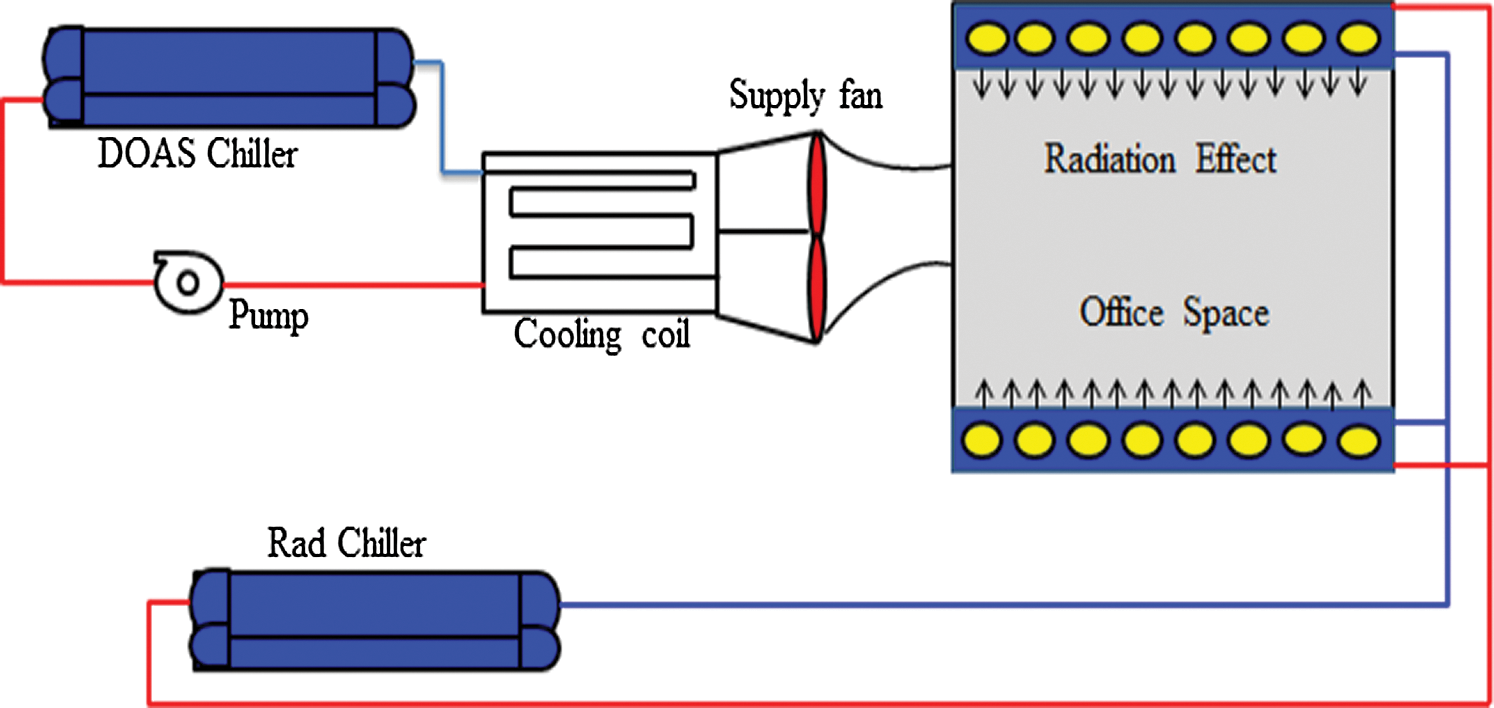
Figure 17: Solid desiccant-aided radiant cooling
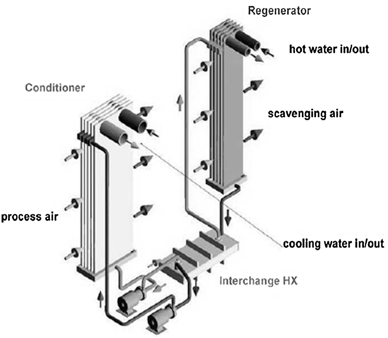
Figure 18: Liquid-desiccant dehumidification system
4.3.3 Commented Examples of Liquid Desiccant Cooling System
a. Vapor compression air conditioning aided liquid desiccant cooling system
The cool strong desiccant solution is sprayed onto the top of the dehumidifier through spraying nozzles as shown in Fig. 19. By gravitation, it trickles through the structure of the dehumidifier where it gets contact with the process air stream blown perpendicularly to its trickling flow direction. Since the cool and strong desiccant solution vapor pressure is less than that of the air vapor pressure, water vapor migrates from the air stream to the desiccant solution and condenses therein. Consequently, the heat of condensation and mixing are liberated causing an increase in the solution’s temperature. The process air stream is slightly cooled down in contact with the cold desiccant solution. The dehumidified and rather warm process air stream then passes through the evaporative cooler before been discharged into space [50,72].
b. Evaporative cooling complemented with liquid desiccant
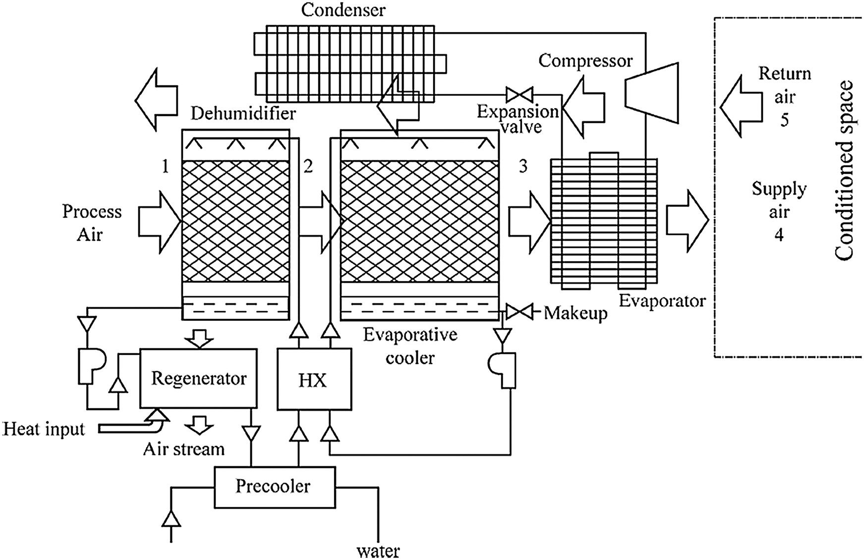
Figure 19: Schematic of liquid desiccant aided vapor compression air conditioning
In this system, the liquid desiccant is used in conjunction with the ECS to form standalone applications as shown in Fig. 20 [73]. On one side of the separating plate, water is brought in contact with the secondary air which is thereby cooled by DEC. This cooled secondary absorbs heat from the primary air on the other side of the plate thus realizing the IEC. This primary airstream is concurrently dehumidified through a crossflow contact with the desiccant solution sprayed using nozzles [50]. This system has a number of advantages. Indeed, solar energy and waste heat can readily be used to drive it and could be used in regions with high cooling needs [40,50].
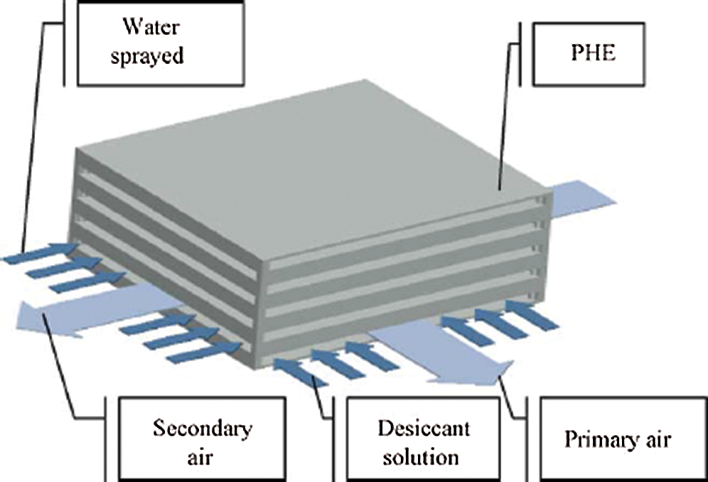
Figure 20: Compact heat exchanger–dehumidifier
4.4 Advantages and Disadvantages of Desiccant Cooling Systems
In general, the desiccant dehumidification systems have many advantages as follows:
• The system is environmentally friendly.
• The sensible and latent cooling loads can be handled independently.
• High electric utility demand charges, which encourage a shift away from conventional, electrically driven air-conditioning (which requires a heavy daytime loading.
• They offer significant potential for energy savings and reduced consumption of fossil fuels. A small amount of electrical energy is required with a variety of thermal energy sources.
• Indoor air quality is improved with lower humidity.
• With desiccant systems, air humidity, and temperature are controlled separately, enabling better control of humidity [55,74].
The two systems of liquid and solid dehumidification have advantages and disadvantages. Tab. 2 summarizes the advantages and disadvantages of solid and liquid desiccant systems [56,75].
Table 2: Advantages and disadvantages of solid and liquid desiccant systems

4.5 Energy Sources for Solid Desiccant Systems (Regeneration Process)
Electricity source is required to operate pumps, fans, and the heating for the regeneration. The heat energy can be provided through solar thermal systems or any waste heat source.
The process of removing the moisture from the desiccant is called regeneration. The heated air pass through the desiccant causing the desiccant to release the moisture.
Solid desiccants require a high temperature for regeneration. This temperature usually is higher than 80°C. That is why this type of system has a high level of energy consumption. For this purpose is usually used gas, electric, low-level waste heat energy, or solar heat energy [76].
a. Electric Energy
An electrical source of energy is the most commonly used for regeneration process of the desiccant system in spite of its cost which will increase the energy consumption of the whole system [46].
b. Gas Energy
Gas can be used as a source of energy for regeneration as shown in Fig. 21.
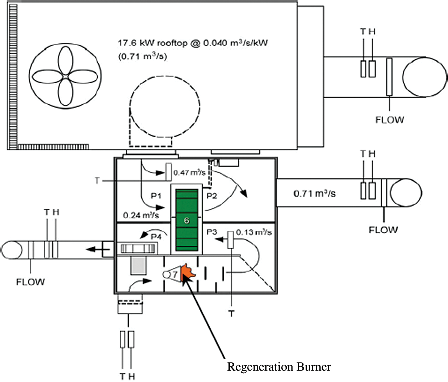
Figure 21: Schematic of desiccant dehumidification/rooftop cooling system
c. Solar Energy
Solar energy is also widely used as a source of energy for the regenerating the desiccants. Three types of regenerating desiccant source from solar energy: solar water, solar air, and solar desiccant are mainly used. The first kind of regenerating desiccant source is a solar water collector. It supplies hot water in order to heat the air regenerator. During the times when there is a lot of solar energy some energy goes to the heat exchange of air regenerator and another part of the solar energy goes to a tank where it is stored for a time when there is not enough energy. The water solar collector is shown in Fig. 22 [1,76].
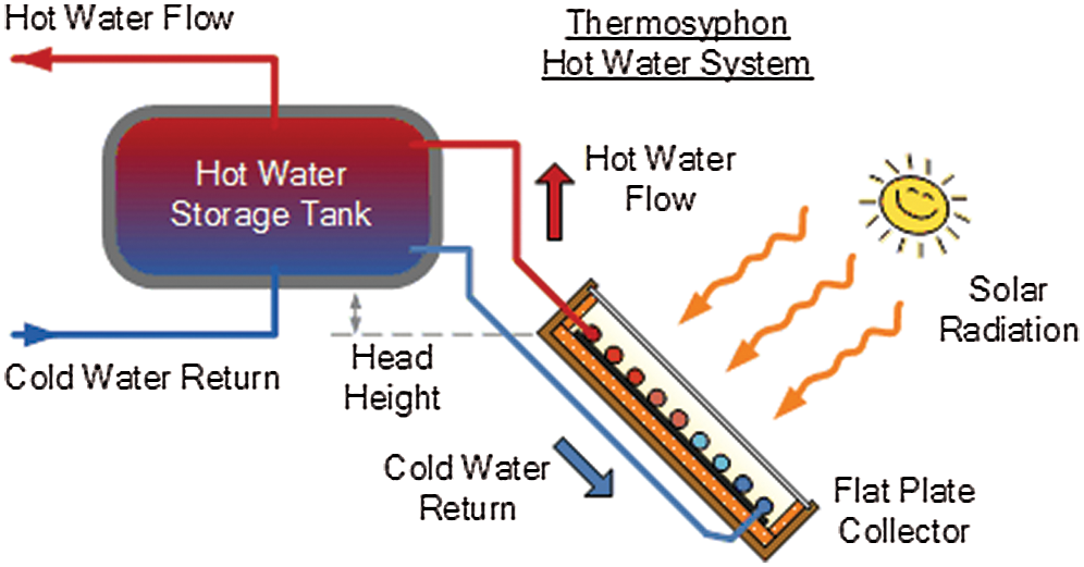
Figure 22: Solar water collector
Another type of solar energy collector is an air solar energy collector (Fig. 23). This system is cheaper than mid-temperature collectors. The temperature, which can be achieved on this installation, is more than 94°C internal temperature of the air and greater than 72°C ambient temperature. In the summer, there is a big range of air temperatures. Because of it, there is a big amount of air for the regeneration of the desiccant. However, to transfer the hot air to the regenerator, it needs a pipe system and good insulation [76].
When comparing solar energy with the other sources of energy we can find out some advantages and disadvantages:
✓ Clean and free energy.
✓ Solar energy is available around the world.
✓ Better storage process compared with solar air.
✓ Better storage capability.
✓ Although the capital costs of utilizing solar energy are high but running costs are less than electric and gas energies.
✓ Electric and gas heaters are more convenient than solar heating systems.
d. Geothermal energy
A DCS can be combined with a geothermal energy source. In this case, borehole heat exchangers are used as a chiller. A heat pump is used for heating the desiccant until its regenerative temperature. It decreases energy consumption by about 30%.
The system with the geothermal source of energy has its advantages and disadvantages. One of the advantages is that the heat sink can have the same level of temperature for better control of the supply air. The disadvantage is the air must be prepared for utilization it by the geothermal heat sink [76].
4.6 Mathematical Modeling of the Solid Desiccant Cooling System
To determine several parameters like temperature, specific humidity, mass flow rate, COP, etc. Mathematical modeling of a solid desiccant cooling system can be used depending on the following equations (see Fig. 24).
According to Daou et al. the effectiveness of the desiccant wheel can be given by [50]:
The effectiveness of the heat recovery wheel is given by:
The effectiveness of DEC:
Applying energy balance on HRW:
Regeneration Heat:
Coefficient of performance (COP) of the system is defined below:
where,
m: mass flow rate of air (kg/min)
w: specific humidity (kg/kg of dry air)
T1 to T9: Intermediate temperatures (°C)
Cp: specific heat of air (kJ/kg°C)
h: specific enthalpy (kJ/kg)
COP: coefficient of performance
ε: effectiveness
5 Solar Assisted Desiccant Cooling System (Case Study: Abu Dhabi City)
The use of AC in several regions of the world lead to a tremendous amount of electricity consumption. Indeed, more than 70% of the electrical power is used by AC systems. Thus, alternative energy could have a great benefit to solve this issue. Renewable energy for instance appears to be promising for such a target.
The main aim of air conditioners is the control of indoor air temperature and humidity. In a typical room we find five categories of loads including the internal and external loads [77]:
• Conduction through the building envelope
• Solar gain through windows
• Ventilation air
• Internal sensible load
• Internal latent load
The United Arab Emirates UAE is characterized with a long hot and humid summers which extend for more than six months. Some desert regions of UAE are hot and dry. Due to such harsh climate the AC system is one of the biggest power consumer in the UAE [78]. Therefore, solar energy is one of the alternative to reduce the energy consumption of these equipment for a desired thermal comfort [79].
The United Arab Emirates is located as one of the major energy users in the world. It exceeds the global development levels in energy use. It is increasing with a mean rate of 10% every year which is more than twice the global growth rate of 4% [79]. The relatively low energy cost in this country compared to the high economic growth and rising population in the past decades has raised energy consumption [80,81].
5.2 Abu Dhabi Location and Climate Type
Abu Dhabi is located in the far west and southwest part of UAE along the southern coast of the Arabian Gulf between latitudes 22°40′ and 25° north and longitudes 51° and 56° east (Fig. 25).
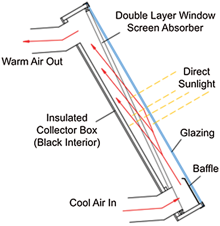
Figure 23: Solar air collector
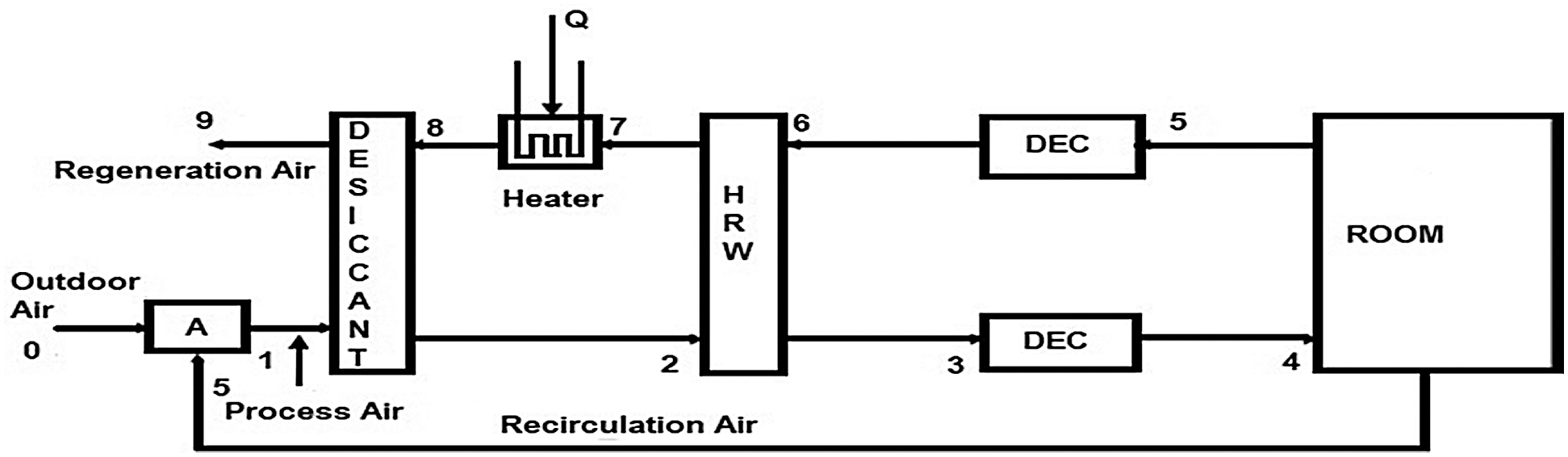
Figure 24: Solid desiccant cooling system with mix (ventilation and re-circulation) mode
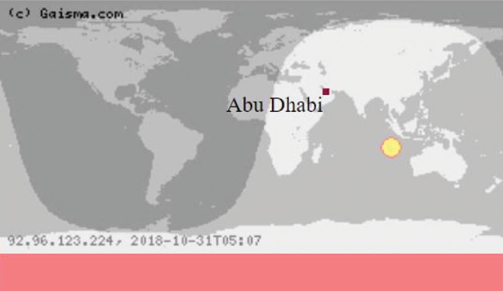
Figure 25: Abu Dhabi city location
The climate is hot and humid during most of the year (Figs. 26 and 27). The temperatures are highest on average in August, at around 34.2°C with a humidity of 70% and the lowest average temperatures occur in January at around 18.2°C. Wind in Abu Dhabi comes from different directions with a few variations in terms of wind velocity. The need for air conditioning in hot seasons, resulting in increased energy demand.
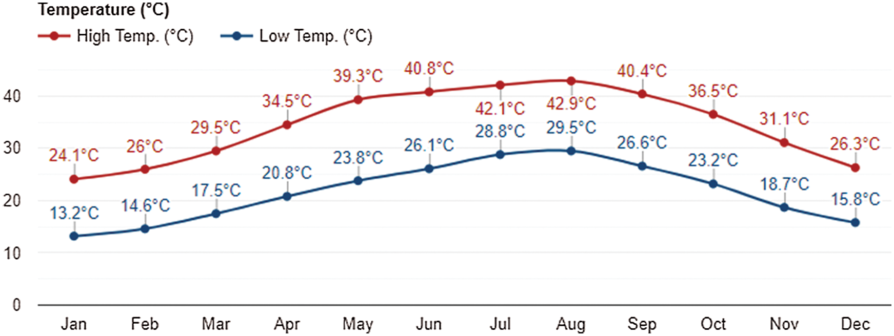
Figure 26: Temperature in Abu Dhabi 2017
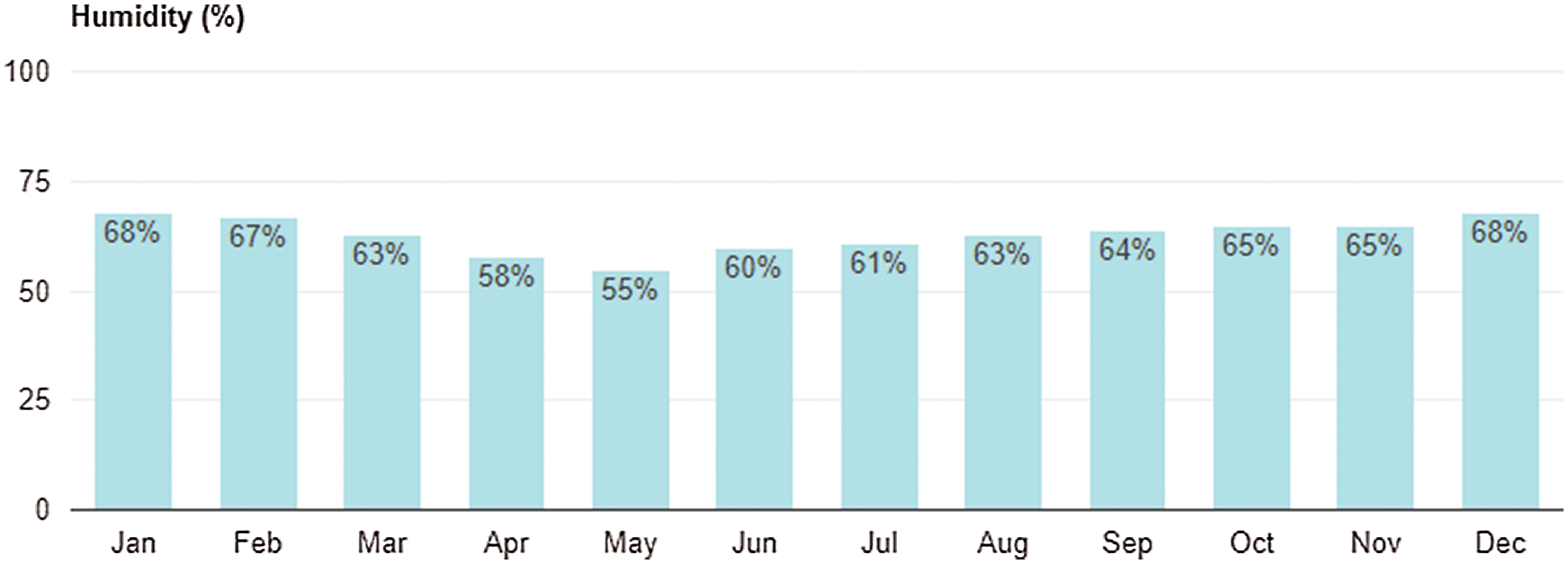
Figure 27: Humidity in Abu Dhabi 2017
5.3 Studies of Using Solar Energy in the Desiccant Cooling System
Previous studies reported that a solar-assisted desiccant cooling system (SADCS) is a very important technology in ACSs. The UAE has a high solar energy potential and it is found that applying solar desiccant air conditioners could be an effective solution to lower cooling demands specifically in the hot-humid period. Some previous investigations reported the potential of the use of the desiccant cooling systems in the UAE as an effective technique for cooling. Although the initial cost of this technology is high, the payback period is expected to be reasonable considering that energy savings are estimated to be in the range of 0% and 50%.
The humidity of spaces is well controlled by the solar desiccant air conditioners. This technique is therefore appropriate for the high level of humidity in summer in most cities in UAE [81]. This concludes that applying the SDCS is possible and feasible in the UAE.
Another research studied the influence of different types of design parameters on the performance of a DCS under two different system configurations [82]. Sphaier and Nobrega did research on the component effectiveness on the ventilation and recirculation DCS performance [83]. Their findings show that, although all components can affect the total system performance but the effectiveness of the HRW and DW have a greater influence. Fong et al. have simulated a SADCS in subtropical Hong Kong [80]. They showed that the SADCS can provide satisfactory performance in subtropical Hong Kong. La et al. suggested a two-stage DCS with IEC instead of DEC [45]. They compared the performance of the proposed system with a one-stage and two-stage DECS. It was concluded that for subtropical outdoor conditions (35, 14 gr/kg), the COP of a two-stage system with an IEC is higher than that of one-stage.
Another work reported a study of solar-powered AC for buildings in hot climates [84]. A computer code has been developed in TRNSYS to simulate a well-insulated single-family residential building, starting from a 3D model of the building architecture, and the SCS.
5.4 Case Study of the Solar-Assisted Solid Desiccant Cooling System in Abu Dhabi City in the UAE
The studied model of a solid desiccant cooling system uses the solar thermal system to pre-heat the desiccant solution for regeneration. In general, the solar thermal system converts sunlight into heat and consists of the following components: collector, storage technology, and regulator system (see Figs. 28 and 29).
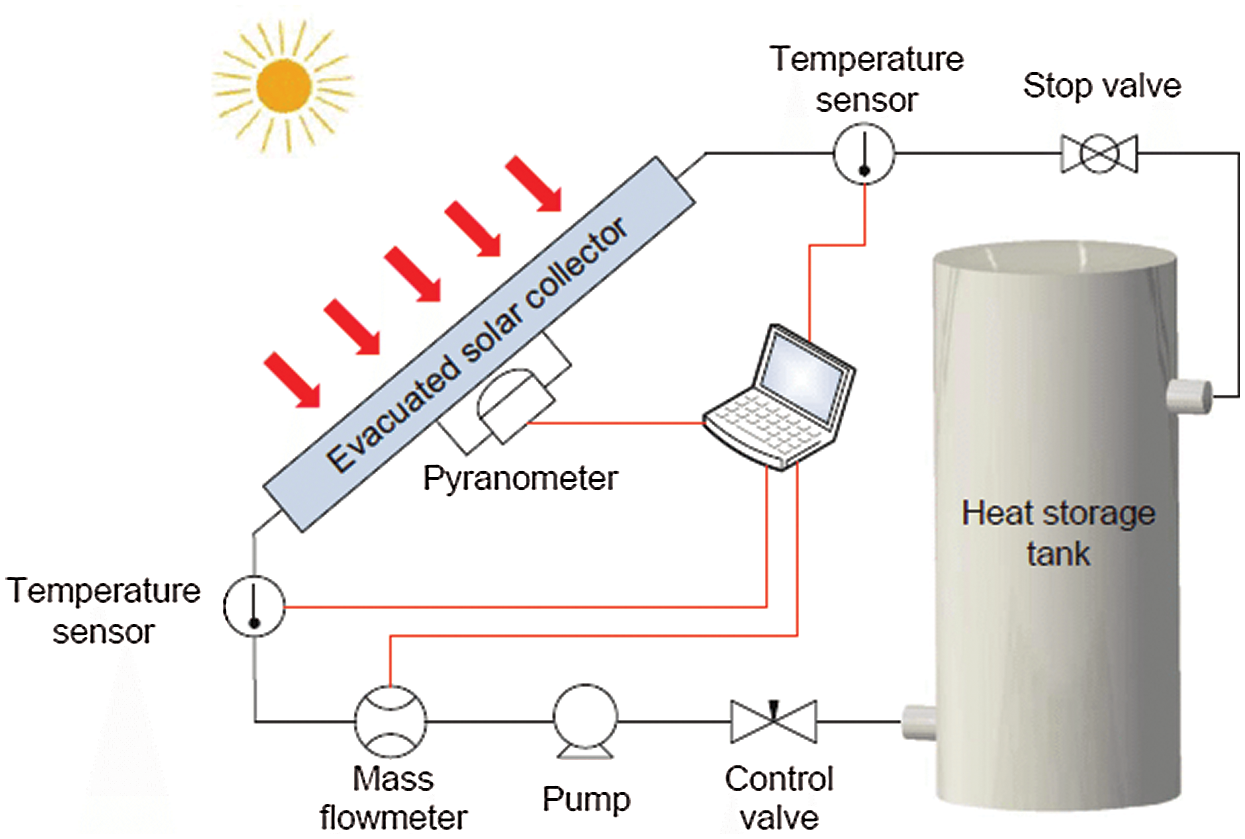
Figure 28: Solar thermal system
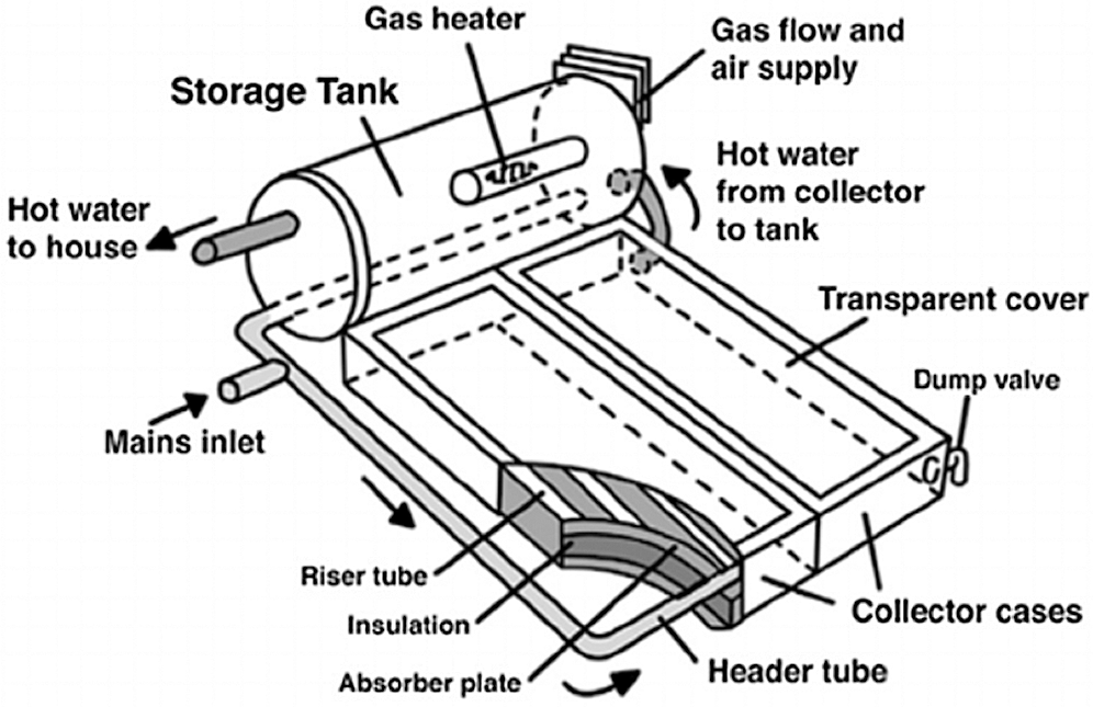
Figure 29: Solar collector
The solar collectors (panels) consists of three types including 1) flat Plate collector, delivering output temperature of around 70°C; 2) evacuated tube collector, delivering output temperature in the range of 100°C–150°C; and 3) concentrating solar collector, delivering output temperature of over 150°C. The first temperature range is that above 8°C, fits for applying with the ACS, while the second are those between 0°C to 8°C as summarized below and shown in Fig. 30.
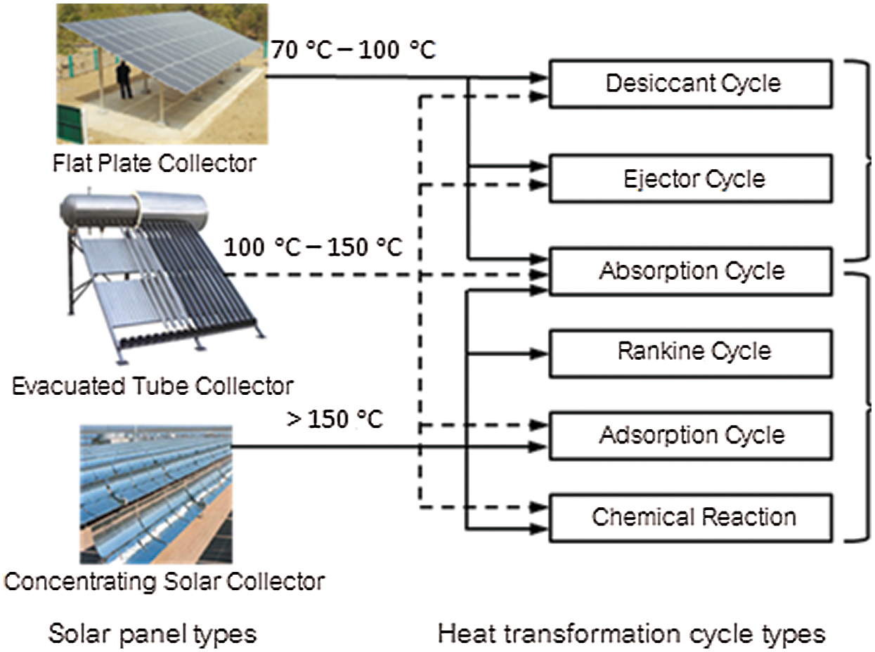
Figure 30: Types of solar collectors
The simulation model is shown in Fig. 31 and all the transformations of the airflow through different stages within the whole system are described in Fig. 32. The air enters the solid desiccant wheel at point 1. After dehumidification, the temperature of process air raises due to adsorption. Process air is sensibly cooled between state points 2 and 3 in the heat recovery wheel. It is further cooled between state points 3 and 4 by an evaporative cooler before entering the room. After leaving the room, return air passes through the heat recovery wheel before the air passes through the heat exchanger at 6–11. Between points 11–12, regeneration air removes moisture from the dehumidifier by desorption process at around 80°C before leaving for the atmosphere. In the TRNSYS simulation studio project as shown in Fig. 33, the model contains rotary dehumidifier (type 683), heat wheel (type 667a), evaporative cooler (type 506), house (type 88), pump (type 3b), is flat plate collector (type 73), heat exchanger (type 91), weather data (type 109-TMY2), psychometrics (type 33e), stratified tank (type 4c) and plotter (type 65c). Abu Dhabi Weather file was used in the simulation.
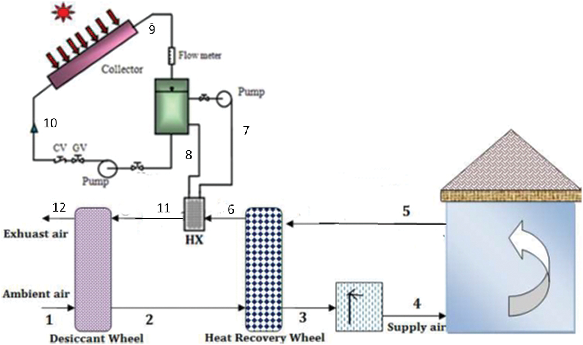
Figure 31: Simulation model
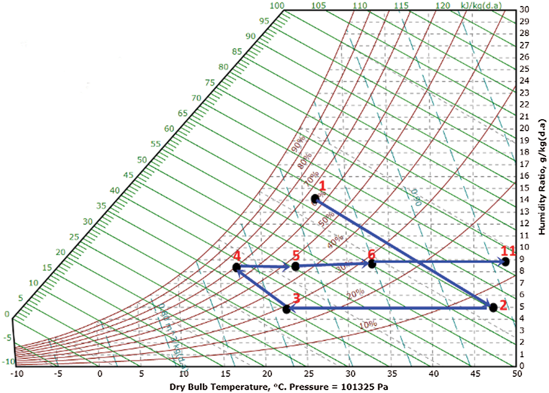
Figure 32: Transformation process of the airflow through each stage of the solar desiccant system

Figure 33: TRNSYS simulation studio of the solar assisted SDCS
5.4.3 Results of the Simulation
The result of the simulation shows through the Figs. 34–44 for 24 h. The inlet and outlet temperatures through the desiccant wheel are shown in Fig. 34. Indeed, we notice the increase of the temperature through the dehumidification process. The desiccant wheel is capable to absorb the moisture when the hot-humid airflow crosses it as shown in Figs. 35 and 36 for the absolute and relative humidities, respectively. When the air crosses the heat wheel its dry bulb temperature decreases as shown in Fig. 37 and the moisture content remains constant. The temperature and moisture conditions in the house are shown in Figs. 38 and 39. Indeed, the relative humidity in the house is within the acceptable level between 30% and below 40% for 24 h. The heat wheel has the capability to heat up the airflow as shown in Fig. 40 which will be further heated cross the heat exchanger as shown in 41. The heat gained from the solar heating system which leads to an increase in the outlet of the water temperature from the storage tank is shown in Fig. 42. Indeed, this heat gain will be transferred to the heat exchanger to increase the temperature of the desiccant wheel regeneration. The heat accumulated in the tank comes from the energy gained by the water outlet from the solar collector. The gradient temperature from the outlet and inlet solar collector is plotted in Fig. 43. The exhaust air temperature from the desiccant wheel is shown in Fig. 44. Indeed, it has been shown by several references that the optimal regeneration temperature for the DW is around 85°C.
a. Desiccant Wheel
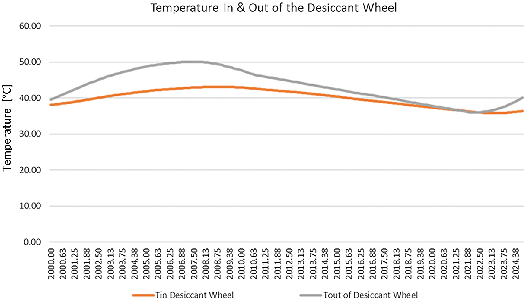
Figure 34: TRNSYS studio project simulation results showing temperature during 24 h (1 day) before and after entering the desiccant wheel (States 1–2)

Figure 35: TRNSYS studio project simulation results showing humidity ratio during 24 h (1 day) before and after entering the desiccant wheel (States 1–2)
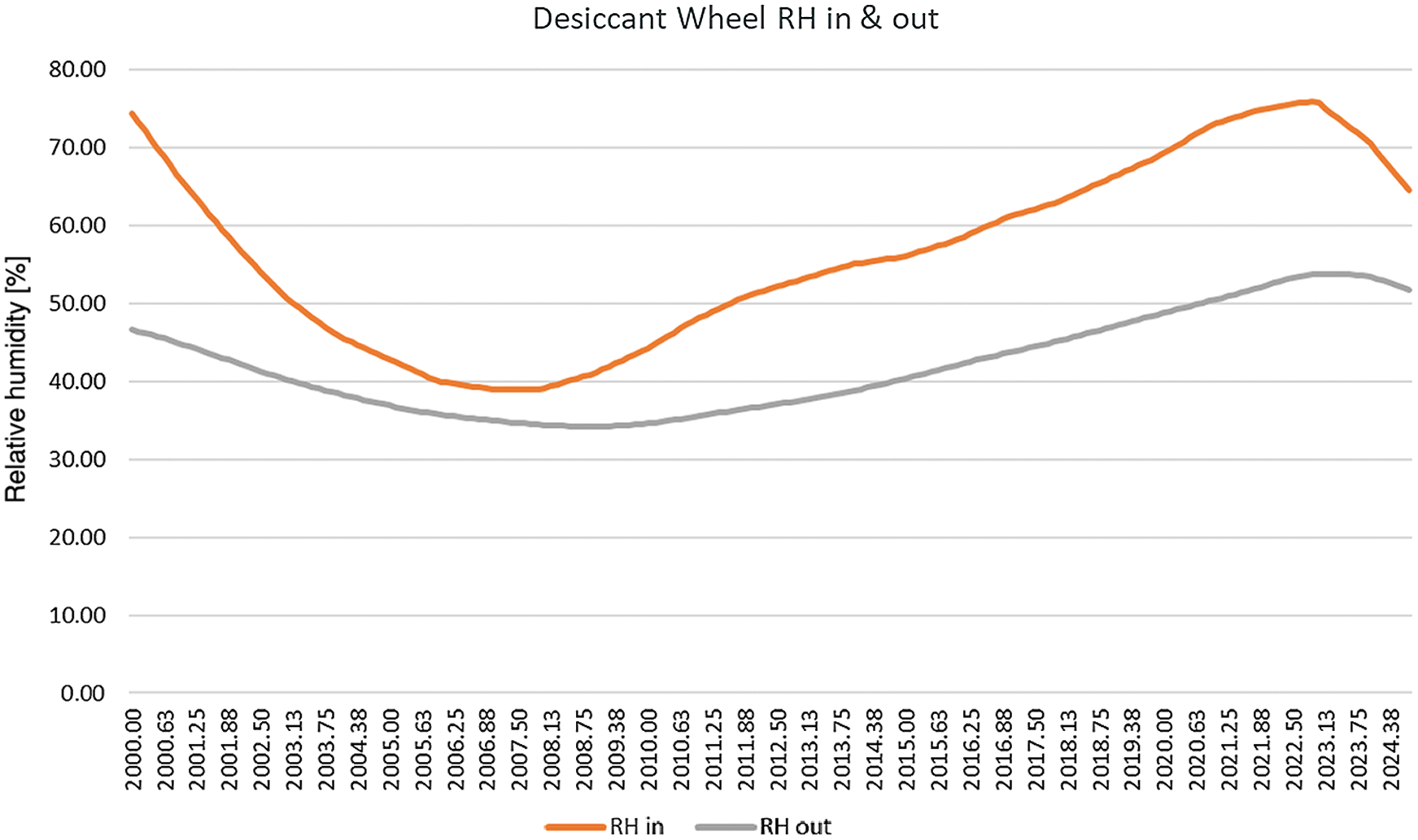
Figure 36: TRNSYS studio project simulation results showing relative humidity during 24 h (1 day) before and after entering the desiccant wheel (States 1–2)
b. Heat Recovery Wheel
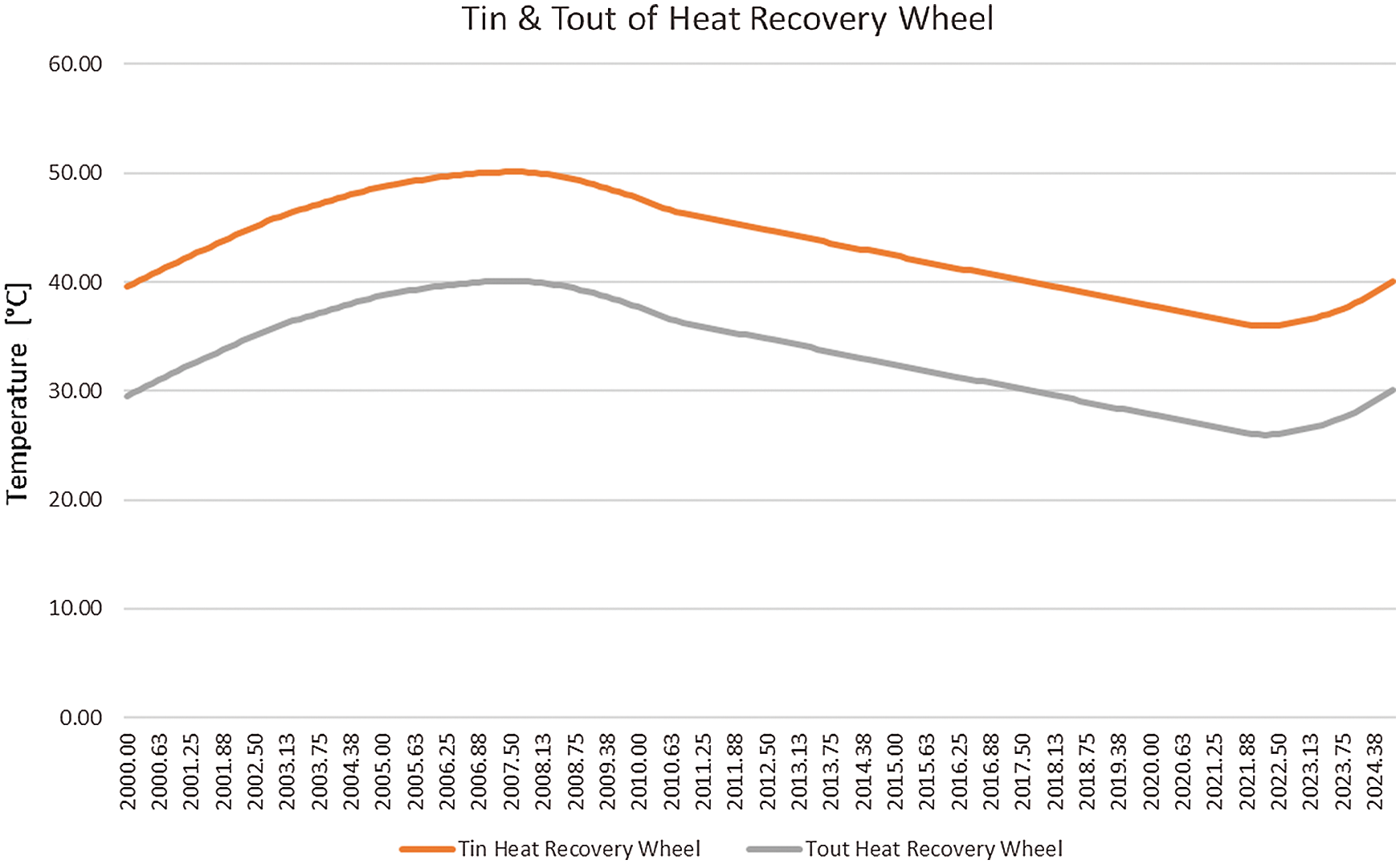
Figure 37: TRNSYS studio project simulation results showing temperature during 24 h (1 day) before and after entering the heat recovery wheel (States 2–3)
c. House Conditions
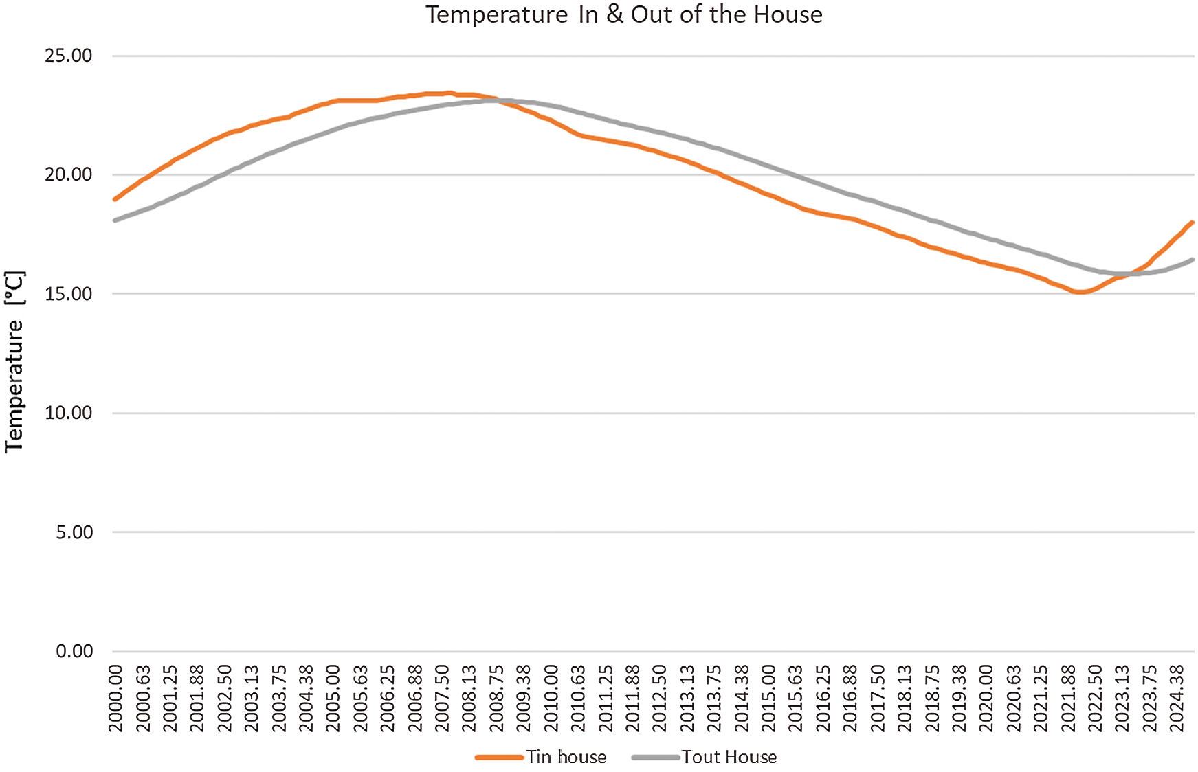
Figure 38: TRNSYS studio project simulation results showing Temperature during 24 h (1 day) before and after entering the house (States 4–5)
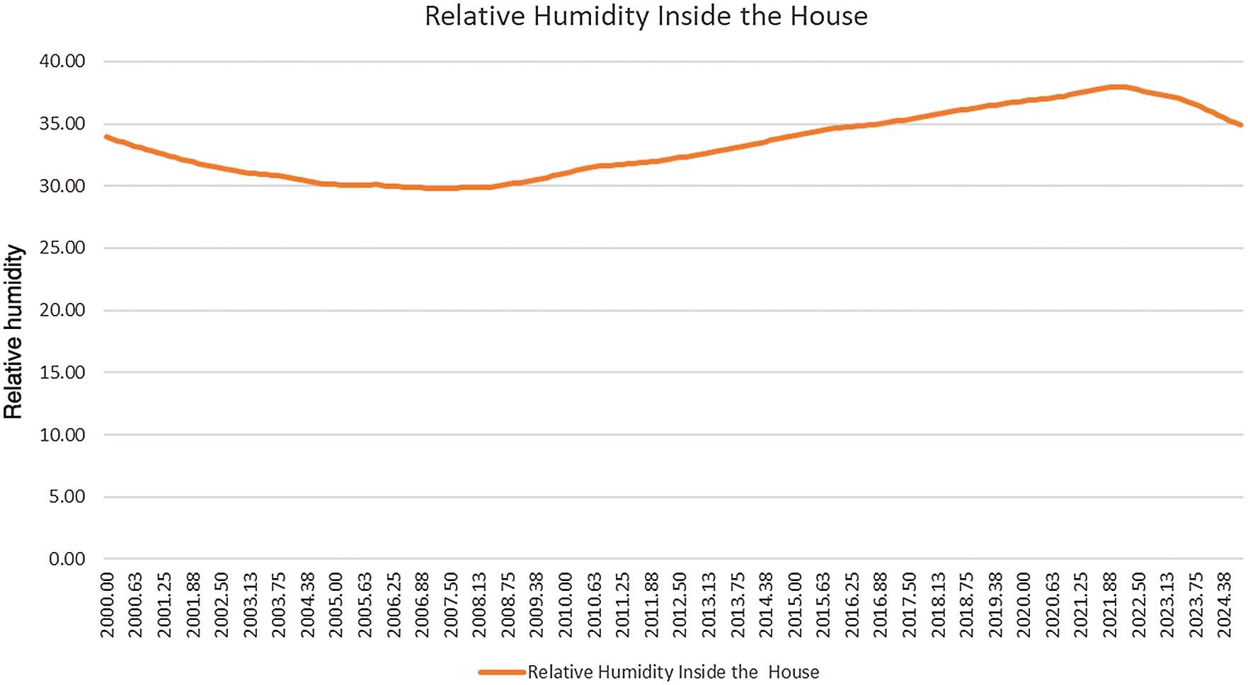
Figure 39: TRNSYS studio project simulation results showing relative humidity during 24 h (1 day) inside the house (States 4–5)
d. Heat Recovery Wheel (Air Return)

Figure 40: TRNSYS studio project simulation results showing temperature during 24 h (1 day) before and after entering the heat recovery wheel (States 5–6)
e. Heat Exchanger
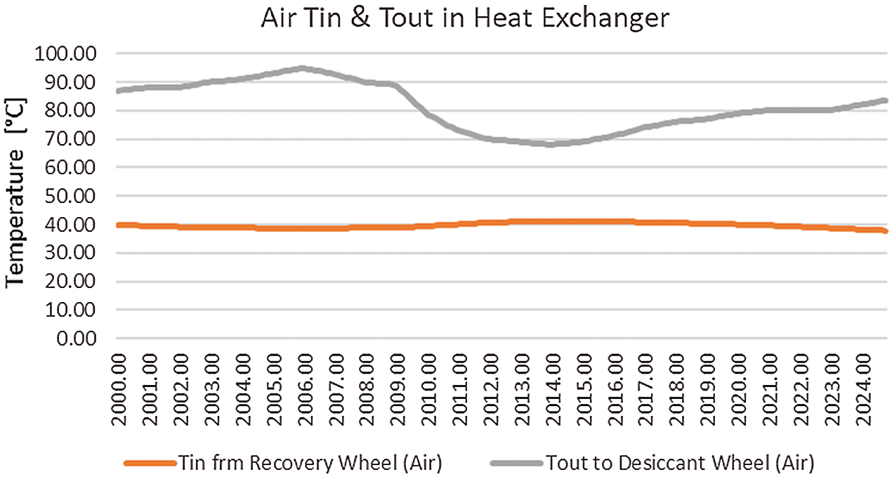
Figure 41: TRNSYS studio project simulation results showing temperature of air during 24 h (1 day) before and after entering the heat exchanger (States 6–11)
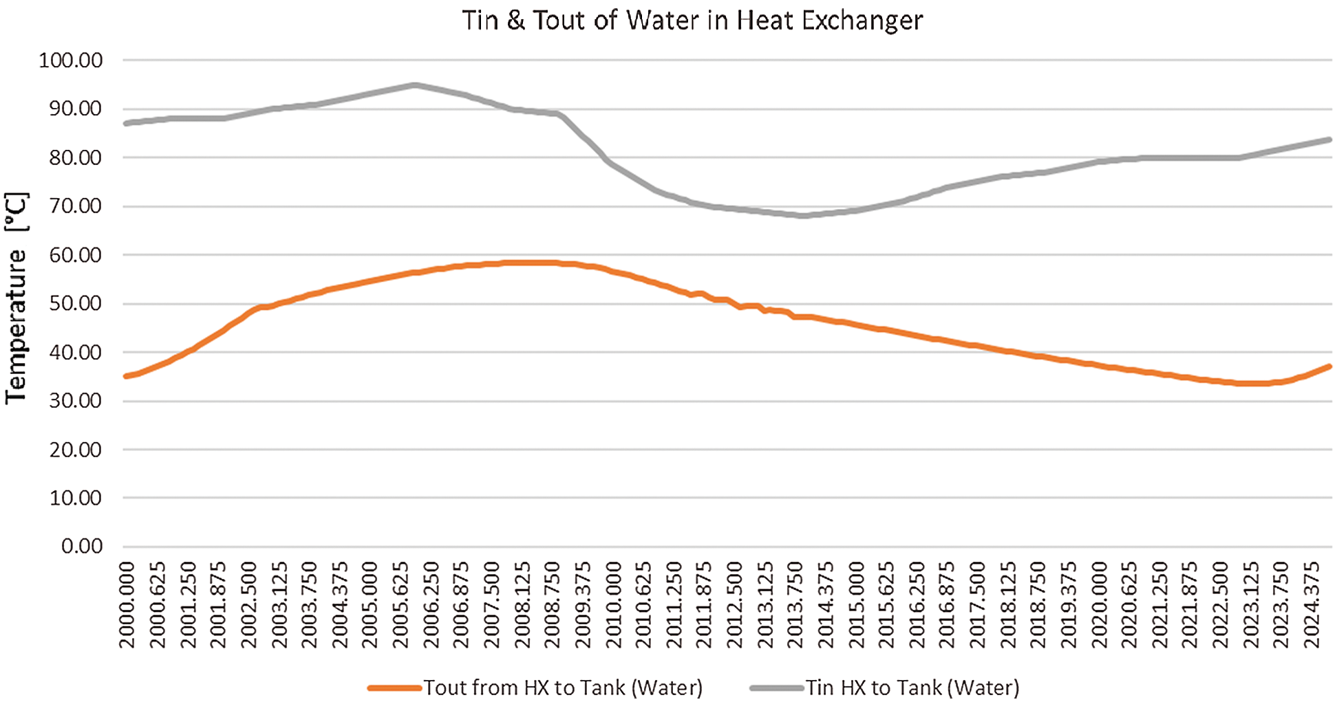
Figure 42: TRNSYS studio project simulation results showing temperature of water during 24 h (1 day) before and after entering the heat exchanger (States 7–8)
f. Solar Collector
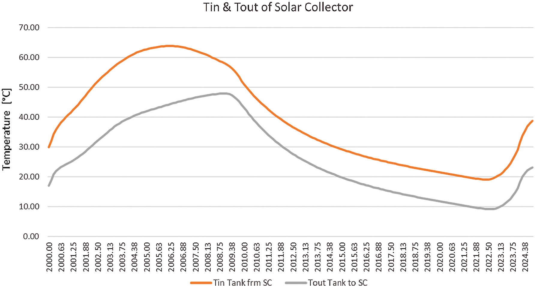
Figure 43: TRNSYS studio project simulation results showing temperature during 24 h (1 day) before and after entering the solar collector (States 9–10)
g. Exhaust Air
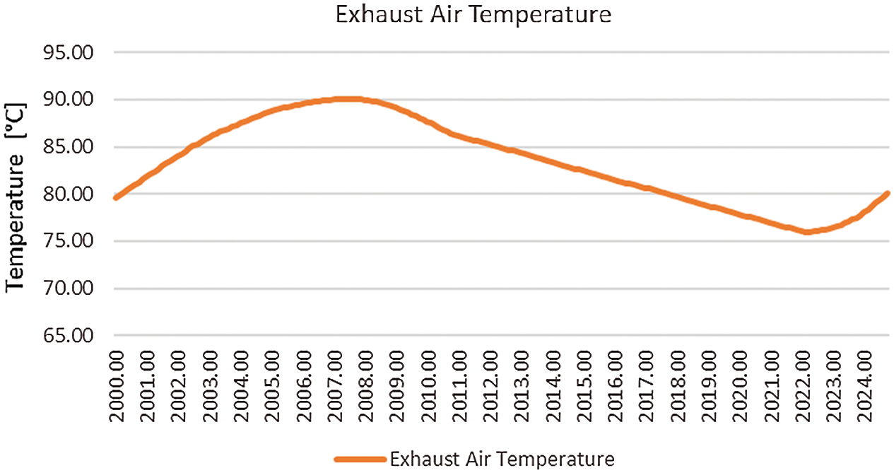
Figure 44: TRNSYS studio project simulation results showing temperature during 24 h (1 day) after exiting the desiccant wheel (State 12)
Desiccant cooling systems are increasingly developed as an alternative to the conventional vapor compression systems since the conventional vapor compression system consumes a large amount of energy and causes environmental problems. So, the desiccant systems become a priority because of the continuing rise in energy demand, increasing cost, and climate change.
The energy required for the cooling and air conditioning is estimated between 30%–40% of total energy use. The cooling energy demand is always increasing because of the occupants’ demands. Accordingly, the usage of a conventional vapor compression system increases the green-house gases in the environment which depletes the ozone layer. The desiccant cooling systems combined with solar energy could be one of the alternatives to solve this issue. One of the main points of applying these systems is that they can use renewable sources of energy such as solar energy or geothermal energy. It means that there is a reduction in CO2 emissions. Also, they do not use any refrigerants which are harmful to the environment. Thereby desiccant systems are better for the environment. There are two types of desiccant cooling systems: solid desiccant systems and liquid desiccant systems. Liquid desiccant systems can be standard and hybrid. Hybrid liquid desiccant systems can be combined with direct, indirect evaporating cooling. Liquid desiccant systems are more effective than solid desiccant systems. They require a smaller regenerative temperature for desiccant. It means that they need less energy. Additional energy such electricity or gas is required for desiccant wheel regeneration. These systems have a sanitizing effect on the air. Airborne microorganisms are killed by passing through the system. Because of the possibility to regulate the level of the relative humidity in the indoor air. There is no dew, so no mold and mildew. Therefore, these systems can prevent building-related illnesses. In addition, desiccant cooling systems can be applied in different climates.
Funding Statement: The authors received no specific funding for this study.
Conflicts of Interest: The authors declare that they have no conflicts of interest to report regarding the present study.
1. Kodama, A. (2005). An energy flow analysis of a solar desiccant cooling equipped with a honeycomb adsorbed. Adsorption, 11, 597–602. DOI 10.1007/s10450-005-5991-7. [Google Scholar] [CrossRef]
2. Ameen, A. (2005). The challenges of air-conditioning in tropical and humid tropical climates. Proceedings of the International Conference on Mechanical Engineering, pp. 28–30Dhaka, Bangladesh. [Google Scholar]
3. NSI/ASHRAE55 (1992). Thermal environmental conditions for human occupancy. American Society of Heating: Refrigerating and Air-conditioning Engineers, Atlanta, GA. [Google Scholar]
4. Zhang, H. B., Hiroshi, Y. (2010). Analysis of indoor humidity environment in Chinese residential buildings. Building Environment, 45(10), 2132–2140. DOI 10.1016/j.buildenv.2010.03.011. [Google Scholar] [CrossRef]
5. Zhang, L. Z., Zhu, D. S., Deng, X. H., Hua, B. (2005). Thermodynamic modeling of a novel air dehumidification system. Energy & Building, 37(3), 279–286. DOI 10.1016/j.enbuild.2004.06.019. [Google Scholar] [CrossRef]
6. Zhang, L. Z., Liang, C. H., Pei, L. X. (2010). Conjugate heat and mass transfer in membrane-formed channels in all entry regions. International Journal of Heat Mass Transfer, 53(5–6), 815–824. DOI 10.1016/j.ijheatmasstransfer.2009.11.043. [Google Scholar] [CrossRef]
7. ASHRAE (2001). Ventilation for acceptable indoor air quality. ANSI/ASHRAE Standard 62-2001. Atlanta: American Society of Heating, Refrigerating, and Air-Conditioning Engineers, Inc. [Google Scholar]
8. Liang, C. H., Zhang, L. Z., Pei, L. X. (2010). Performance analysis of a direct expansion air dehumidification system combined with membrane based total heat recovery. Energy, 35(9), 3891–3901. DOI 10.1016/j.energy.2010.06.002. [Google Scholar] [CrossRef]
9. Mahmud, K., Mahmood, G. I., Simonson, C. J., Besant, R. W. (2010). Performance testing of a counter-cross-flow run-around membrane energy exchanger (RAMEE) system for HVAC applications. Energy & Building, 42(7), 1139–1147. DOI 10.1016/j.enbuild.2010.02.005. [Google Scholar] [CrossRef]
10. Silveira, J. J., Espindola, A. L., Penna, T. J. P. (2006). Agent-based model to rural-urban migration analysis. Physica A, 364, 445–456. DOI 10.1016/j.physa.2005.08.055. [Google Scholar] [CrossRef]
11. York, R. (2007). Demographic trends and energy consumption in european union nations, 1960–2025. Social Science Research, 36(3), 855–872. DOI 10.1016/j.ssresearch.2006.06.007. [Google Scholar] [CrossRef]
12. Barrrios, S., Bertinelli, L., Strobl, E. (2006). Climatic change and rural-urban migration: The case of sub saharan Africa. Journal of Urban Economics, 60(3), 357–371. DOI 10.1016/j.jue.2006.04.005. [Google Scholar] [CrossRef]
13. IEA (2008). Key world energy statistics. Paris, France: International Energy Agency. [Google Scholar]
14. IPCC (2005). Special report on safe guarding the ozone layer and the global climate system. Intergovernmental panel on climate change. http://www.unep.fr/ozonaction/information/mmcfiles/4284-e.pdf. [Google Scholar]
15. Luken, R., Grof, T. (2006). The Montreal protocol’s multilateral fund and sustainable development. Ecological Economics, 56(2), 241–55. DOI 10.1016/j.ecolecon.2004.04.013. [Google Scholar] [CrossRef]
16. Aldy, J. E., Stavins, R. N. (2008). Climate policy architectures for the post-kyoto world. Environment, 50, 6–17. http://hdl.handle.net/10419/26462. [Google Scholar]
17. Coiante, D., Barra, L. (1996). Renewable energy capability to save carbon emissions. Solar Energy, 57, 485–491. DOI 10.1016/S0038-092X(96)00136-3. [Google Scholar] [CrossRef]
18. Green, C., Baksi, S., Dilmaghani, M. (2007). Challenges to a climate stabilizing energy future. Energy Policy, 35, 616–626. DOI 10.1016/j.enpol.2006.01.005. [Google Scholar] [CrossRef]
19. Berne, R. M., Levy, M. N., Koeppen, B., Stanton, B. A. (1998). Physiology. Fourth edition, pp. 519, St. Louis, Missouri: Mosby Publishers. [Google Scholar]
20. American Lung Association, State of the Air (2005). http://lungaction.org/reports/sota05heffects3a.html. [Google Scholar]
21. Freijer, J. I., Bolemen, H. J. (2000). Modeling relationships between indoor and outdoor air quality. Journal of the Air & Waste Management Association, 50, 292–300. DOI 10.1080/10473289.2000.10464007. [Google Scholar] [CrossRef]
22. Brown, F. A., Salas, N. S., Jimenez, M. A. B., Rosales, M. A. (2009). Possible future scenarios for atmospheric concentration of greenhouse gases: A simplified thermodynamics approach. Renewable Energy, 34, 2344–2352. DOI 10.1016/j.renene.2009.03.031. [Google Scholar] [CrossRef]
23. Lin, M., Oki, T., Holloway, T., Streets, D. G., Bengtsson, M., Kanae, S. (2008). Long-term transport of acidifying in east Asia-part I: Model evaluation and sensitivity studies. Atmospheric Environment, 42, 5939–5955. DOI 10.1016/j.atmosenv.2008.04.008. [Google Scholar] [CrossRef]
24. Calm, J. M., Didion, D. A. (1998). Trade-offs in refrigerant selections: Past, present, and future. International Journal of Refrigeration, 21, 308–321. DOI 10.1016/S0140-7007(97)00089-3. [Google Scholar] [CrossRef]
25. Edmonds, J. A. (2004). Climate change and energy technologies. Mitigation and Adaptation for Global Change, 9, 391–416. DOI 10.1023/B:MITI.0000038846.11924.5f. [Google Scholar] [CrossRef]
26. Bull, S. R., Billman, L. L. (2000). Renewable energy: Ready to meet its promise? The Washington Quarterly, 23, 229–244. DOI 10.1162/016366000560674. [Google Scholar] [CrossRef]
27. Baptiste, P. J., Ducroux, R. (2003). Energy policy and climate change. Energy Policy, 31, 155–166. DOI 10.1016/S0301-4215(02)00020-4. [Google Scholar] [CrossRef]
28. Costa, M. F. B., Costa, M. A. F. (2006). Indoor air quality and human health. Journal of Integrated Management Occupational Health Environment, 1, 1–10. [Google Scholar]
29. Day, A. R., Ogumka, P., Jones, P. G., Dunsdon, A. (2009). The use of the planning system to encourage low carbon energy technologies in buildings. Renewable Energy, 34, 2016–2021. DOI 10.1016/j.renene.2009.02.003. [Google Scholar] [CrossRef]
30. Rudd, A., Henderson, H. I. (2007). Monitored indoor moisture and temperature conditions in humid climate U.S. residences. ASHRAE Transactions, 113, 435–449. [Google Scholar]
31. Brandemueh, M. J. (2000). Humidity control options. Interim report for ASHRAE 1121-RP. [Google Scholar]
32. Amrane, K., Hourahan, G. C., Potts, G. (2003). Latent performance of unitary equipment. ASHRAE Journal, 45(1), 28–31. [Google Scholar]
33. Hawaii Guidelines for Energy Efficient Buildings. Dehumidification guideline. (2004). www.archenergy.com/library/general//chapter7_dehumid_030604.pdf. [Google Scholar]
34. Bas, E. (2004). Indoor air quality: A guide for facility managers, Second edition. Fairmont Press Inc. [Google Scholar]
35. Henderson, H. I., Walburger, A. C., Sand, J. R. (2002). The impact of desiccant dehumidification on classroom humidity level. ASHRAE Transaction, 108, 546–555. [Google Scholar]
36. ANSI/ASHRAE Standard 62-2001 (2001). Ventilation for acceptable indoor air quality. ASHRAE Journal, Atlanta, GA. [Google Scholar]
37. Gately, D. P. (1992). Designing for comfortable cooling season humidity in hotels. ASHRAE Transaction, 98, 1293–1302. [Google Scholar]
38. Watt, J. R. (1997). Evaporative air conditioning handbook, 3rd edition. USA: Prentice Hall. [Google Scholar]
39. Pimenta, J. M. D., Castro, W. P. (2003). Analysis of different applications of evaporative cooling systems. Proceedings of 17th International Congress Mechanical EngineeringSao Paulo. [Google Scholar]
40. Camargo, J. R., Ibinuma, C. D., Silveira, J. L. (2005). Experimental performance of a direct evaporative cooler operating during summer in Brazilian city. International Journal of Refrigeration, 28, 1124–1132. DOI 10.1016/j.ijrefrig.2004.12.011. [Google Scholar] [CrossRef]
41. Sheng, C., Agwu Nnanna, A. G. (2012). Empirical correlation of cooling efficiency and transport phenomena of direct evaporative cooler. Applied Thermal Engineering, 40, 48–55. [Google Scholar]
42. Shariaty-Niassar, M., Gilani, N. (2009). An investigation of indirect evaporative coolers, IEC with respect to thermal comfort criteria. Iranian Journal of Chemical Engineering, 6(2), 14–28. [Google Scholar]
43. Davis, R. A. (2004). Evaluation of Advanced Evaporative Cooler Technologies; Pacific Gas and Electric (PG&E) Customer Energy Management Emerging Technologies Program.Report no. 491-04.7. [Google Scholar]
44. Raffique, M. M., Gandhidasan, P., Rehman, S., Al-Hadhrami, L. M. (2015). A review on desiccant based evaporative cooling systems. Renewable and Sustainable Energy Reviews, 45, 145–159. [Google Scholar]
45. La, D., Dai, Y. J., Li, Y., Wang, R. Z., Ge, T. S. (2010). Technical development of rotary desiccant dehumidification and air conditioning: A review. Renewable and Sustainable Energy Review, 14, 130–147. [Google Scholar]
46. Jia, C. X., Dai, Y. J., Wu, J. Y., Wang, R. Z. (2006). Experimental comparison of two honeycombed desiccant wheels fabricated with silica gel and composite desiccant material. Energy Conversion and Management, 47, 2523–2534. [Google Scholar]
47. Shimooka, S., Yamazaki, M., Takewaki, T., Akashige, E., Ikehata, F. et al. (2006). Development of hydrophilic active carbon for high performance adsorption heat pump. Kagaku Kogaku Ronbunshu, 32, 528–534. [Google Scholar]
48. Shimooka, S., Yamazaki, M., Takewaki, T., Akashige, E., Ikehata, F. et al. (2007). Improvement of water adsorption of activated carbon for adsorption heat pump by hydrophilic treatment. Proceedings of International Symposium on EcoTopia Science, pp. 174–177. Nagoya, Japan. [Google Scholar]
49. Patanwar, P., Shukla, S. K. (2012). Parametric studies of a hybrid desiccant cooling system pradeep. International Journal of Energy Engineering, 2(5), 253–258. [Google Scholar]
50. Daou, K., Wang, R. Z., Xia, Z. Z. (2006). Desiccant cooling air conditioning: A review. Renewable and Sustainable Energy Reviews, 10, 55–77. [Google Scholar]
51. Khoukhi, M. (2013). A study of desiccant-based cooling and dehumidifying system in Hot-humid climate. International Journal of Materials, Mechanics and Manufacturing, 1(2), 191–194. [Google Scholar]
52. Chua, K. J., Islam, M. R. (2015). On the experimental study of composite desiccants for energy efficient air dehumidification. IIUM Engineering Journal, 16(2), 1–11. DOI 10.31436/iiumej.v16i2.600. [Google Scholar] [CrossRef]
53. Taweekun, J., Akvanich, V. (2013). The experiment and simulation of solid desiccant dehumidification for Air-conditioning system in a tropical humid climate. Engineering, 5(1), 146–153. DOI 10.4236/eng.2013.51A021. [Google Scholar] [CrossRef]
54. Penney, T. R., McClain-cross, I. (1985). Promising advances in desiccant cooling. Department of Energy’s Solar Buildings Conference Washington, D.C. SERl/TP-252-2683. [Google Scholar]
55. Yashpalbajaj, Swat (2014). Desiccant cooling system–A novel technique for Air conditioning. International Journal of Engineering Research and Applications, 57–60. [Google Scholar]
56. Sahlot, M., Riffat, S. B. (2016). Desiccant cooling systems: A review. International Journal of Low-Carbon Technologies, 11, 489–505. DOI 10.1093/ijlct/ctv032. [Google Scholar] [CrossRef]
57. Kara, O. (2009). Design of air conditioning system with dehumidification (Master Thesis), Cukurova University. [Google Scholar]
58. Bassuoni, M. M. (2014). Experimental performance study of a proposed desiccant based air conditioning system. Journal of Advanced Research, 5(1), 87–95. DOI 10.1016/j.jare.2012.12.002. [Google Scholar] [CrossRef]
59. Ghatol, S. (2017). Rajput, T. hybrid solar desiccant cooling system. International Journal of Engineering Sciences and Research Technology, 6(12), 569–575. [Google Scholar]
60. Parmer, H. (2011). Desiccant cooling system for thermal comfort: A review. International Journal of Engineering Science and Technology, 3(5), 4218–4227. [Google Scholar]
61. Goldsworthy, M., White, S. (2011). Optimization of a desiccant cooling system design with indirect evaporative cooler. International Journal of Refrigeration, 34, 148–158. DOI 10.1016/j.ijrefrig.2010.07.005. [Google Scholar] [CrossRef]
62. Jia, C. X., Dai, Y. J., Wu, J. Y., Wang, R. Z. (2006). Analysis on a hybrid desiccant air-conditioning system. Applied Thermal Engineering, 26, 2393–2400. DOI 10.1016/j.applthermaleng.2006.02.016. [Google Scholar] [CrossRef]
63. Collier, R. K., Barlow, R. S., Arnold, F. H. (1982). An overview of open-cycle desiccant-cooling systems and materials. Journal of Solar Energy Engineering, 104, 28–34. DOI 10.1115/1.3266271. [Google Scholar] [CrossRef]
64. Muzaffar, A. (2013). Optimization of heating, ventilation, and air-conditioning (HVAC) system configurations. Pakistan: University of Engineering & Technology Taxila. [Google Scholar]
65. Khan, Y., Singh, G., Mathur, J., Bhandari, M., Srivastava, P. (2017). Performance assessment of radiant cooling system integrated with desiccant assisted DOAS with solar regeneration. Applied Thermal Engineering, 124, 1075–1082. DOI 10.1016/j.applthermaleng.2017.06.052. [Google Scholar] [CrossRef]
66. Bouzenada, S. (2018). Experimental performance of a solar thermal liquid desiccant air conditioning system–A review. International Conference on Renewable Energies and Power Quality (ICREPQ’18Salamanca, Spain. [Google Scholar]
67. Oberg, V., Goswami, D. Y. (1983). A review of liquid desiccant cooling. https://www.researchgate.net/publication/283407930_A_review_of_liquid_desiccant_cooling/citations. [Google Scholar]
68. Hamed, A. M., Zeidan, E. B., Alosaimy, A. S., Kassem, T. K. (2012). Application of solar energy for regeneration of liquid desiccant using rotating tilted wick. International Journal Mechanical Mechatronics Engineering, 12(5), 21–29. [Google Scholar]
69. Elsarrag, E. (2018). An innovative smart liquid desiccant Air conditioning system for indoor and outdoor cooling using seawater bittern. Innovative Energy and Research, 7(1), 1–6. DOI 10.4172/2576-1463. [Google Scholar] [CrossRef]
70. Venkatesh, S., Rohit, B. V., Bhargav, N., Rajesh, A., Rambabu, M. (2016). Fabrication of falling film liquid desiccant Air-conditioning system. Fluid Mechanics Open Access, 3(1), 1–8. DOI 10.4172/2476-2296. [Google Scholar] [CrossRef]
71. Lowenstein, A. (2005). High efficiency liquid-desiccant regenerator for Air conditioning and industrial drying. Department of Energy. https://www.osti.gov/servlets/purl/878712. [Google Scholar]
72. Christodoulaki, R. I., Rogdakis, E. D., Koronaki, I. P. (2008). Hybrid liquid desiccant/vapor compression air-conditioning systems: A critical review.Engineering Systems Design and Analysis,vol. 48357, pp. 45–57. [Google Scholar]
73. Saman, W. Y., Alisadeh, S. (2002). An experimental study of a cross-flow type plate heat exchanger for dehumidification/cooling. Solar Energy, 1, 59–71. [Google Scholar]
74. Srivastav, A. (2016). Performance studies for desiccant cooling system. International Research Journal of Engineering and Technology, 3(4), 405–408. [Google Scholar]
75. Powelson, Bart. Decoding Dehumidifying (2016). http://www.ac heatingconnect.com/homeowners/decoding-dehumidifying/. [Google Scholar]
76. Demidova, E. (2013). Desiccant cooling systems. Mikkelli University of Applied Sciences. [Google Scholar]
77. The district cooling market heats up (2008). Danish Board of District Heating-dBDH-Sustainable Energy. [Google Scholar]
78. Strunk, W. J., White, E. B. (2000). The elements of style, Fourth edition. Longman, New York. Solar Cooling and Air-Conditioning. Fraunhofer-Institute for solar energy systems, Department of Thermal Systems and Buildings, Tunis. [Google Scholar]
79. Al-Faris, A. F. (2002). The demand for electricity in the GCC countries. Energy Policy, 30, 117–124. [Google Scholar]
80. Fong, K. F., Chow, T. T. (2007). Application potential of solar-assisted desiccant cooling system in sub-tropical Hong Kong. Proceedings of Clima 2007 WellBeing Indoors. [Google Scholar]
81. Henning, H. M. (2000). Air conditioning with solar energy, vol. 10, no. 3.Barcelona:Fraunhofer-Institute for Solar Energie Systeme. [Google Scholar]
82. Chung, J. D., Lee, D. Y. (2011). Contributions of system components and operating conditions to the performance of desiccant cooling systems. International Journal of Refrigeration, 34(4), 922–927. DOI 10.1016/j.ijrefrig.2011.03.003. [Google Scholar] [CrossRef]
83. Sphaier, L., Nóbrega, C. E. L. (2012). Parametric analysis of components effectiveness on desiccant cooling cycle performance. Energy, 38(1), 157–166. DOI 10.1016/j.energy.2011.12.019. [Google Scholar] [CrossRef]
84. Brumana, G., Franchini, G. (2016). Solar-powered Air conditioning for buildings in Hot climates: Desiccant evaporative cooling vs. absorption chiller-based systems. Energy Procedia, 101, 288–296. DOI: 10.1016/j.egypro.2016.11.037. [Google Scholar] [CrossRef]
 | This work is licensed under a Creative Commons Attribution 4.0 International License, which permits unrestricted use, distribution, and reproduction in any medium, provided the original work is properly cited. |