| Energy Engineering |
DOI: 10.32604/EE.2021.014741
ARTICLE
Effect of Non-Convective Zone Thickness on Thermal Efficiency of Salt Gradient Solar Ponds
1School of Vehicles and Energy, Yanshan University, Qinhuangdao, 066004, China
2Architecture Department, Shijiazhuang Institute of Railway Technology, Shijiazhuang, 050541, China
*Corresponding Author: Caihong Zhang. Email: zchlrt@ysu.edu.cn
Received: 26 October 2020; Accepted: 01 December 2020
Abstract: An improved radiation transmission and thermal efficiency model for solar ponds has been proposed based on both the Hull Model and Wang/Seyed-Yagoobi Model in this paper. The new model is more accurate to actual measured conditions because multiple reflections and turbidity effects are included. Absorption penetration, thermal conductivity loss and thermal efficiency under different Non-Convective Zone thicknesses are numerically analyzed and thoroughly discussed. The results show that ΔT/I0 plays a critical role for the thermal efficiency of solar pond. Furthermore, it is found through calculation that there is an optimum thickness of the Non-Convective Zone. When the Non-Convective Zone thickness is less than this critical threshold, both temperature and thermal efficiency are decreased with increasing turbidity. However, when the Non-Convective Zone thickness is greater than this critical threshold, the increasing turbidity within a certain range will be beneficial to improve the thermal efficiency of solar pond. In addition, optimum Non-Convective Zone thickness is also related to the temperature, turbidity, salinity variation and bottom reflectivity.
Keywords: Solar pond; Non-Convective Zone thickness; thermal efficiency; bottom reflective
A salt gradient solar pond is an artificial brine pool with an increasing salinity with depth. This is different from a common brine pool, which is generally homogenous. The salinity gradient is created by a salinity difference created through convection flow. Convention flow is preventing mixing and thermal energy from solar is then collected and stored at the bottom for an extended period of time [1–3]. Generally, a typical solar pond salt gradient is divided into three distinct zones based on the distribution of salinity: Upper Convective Zone (UCZ) is the topmost layer; Lower Convective Zone (LCZ) is the bottommost layer; and Non-Convective Zone (NCZ) lies in-between the UCZ and LCZ [4,5]. The general structure of a solar pond and the temperature and salinity profiles are shown in Fig. 1.
The NCZ thickness is a key factor affecting the thermal performance for a working solar pond [6,7]. When the thickness of the NCZ is less than a critical threshold, a thicker the NCZ up to this threshold can retain more heat in the LCZ, providing a higher thermal efficiency. When the thickness of the NCZ is greater than this critical threshold, the amount of solar energy that can be reached and absorbed to the LCZ is reduced by the NCZ, and both temperature and thermal efficiency are decreased in the pond. Therefore, there is an optimum thickness of the NCZ, which is also affected by turbidity and bottom reflectivity, and has an important influence and significance on improving the thermal performance of a solar pond. Husain et al. [8] used the thermal efficiency model to obtain the optimal NCZ thickness of the solar pond. Prasad et al. [9] carried out theoretical calculations of the NCZ thickness under ideal conditions. Ge et al. [10] constructed a numerical model to simulate the thermal efficiency of solar pools under different NCZ thicknesses. However, the models did not consider the influence of bottom reflectivity and turbidity on the thermal performance of solar ponds. Hawlader et al. [11] considered the bottom reflection of the pond as a specular reflection, and obtained the relationship between the bottom reflection rate and the thermal performance of the solar pond. However, this consideration was not comprehensive, because the bottom of the solar pond should follow the law of diffuse reflection. Kooi [12] considered the diffuse reflection in the calculation of the thermal efficiency of the solar pond, but he did not take into account the multiple reflections between the bottom and the surface of the pond, so it was also incomplete. Hull et al. [13,14] obtained a more comprehensive law of diffuse reflection at the bottom of the pond, and gave a relationship between the bottom reflectivity and the thermal performance of the solar pond, but he did not take the turbidity of the solution into consideration. Wang et al. [15] experimentally investigated the effect of turbidity on penetration of solar radiation at a solar pond for the first time. Their results indicated that turbidity plays a critical role on the magnitude of the penetration of solar radiation. The radiation transmission model (W.S. model) they concluded was later recognized and cited by most scholars.
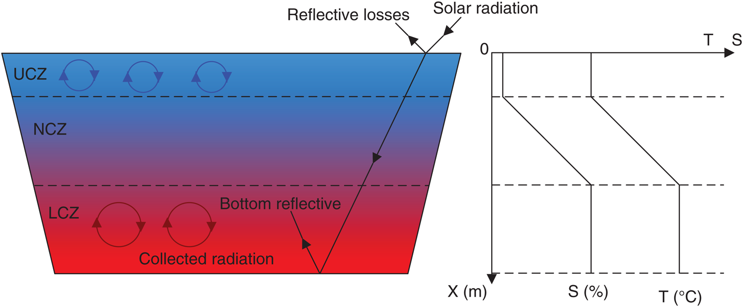
Figure 1: Schematic drawing of a salt gradient solar pond X(m) = depth. S(%) = salinity. T(°C) = temperature
Here, to improve the radiation transmission model, the Hull Model and Wang and Seyed-Yagoobi (W.S.) Model are combined in this paper. This model includes NCZ thickness, turbidity, multiple reflections and attenuation of solar radiation in the brine. A thermal efficiency model is also provided to analyze the influence of the NCZ thickness through simulations.
2 The Improved Radiation Transmission Models
The W.S. model is a widely used and accepted solar pond model that has taken into account the turbidity of a pond and its effect on radiation transmission and thermal performance. Turbidity describes water transparency using Nephelometric Turbidity Units (NTU) to express the extent of turbidity. Wang et al. [15] have also performed many experiments to prove that the reduction of radiation transmission and thermal efficiency in a solar pond is mainly caused by turbidity and not salinity. Their results have indicated that turbidity plays an important role in the thermal performance of a solar pond. When the bottom reflectivity is neglected, the W.S. model can be expressed as Eq. (1) for uniform turbidity levels in the solar pond.
where
Expanding the W.S. model, for non-uniform turbidity levels in a solar pond, the equations are expressed as
where
The bottom reflectivity cannot be neglected when calculating the thermal performance analysis of an actual solar pond. Hull investigated the diffuse reflectance law of the bottom of a solar pond, and discovered that the solar energy that entered the pond is absorbed and reflected multiple times between the surface and bottom. The radiation transmission model, which includes diffuse reflectance and multiple reflections, is given as
where
However, the radiation transmission model mentioned above is imperfect because it neglects the influence of turbidity on the radiation transmission of solar incidence. Based on this observation, replacing
Eqs. (4) and (5) combine the advantages of both the W.S. and Hull models, and including turbidity and multiple reflections between the surface and bottom simultaneously, and are called the improved radiation transmission function models (Improved Models for short) from here forward.
Fig. 2 compares the radiation transmissions of the W.S. model, Hull model, improved model and actual measured values. The measured values were obtained by a PC-2 solar recorder and TBQ-2 pyranometer. A simulated small solar pond is used for experimental measurement of radiation transmissions. A layer of translucent plastic with the reflection values of 0.3 is laid on the bottom of the pod, and then the TBQ-2 pyranometer is placed on it. Adding some refined salt to the 1.0 NTU standard turbidity solution in order to prepare different salinities solutions. The solutions have then been injected to the solar pond. The heights from the surface of pond to the top of pyranometer are 0.4 m, 0.6 m, 0.8 m, 1.0 m and 1.2 m, respectively. The PC-2 solar radiation recorder is used to record the amount of radiation passing through the pond water, and the amount of solar radiation reaching the surface of the pond at the same time is also measured. Repeated measurements to obtain experimental values of radiation transmissions for different water depths. The average refraction angles, turbidity and bottom reflection values were
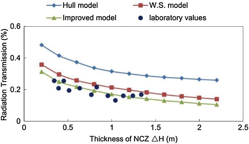
Figure 2: Comparison of several models for radiation transmission
3 Thermal Efficiency Model of a Solar Pond
The thermal efficiency of the solar pond is summarized in a stable state through a flat plate collector analogy by Kooi. The model is improved and a new expression to calculate the thermal efficiency is giver by
where
Replacing
Eqs. (7) and (8) show that the thermal efficiency of a solar pond
Fig. 3 shows the temperature distributions of the LCZ with variable thicknesses of the NCZ and resting days with constant turbidity value and bottom reflectivity. The temperature of the LCZ increased for all the resting days compared with the initial temperature. However, at 40 days of time, the maximum temperature of the LCZ was with a less thickness of NCZ because NCZ thickness negativity strongly influences the absorption of solar energy. If the maximum temperature of LCZ improved with an increase of resting days, the thermal stored in the LCZ decreased quickly for thinner NCZ. Overall, the maximum temperature of the LCZ occurs with thicker NCZ.
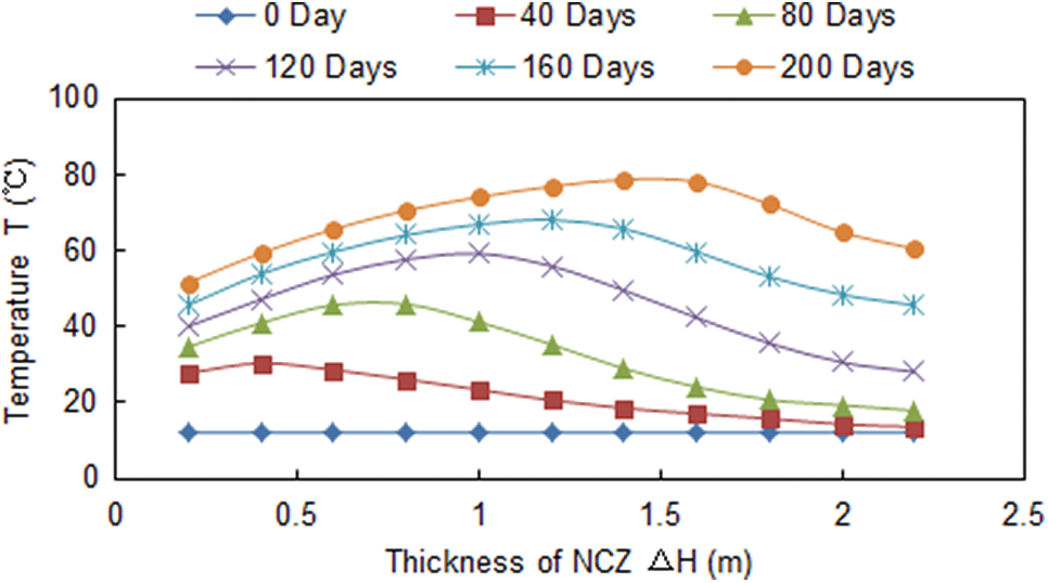
Figure 3: LCZ temperature with thickness of NCZ
Fig. 3 also shows the maximum temperature of the LCZ deviates with the increase of thickness and resting days. In the initial stage of solar pond working, there are more solar radiation reached LCZ and faster temperature raised in LCZ with the decrease of NCZ thickness. In this case, the maximum temperature of LCZ occurs with the less NCZ thickness. However, the LCZ temperature will improve with the increase of resting days. Then the less NCZ thickness will not provide a good thermal insulation effect on higher temperature. Therefore, the greater NCZ thickness, the better thermal insulation effect for the solar pond. In this case, the maximum temperature of LCZ occurs with the greater NCZ thickness. Moreover, if the NCZ thickness is too large, the amount of solar radiation reaching the LCZ will be reduced quickly, which will inhibit the rise of the LCZ temperature. Therefore, the optimum NCZ thickness can effectively improve the LCZ temperature and heat storage performance for the solar pond.
Fig. 4 shows the variations of absorption penetration with increasing bottom reflectivity with a 0.6 m NCZ and 0.3 NTU turbidity. This indicates that the absorption penetration is generally inversely proportional to the bottom reflectivity. Also, zero reflectivity yields the highest absorption penetration because solar radiation that reached the pond bottom was absorbed completely and the heat as then transferred to the LCZ. Finally, the absorption penetration reduced with increased bottom reflectivity because higher bottom reflectivity caused more solar radiation to be reflected to the environment. Overall, a bottom reflectivity value of 1 yields the lowest absorption penetration.
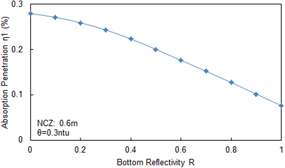
Figure 4: Absorption penetration with the bottom reflectivity
In Fig. 5, the absorption penetration is plotted versus thickness of the NCZ for different selected values of turbidity. Both NCZ thickness and turbidity strongly influenced the absorption penetration. The absorption penetration was inversely proportional to the NCZ thickness and also inversely proportional to the turbidity with a smaller NCZ thickness. However, an opposite trend was found for the relationship of the absorption penetration and turbidity with a larger NCZ thickness. In addition, the heat storage of the salt gradient solar pond is due to the thermal preservation of NCZ. It is difficult for the LCZ to reach a higher temperature for a long-term working solar pond when the NCZ thickness is more less, which is not worth studying for the solar pond. Therefore, the case of a small NCZ thickness is ignored in the article.
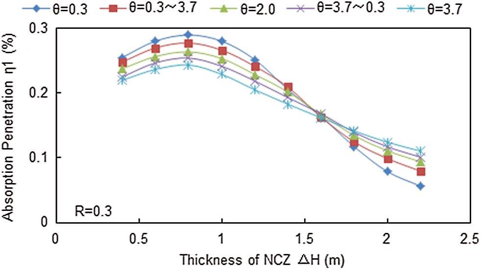
Figure 5: Absorption penetration with NCZ thickness for the different turbidity
Both the turbidity and NCZ thickness play two roles on the absorption penetration of the solar radiation in the solar pond. On the one hand, the increase of turbidity and NCZ thickness can reduce the transmission of solar radiation into the pond, which is harmful to the solar pond. On the other hand, it can also reduce the reflection from the bottom of the pond to the environment, which is beneficial to the solar pond. Absorption penetration have a process of first increasing and then decreasing. When the NCZ thickness exceeds the critical threshold, the absorption penetration will decrease with the increase of NCZ thickness. At this time, the more turbidity of the pond water, the slower decrease rate of the absorption penetration. The reason is that the attenuation coefficient in the solar pond increases with the increase of turbidity. The attenuated solar radiation will be stored in the lower part of the solar pond as the form of thermal energy, and the radiation reflected from the bottom of the pond cannot be lost upward due to the increasing attenuation, which delays the decrease of the absorption penetration. Conversely, the decreasing turbidity can lead to an increasing absorption penetration. There are intersections for absorption penetration between different thickness and turbidity.
Generally speaking, turbidity is an optical effect. It hinders solar transmission and also absorbs solar radiation. A higher turbidity values indicates a stronger ability for hindrance and absorption of solar radiation. In addition, a higher turbidity leads to a higher water reflection for solar radiation entering a pond because of the increased suspended particulate matters in the water. An increased amount of solar radiation is not only hindered and absorbed by turbid water but also reflected multiple times in turbid water. In the case of a small NCZ thickness with low turbidity, the reflection property of the water is weaker so that more solar radiation penetrates the NCZ. However, the reflection of water is stronger in the case of a small NCZ thickness with high turbidity, and more solar radiation is reflected to the environment at the surface but not reflected within the pond, which causes less solar radiation to penetrate the NCZ. The absorption penetration decreases with the increase of turbidity. In addition, solar radiation would be absorbed and reflected multiple times within the NCZ. Overall, higher turbidity with a larger NCZ thickness inhibits bottom reflection of solar energy, which leads an increase in absorption penetration with the increase of turbidity. This scenario is useful for heat storage.
From a thermo-dynamical point, solar radiation is absorbed and reflected on the surface firstly, but not related to the pond. In the case of a small NCZ thickness with a high turbidity, more solar radiation can only be stored at the surface. This heat, with a short-distance to the surface, would also be easily lost to the environment. Therefore, the absorption penetration decreases with an increase in turbidity. When the NCZ is large, highly turbid water can prevent the loss of heat in the LCZ. Therefore, the absorption penetration increases with an increase in turbidity. However, the characteristics above are also reflected for non-uniform turbidity levels in water. When the NCZ is thin, the absorption penetration is higher for an increasing turbidity level with depth compared to when turbidity levels decrease with depth, which is contrary to the case of a thicker NCZ.
Heterogeneous turbidity levels in an actual solar pond are inevitable. Turbidity of pond water generally increases with depth when allowed to rest for extended periods of time, and turbidity of pond water decreases with depth when it is disturbed by external factors such as rain and wind. Therefore, the increasing of up layer turbidity should be prevented and reduced.
4.3 Thermal Conductivity Loss
Fig. 6 shows the variation of thermal conductivity loss with an increasing thickness of NCZ. Three different
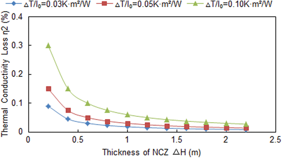
Figure 6: Thermal conductivity loss with an increasing thickness of NCZ
The phenomena are due to two reasons, which are double physical meanings of
However, it is not reasonable to decrease the value of
4.4 Thermal Efficiency of Solar Pond
The calculated data for the thermal efficiency of solar pond are given in Fig. 7 with the reflectivity (R) held constant at 0.3 (a) and 0.8 (b), and turbidity (θ) varied from 0.3–3.7 NTU and was either held constant, increased with depth or decreased with depth. The results show that, the thermal efficiency of the solar pond is directly proportional to the NCZ thickness, bottom reflectivity, and water turbidity. And with the increasing thickness of the NCZ, the thermal efficiency of the solar pond
Figs. 7a and 7b show that the thermal efficiency of solar pond increases first and then decreases with the NCZ thickness. That is because the thermal efficiency of the solar pond is closely related to the NCZ thickness. The thermal insulation performance of NCZ is weaker and the heat of the LCZ is also easily lost to the air when there is a less thickness. So, the thermal efficiency of the solar pond is lower. Moreover, both the thermal insulation performance of the NCZ and the thermal efficiency of the solar pond are gradually improved with the NCZ thickness increases. However, the amount of heat storage in LCZ reduced with the increase of NCZ thickness because of the radiation transmission decreased with the increase of NCZ thickness. Therefore, a critical NCZ thickness threshold is existed. When the NCZ thickness is greater than this critical threshold, the thermal efficiency of the solar pond decreased with the increase of NCZ thickness.
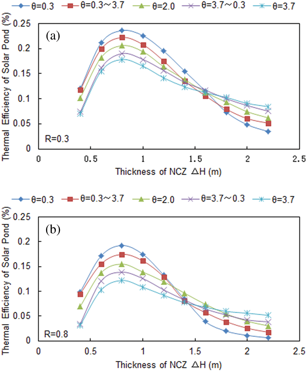
Figure 7: Thermal efficiency with the NCZ thickness for the different turbidity Reflectivity (R) was held constant at 0.3 (a) and 0.8 (b), and turbidity (θ) varied from 0.3–3.7 NTU and was either held constant, increased with depth or decreased with depth. (a) R = 0.3 (b) R = 0.8
Furthermore, Figs. 7a and 7b also show that the thermal efficiency value was lower with a higher bottom reflectivity value for the different selected values of water turbidity. However, in a certain value of bottom reflectivity, thermal efficiency, which is similar to absorption penetration, is not always decreased with the increasing turbidity, but related to NCZ thickness. Overall, the thermal efficiency decreased with an increasing turbidity. When the thickness of the NCZ was less than 0.8 m, there is a general increase in thermal efficiency increased for all cases of turbidity, with the greatest thermal efficiency being the least amount of turbidity. When the NCZ was between 1.0 m–1.5 m thick, the thermal efficiency decreased with increasing turbidity. This is because more solar radiation is absorbed by higher turbidity water while through downward in the pond and less radiation is absorbed by LCZ, which causes both the thermal efficiency and absorption penetration to be reduced. Oppositely, thermal efficiency increased with increasing turbidity when the value of NCZ thickness was greater than 1.5 m because turbidity also hindered the reflected radiation that comes from pond bottom.
This hindrance effect is enhanced with an increasing NCZ thickness, which caused more reflected radiation to be absorbed by the water, and is useful for the absorption of solar radiation in the LCZ. Therefore, there are double effects on turbidity. First, incident solar radiation is hindered with an increasing turbidity, which is resulting in a lower thermal absorption for the LCZ when the NCZ is thin. Second, the reflected radiation from the bottom is reduced with an increasing amount of turbidity, which is resulting in more thermal absorption for the LCZ when the NCZ is thick. When the NCZ thickness is less than 1.5 m, the first effect is more pronounced than the second described effect, and this causes both absorption penetration and thermal efficiency to decrease. On the Contrary, when the thickness of the NCZ is greater than 1.5 m, the second effect is more pronounced than the first one, and the absorption penetration and thermal efficiency are increased. In addition, NCZ thickness is also related to the temperature, turbidity, salinity variation and bottom reflectivity.
In this study, an improved radiation transmission model, which is included multiple reflections and turbidity, has been given. A thermal efficiency model is also provided to analysis the influence of NCZ thickness by simulations.
Absorption penetration and thermal efficiency of the solar pond were reduced with an increase in bottom reflectivity at particular values of turbidity. However, at a particular value of bottom reflectivity, thermal efficiency decreased with increasing turbidity when NCZ thickness was less than 1.5 m and thermal efficiency increased with increasing turbidity when NCZ thickness was greater than 1.5 m. In addition, the NCZ thickness is also related to the temperature, turbidity, salinity variation and bottom reflectivity.
Funding Statement: This research was supported by Natural Science Foundation of Hebei Province (E2019203527) and Department of Education of Hebei Province (ZD2018062).
Conflicts of Interest: The authors declare that they have no conflicts of interest to report regarding the present study.
1. Ridha, B. M., Cong, T. N., Nicolas, G. (2004). Numerical study of transient heat and mass transfer and stability in a salt-gradient solar pond. International Journal of Thermal Sciences, 43(8), 779–790. DOI 10.1016/j.ijthermalsci.2004.02.018. [Google Scholar] [CrossRef]
2. El-Sebaii, A. A. (2005). Thermal performance of a shallow solar-pond integrated with a baffle plate. Applied Energy, 81(1), 33–53. DOI 10.1016/j.apenergy.2004.05.003. [Google Scholar] [CrossRef]
3. Leblanc, J., Akbarzadeh, A., Andrews, J., Lu, H., Golding, P. (2011). Heat extraction methods from salinity-gradient solar ponds and introduction of a novel system of heat extraction for improved efficiency. Solar Energy, 85(12), 3103–3142. DOI 10.1016/j.solener.2010.06.005. [Google Scholar] [CrossRef]
4. Ganesh, S., Arumugam, S. (2016). Performance study of a laboratory model shallow solar pond with and without single transparent glass cover for solar thermal energy conversion applications. Ecotoxicology and Environmental Safety, 134(2), 462–466. DOI 10.1016/j.ecoenv.2016.03.020. [Google Scholar] [CrossRef]
5. Kamran, M., Sher, J. K., Yousuf, J., Muhammad, A. S. (2017). Heat extraction and brine management from salinity gradient solar pond and membrane distillation. Chemical Engineering Research and Design, 118(2), 226–237. DOI 10.1016/j.cherd.2016.12.017. [Google Scholar] [CrossRef]
6. Asaad, H. S., Alireza, A. M., Alasdair, N. C. (2018). Behaviour of a salinity gradient solar pond during two years and the impact of zonal thickness variation on its performance. Applied Thermal Engineering, 130, 1191–1198. DOI 10.1016/j.applthermaleng.2017.11.116. [Google Scholar] [CrossRef]
7. Husain, M., Patil, P. S., Patil, S. R., Samdarshi, S. K. (2003). Optimum size of non-convective zone for improved thermal performance of salt gradient solar pond. Solar Energy, 74(5), 429–436. DOI 10.1016/S0038-092X(03)00157-9. [Google Scholar] [CrossRef]
8. Husain, M., Patil, P. S., Patil, S. R., Samdarshi, S. K. (2004). Combined effect of bottom reflectivity and water turbidity on steady state thermal efficiency of salt gradient solar pond. Energy Conversion and Management, 45(1), 73–81. DOI 10.1016/S0196-8904(03)00123-7. [Google Scholar] [CrossRef]
9. Prasad, R., Rao, D. P. (1996). Estimation of the thickness of the lower convective layer of solar ponds. Renewable Energy, 7(4), 401–407. DOI 10.1016/0960-1481(96)00003-1. [Google Scholar] [CrossRef]
10. Ge, S. C., Sun, W. C., Xie, M. Z. (2005). Numerical simulation of optimum thickness of non-convective zone of solar pond and its maximum efficiency. Journal of Engineering Thermophysics, 26(3), 397–399. [Google Scholar]
11. Hwalader, M. N. A., Brinkworth, B. J. (1981). An analysis of the non-convecting solar pond. Solar Energy, 27(3), 195–204. DOI 10.1016/0038-092X(81)90121-3. [Google Scholar] [CrossRef]
12. Kooi, C. F. (1979). The steady state salt gradient solar pond. Solar Energy, 23(1), 37–45. DOI 10.1016/0038-092X(79)90041-0. [Google Scholar] [CrossRef]
13. Hull, J. R., Liu, K. V., Sha, W. T. (1984). Dependence of ground heat loss upon solar pond size and perimeter insulation. Solar Energy, 33(1), 25–33. DOI 10.1016/0038-092X(84)90113-0. [Google Scholar] [CrossRef]
14. Hull, J. R. (1985). Solar pond ground heat loss to a moving water table. Solar Energy, 35(3), 211–217. DOI 10.1016/0038-092X(85)90100-8. [Google Scholar] [CrossRef]
15. Wang, J., Seyed-Yagoobi, J. (1995). Effect of water turbidity on thermal performance of a salt-gradient solar pond. Solar Energy, 54(5), 301–308. DOI 10.1016/0038-092X(94)00134-Y. [Google Scholar] [CrossRef]
16. Behrooz, M. Z., Mehdi, S. (2017). Exergoeconomic analysis of the salinity-gradient solar pond power plants using two-phase closed thermosyphon: A comparative study. Applied Thermal Engineering, 115(25), 123–133. DOI 10.1016/j.applthermaleng.2016.12.129. [Google Scholar] [CrossRef]
 | This work is licensed under a Creative Commons Attribution 4.0 International License, which permits unrestricted use, distribution, and reproduction in any medium, provided the original work is properly cited. |