| Energy Engineering |
DOI: 10.32604/EE.2021.015354
ARTICLE
Improving Functionality of 2DOF Piezoelectric Cantilever for Broadband Vibration Energy Harvesting Using Magnets
1College of Mechanical and Electrical Engineering, Harbin Engineering University, Harbin, 150001, China
2School of Mechanical and Civil Engineering, Jilin Agriculture Science and Technology University, Jilin, 132101, China
3Beijing Research Institute of Precision Mechatronics and Controls, CALT, Beijing, 100076, China
*Corresponding Author: Shaogang Liu. Email: liu_shaogang@hotmail.com
Received: 12 December 2020; Accepted: 11 March 2021
Abstract: This paper presents a 2DOF nonlinear piezoelectric energy harvester for improving the efficiency of energy harvesting in low frequency range. The device consisted of an L-shaped piezoelectric cantilever with a magnet at the tip of the first beam and two external magnets on the pedestal. The distance between the magnets which generated nonlinear magnetic attraction was adjusted such that the system can exhibit monostable or bistable characteristics. First, the model of this piezoelectric energy harvester was established and the dynamic equation was derived based on the magnetic attractive force. Then, the nonlinear dynamic responses of the system subject to harmonic excitation were explored by a numerical method and validated by experiments. At an excitation level of 4 m/s2 in reverse sweep test for the proposed nonlinear harvester, nearly 240% increase in frequency bandwidth was obtained compared to 2DOF linear one in the first two resonance regions under both monostable and bistable states. Moreover, the nonlinear device yielded a closer frequency band gap between the first two resonance regions. The findings provide insight for the design of a broadband energy harvester when there is nonlinearity using magnets.
Keywords: Piezoelectric; harvester; nonlinear; bandwidth
In recent years, the research of vibration-based environmental energy harvesting has received great attention [1–3]. The methods realizing vibration energy harvesting are mainly electromagnetic [4,5], electrostatic [6] and piezoelectric [7–9] according to the principle of energy conversion. Piezoelectric vibration energy harvesting has the advantages of simple structure, high energy density and miniaturization compared to the other ones. Generally, most of the piezoelectric energy harvesting devices developed by scholars were based on one degree of freedom linear systems. The operating frequency bandwidth is narrow and the power generation performance is optimal only when the external exciting frequency matches the resonance frequency of the system. The power generation performances are weakened rapidly when the excitation frequency deviates. The resonance frequency of piezoelectric energy harvester cannot always match with the external exciting frequency with the characteristics of broadband and time-varying, which greatly limits its application [10,11]. How to make piezoelectric energy harvesting devices have higher energy harvesting efficiency has become one of the urgent problems to be solved.
Most scholars have carried out relevant researches to improve the efficiency of piezoelectric energy harvesting. The methods fall into two categories. The first one achieves the purpose of frequency adjustment by optimizing the mechanical structure [12,13], external load [14] and energy storage circuit [15]. The resonance frequency of the energy harvesting device is matched with the ambient vibration frequency. The other one is to broaden the bandwidth of piezoelectric energy harvester. The energy harvesting structure is optimized to make two or more modes resonance frequencies of the system close to each other to effectively broaden the frequency band [16,17]. Some scholars use nonlinear stiffness to broaden the band of energy harvesting [18,19].
The most common method is the use of nonlinear magnetic force to generate nonlinear stiffness. Stanton et al. modeled a nonlinear energy harvester consisting of a piezoelectric beam with a magnetic end mass. By tuning nonlinear magnetic interactions around the end mass, the frequency response could broaden frequency in either direction [20]. Zhou et al. investigated a broadband piezoelectric energy harvester with a triple-well potential induced by a magnetic field [21]. Fan et al. presented a monostable piezoelectric energy harvester with the stoppers and the magnetically attractive coupling. The device could bring about a wider operating bandwidth and higher output voltage than the linear one under both harmonic excitations and random excitations [22,23]. It is well known that the nonlinear bistable energy harvester has two stable equilibrium positions and one unstable equilibrium position. The main advantage of bistable energy harvester is that it can do high-energy interwell oscillations under the appropriate excitations and show broadband features [24]. Ferrari et al. proposed a nonlinear converter that implemented nonlinearity and bistability by exploiting an attractive magnetic force [25]. Ibrahim et al. derived a magneto elastic beam operating at the transition between monostable and bistable regions. The output voltage and frequency bandwidth were the largest near the transition region which was found to be the optimum range for harvesting energy [26]. Wang et al. proposed a bistable 2DOF piezoelectric energy harvesting with magnetic repulsion to induce nonlinear and the multimodal dynamics for achieving broadband electrical outputs [27]. Compared to the optimal 2DOF linear one, wider bandwidth was achieved in the strong intra-well nonlinear response. But the parameters of this harvester were considered to avoid inter-well dynamics. Lu et al. proposed an E-shape bistable piezoelectric energy harvesting system induced by magnets [28]. When the space between the magnets was decreased to a critical value, the average half power bandwidth could be expanded up to 2.67 Hz, which is 2.34 times higher than the linear one. Zhao et al. analyzed a 2DOF bistable piezoelectric vibration energy harvester with magnetic repulsive force [29].
This paper studies a 2DOF nonlinear energy harvester combining the magnetic attraction which can exhibit monostable and bistable state to solve the problem of limited bandwidth and enhance the environment adaptability of vibration energy harvesting. This paper is organized as follows: Sect. 2deals with the derivation of the analytical model of the piezoelectric energy harvester with magnetic coupling. The structural parameters are determined in Section 3. Section 4 presents a comparison of the simulation results of the nonlinear and conventional 2DOF linear piezoelectric energy harvesters. Experimental set-up is built and experimental results are obtained in Section 5. Section 6 gives a conclusion.
2.1 Exploiting Nonlinearities Using Magnets
The configuration of the proposed 2DOF nonlinear energy harvester is shown in Fig. 1. The energy harvester consists of a rack, an L-shaped cantilever and three magnets. The arrangement of magnets (magnets A, B and C), L-shaped cantilever and the position of the piezoelectric layer (PZT) can be shown in Fig. 1. Magnet C is set at the end of beam I. The magnets A and B are fixed to the rack. The forces of magnets (A, B) on magnet C are attractive forces which are more important to the nonlinear characteristics of energy harvester. The end of the L-shaped cantilever is a mass block. The L-shaped cantilever remains horizontal by upper and lower magnetic forces without base excitation.
One important parameter is the separation horizontal distance d between the magnets (A, B) and the tip magnet C. Another important parameter is the gap distance D between the magnet A and the magnet B shown in Fig. 1. By adjusting the bolts, the distances (d, D) between the magnets can be changed and monostable or bistable type of this harvester can be obtained. When the distance d or D is large, the magnetic force value is almost zero, then the system is approximately a typical 2DOF linear system.
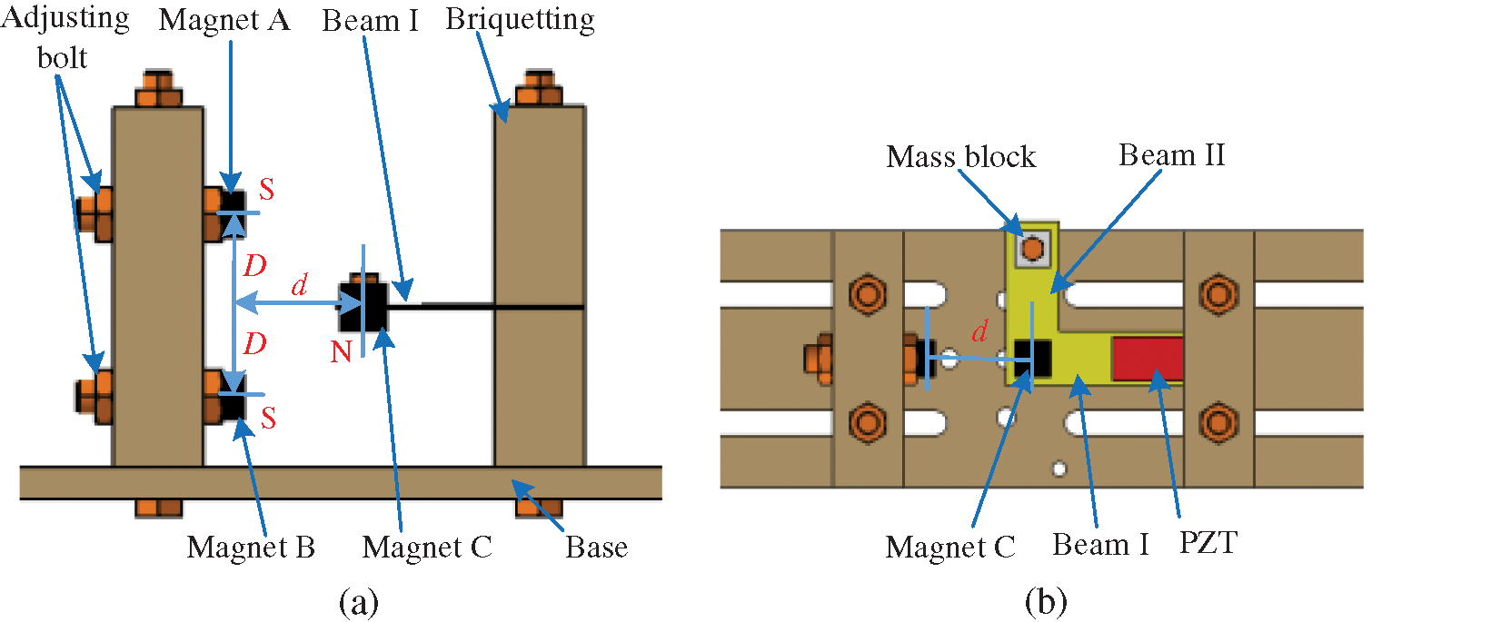
Figure 1: The structure diagram of the 2DOF nonlinear piezoelectric energy harvester using magnets: (a) Front view, (b) Top view
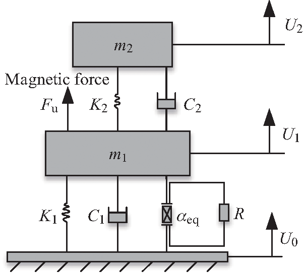
Figure 2: The mechanics model ofthe2DOF nonlinear piezoelectric energy harvester using magnets
Fig. 2 shows the equivalent mechanics model of the 2DOF nonlinear piezoelectric energy harvester. According to the Newton’s second law and the Kirchhoff law, the electromechanical coupling motion equation of the 2DOF nonlinear system can be given by [30]
where
Eq. (1) is transformed into Eq. (2)
Let
Thus Eq. (2) is transformed into state Eq. (3) which can be solved by the Runge-Kutta method.
where
When Fu= 0, the 2DOF linear piezoelectric energy harvester without magnetic is obtained.
As shown in Fig. 1, the nonlinear magnetic force Fu is produced by magnet C at the tip of beam I and two external magnets (A, B) on the pedestal. The nonlinear characteristic of this harvester can be implemented by adjusting the separation distance d horizontally and the gap distance D vertically between magnets A and B.
The potential energy of the magnetic field generated by the two magnets A and B upon magnet C can be given by [31]
where m is the magnetic moment vector.
The magnetic field of dipole A acting on dipole C is given by
where rAC is the vector directed from the magnetic moment source of A to C. MA VA denotes Euclidean norm and ∇ vector is gradient operator. The flux density generated by the magnet B on magnet C can be evaluated by the similar formula. The potential energy of the total magnetic fields can be expressed by
Based on orthogonal decomposition, the magnetic dipole moment vectors (mA, mB, mC) and the vectors (rAC, rBC) can be written as [32]
where rAC represents the vector from the center of magnet A to magnet C. MA and VA represent the magnetization intensity and the volume of magnet A, respectively. The subscripts B and C stands for magnet B and magnet C.
Thus, the magnetic force can be given by
By substituting Eq. (9) into Eq. (3), nonlinear equation of the system can be solved.
3 Determination of Structural Parameters
3.1 The Optimization of 2DOF Linear Harvester
According to Eq. (4), the governing equations can be solved by using the Runge-Kutta method. The voltage amplitude-frequency characteristic curve of 2DOF linear harvester is obtained. The output open voltage and resonance frequency of the harvester are related to the structural parameters. The structural parameters of the 2DOF linear system are optimized to show high voltage at the first two resonance points. Meanwhile, the two peak points should be close to each other. Since the materials of piezoelectric layer and beam are certain because of the experimental conditions, the length of the beam and the mass are adjusted. In order to have a higher voltage at the first two resonance frequencies and a narrow space between the first two resonance frequencies, the parameters are fine-tuned. It is preliminarily determined that the lengths of beam I and beam II are 40 mm and 60 mm, respectively. The masses of m1 and m2 are 9 g and 3 g, respectively. The voltage curves of the 2DOF linear structure under various exciting accelerations are shown in Fig. 3a when the other parameters remain unchanged. The voltage at each frequency point increases with the exciting acceleration. The voltages of the 2DOF linear structure at various masses of m2 under the exciting acceleration of 4 m/s2 are shown in Fig. 3b. The peak voltage at the first resonance point and the distance between peak voltages at the two resonance frequencies are affected by mass m2.
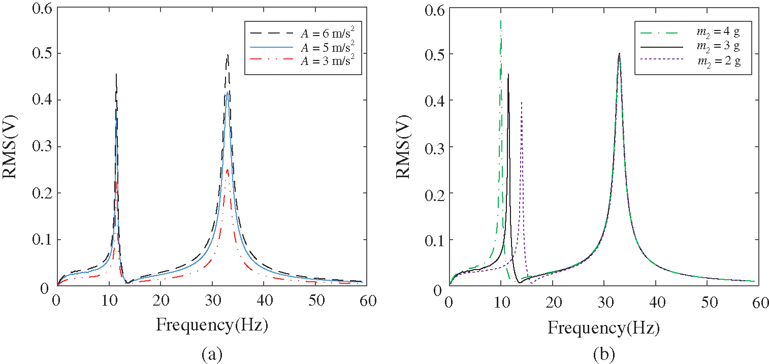
Figure 3: The voltage curves of the 2DOF linear structure under: (a) various A, (b) various m2
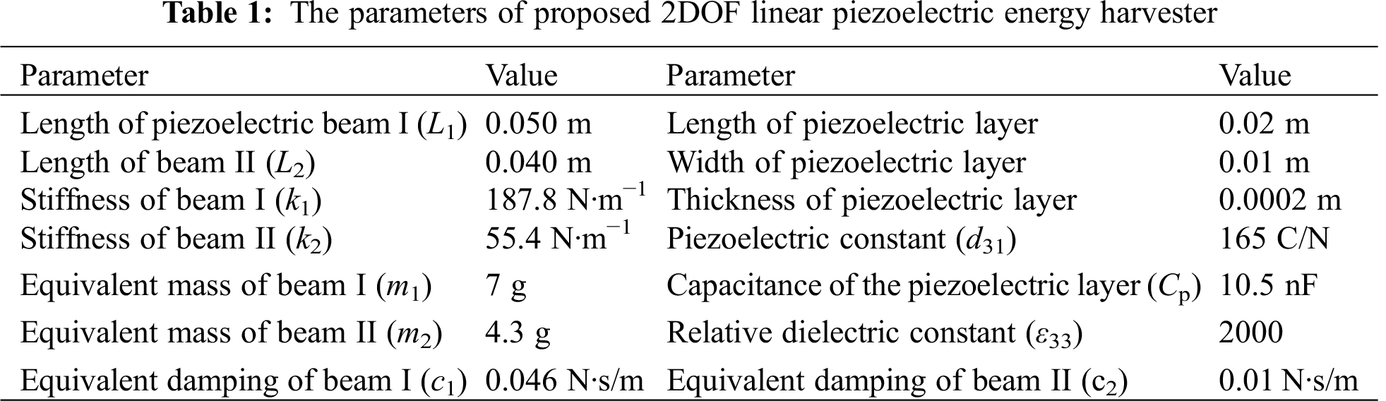
Repeated simulation and debugging, the curve which basically meets the requirements is obtained. The optimized voltage amplitude-frequency characteristic curve under the exciting acceleration of 4 m/s2 is shown in Fig. 4. The effective bandwidth of the 2DOF linear harvester are 1.5 Hz and 2.5 Hz in the first and second resonance regions, respectively, according to the half power bandwidth method. Moreover, the frequency band gap between the two peak voltages (11 Hz, 31 Hz) is 20 Hz. The optimized parameters of the 2DOF nonlinear harvester are shown in Tab. 1.

Figure 4: The output open voltage of optimized 2DOF linear piezoelectric energy harvester
3.2 Analysis of Potential Energy
The nonlinear characteristics (monostable or bistable) of the 2DOF nonlinear energy harvester can be distinguished by the potential energy curves. The total potential energies consist of two parts: the elastic potential energy and the magnetic one. The elastic potential energy can be calculated by the linear stiffness [33]. The magnetic potential can be obtained by Eq. (7). The magnetization vectors (MA, MB, MC) are 1.2 × 10⁶ A∙m–1and the volume of magnets (VA, VB, VC) are 300 × 10–9 m3.
The value of the gap distance D is 8mm. The potential curves under various separation distances d are shown in Fig. 5a. It is obvious that there are two potential wells or one potential well with the values d. If the potential energy curve has only one equilibrium point, the system is monostable and exhibits intrawell nonlinear dynamics. If the potential energy curve has two potential wells, the 2DOF nonlinear energy harvester is bistable. The deeper potential well means larger kinetic energy is needed to carry out the high-energy interwell motion according to the relationship between the kinetic energy and the potential energy. The value of the separation distance d is 9 mm. The potential curves of the 2DOF nonlinear energy harvester under various gap distance D are shown in Fig. 5b. Magnetic attraction has little effect on the vibration when the gap distance D is 20 mm. Then the system is approximately a linear structure. When D changes from large to small, the potential energy curve changes from one equilibrium point to two equilibrium points and then returns to one equilibrium point.
The value of d is set as 11 mm and the gap distance D is set as 8 mm. The system is a monostable configuration in this case. The value of d is set as 9 mm and the gap distance D is set as 8 mm to ensure that the system is a bistable system. The barrier is not too high and the system easily exhibits interwell nonlinear dynamics between two potential wells under lower exciting acceleration. This nonlinear harvester is more suitable to harvest vibration energy in lower intensity vibration environment.

Figure 5: Potential energy of the 2DOF nonlinear piezoelectric energy harvester: (a) various d, (b) various D
4.1 Monostable Configuration under Sinusoidal Excitations
In this part, numerical simulations are carried out to study the characteristic response of the 2DOF monostable system under harmonic excitation. The governing Eq. (3) and linear Eq. (4) are solved. The distances d and D is 11 mm and 8 mm, respectively. They are determined in Part 3 to ensure that the system is a monostable one. Other parameters are shown in Tab. 1. Linearly decreasing frequency excitation simulations are performed from 60 Hz to 1 Hz.
The root-mean-square (RMS) voltages of linear and monostable harvesters under the exciting acceleration of 4 m/s2 are shown in Fig. 6. The monostable system exhibits nonlinear characteristics in the first resonance region, though the peak voltage is smaller than the linear system. The voltage curve of the second region is approximately linear. The first effective bandwidth is from 38 Hz to 26 Hz and the second effective bandwidth is from 16.5 Hz to 13.5 Hz according to the half power bandwidth method. The total effective bandwidth of this monostable system in the first two resonance regions is greater than the linear one. Meanwhile, the space between the two peaks of the first two resonance regions is shorter than the linear one.

Figure 6: Voltage responses of the 2DOF monostable and linear harvesters (d = 11 mm, D = 8 mm)
Fig. 7 shows the voltage responses of this monostable system under various masses m2 (4.3 g, 3.5 g and 3 g). The peak voltage in the second resonance frequency region is affected by different masses, but the voltage response bandwidth shows the broadband characteristics in the first resonance frequency region.

Figure 7: Voltage responses of the 2DOF monostable harvester under different masses m2
4.2 Bistable Configuration under Sinusoidal Excitations
In this part, numerical simulations are carried out to study the characteristic response of the 2DOF bistable energy harvester under harmonic excitation. The exciting acceleration A is 4 m/s2 and the frequency
Fig. 8 shows the voltage responses of the 2DOF bistable and linear harvesters. The 2DOF bistable system exhibits nonlinear dynamics in two resonance regions. In the first resonance region, the voltage fluctuates due to the chaos. The bistable resonance frequency regions are latter than the linear one because of the magnetic attractive force. The motion properties of these frequency points (13 Hz, 30 Hz) can be shown in Fig. 9.

Figure 8: Voltage responses of the 2DOF bistable and linear harvesters (d = 9 mm, D = 8 mm)
Both the bistable and linear systems exhibit small periodic motions when the frequency f = 60–40 Hz outside the first resonance interval shown in Fig. 8. The system operates in high energy orbit in the first resonance region at f = 30 Hz shown in Fig. 9b. The voltage produced by the bistable harvester is much higher than the linear one. Both the bistable and linear harvesters return to small periodic motions during f = 27 Hz–20 Hz outside the first resonance interval shown in Fig. 8. As the frequency decreases, the system enters the second resonance region. The bistable harvester exhibits intra-well nonlinear dynamics around one equilibrium point at f = 13 Hz shown in Fig. 9a.
The effective bandwidth range of the bistable can be extended to 35.5–28.5 Hz in the first resonance region and 16.5–13 Hz in the second resonance region. Though the 2DOF bistable harvester does not exhibit interwall motions in the second resonance region, the system also exhibits broadband characteristics in the first two resonance regions. Moreover, the frequency band gap between the two peaks of the first two resonance regions is 17 Hz, which is 3 Hz closer than the linear one.

Figure 9: Displacement phase portraits of the bistable and linear harvesters at various exciting frequencies: (a) f = 13 Hz, (b) f = 30 Hz
The equivalent mass of beam has a great influence on the system. As can be seen from Eq. (3), the system response is affected by the mass ratio μ. Fig. 10 shows the voltage responses under different equivalent masses of m2 = 4.9 g and m2 = 4.3 g. The peak of the first resonance region increases and the peak of the second resonance region decreases when the mass m2 increases only 0.6 g. In addition, the frequency band gap between the first two resonance regions expands to 25 Hz. In a word, the system also shows broadband characteristics in the first two resonance regions.

Figure 10: Voltage responses under various masses at m2 = 4.9 g and 4.3 g
5 Prototype and Experimental Analysis
The experimental system consists of four parts and they are the 2DOF nonlinear piezoelectric cantilever, exciting system, signal acquisition and processing systems, respectively. The prototype of 2DOF nonlinear harvester with magnetic coupling is shown in Fig. 11. The 2DOF cantilever is made of brass and the frame is made of acrylic material. The piezoelectric layer is attached to the beam I. The distances between the magnets (A, B and C) can be adjusted by the adjustable plates. The prototype is a 2DOF linear structure when the magnets A, B and C are replaced by a mass block.
The main experimental devices are shown in Fig. 12. The experimental devices include signal generator YE1311, power amplifier YE5871, shaker JZK-5, accelerator DH151, dynamic signal analyzer DH5939D, oscilloscope DS5202CAand computer so on. In the process of experiments, the signal generator can produce signals of different intensity with frequency bandwidth of 0–100 Hz. The harmonic base excitation signals are amplified by the power amplifier. The 2DOF device generates electricity under vibration. The output voltage of the piezoelectric part is determined by an oscilloscope. The acceleration at the base of the device is measured by an accelerator. Then the date is recorded by the PC through the dynamic signal analyzer.

Figure 11: Experimental device of the 2DOF nonlinear piezoelectric energy harvester

Figure 12: The main experimental equipment
5.2 Experimental Analysis of 2DOF Monostable Device
The base acceleration value is 4 m/s2 and the exciting frequency decreases in the reverse way. The frequency sweep experiments of the linear and monostable devices were carried out, respectively. The 2DOF linear device can be obtained by replacing all the magnets with mass blocks. The distances d and D between the magnets are determined in Part 3 to ensure that the device is a monostable one. The experimental results of the RMS voltage are shown in Fig. 13. The monostable device exhibits strong nonlinear characteristics in the first resonance region and is approximately linear in the second resonance region. The effective bandwidth of the monostable device is 10 Hz (frequency range 40 Hz–30 Hz) in the first resonance region and the effective bandwidth of the monostable device is 2 Hz (frequency range 13.5 Hz–11.5 Hz) in the second resonance region according to the half power bandwidth method. But the effective bandwidth of the linear are 2.2 Hz and 1.3 Hz in the first and second resonance regions, respectively. The total effective bandwidth of this monostable device is 3.4 times higher than the linear one. For the 2DOF linear device, the distance between the first two resonance points (12 Hz, 33 Hz) is 21 Hz. The frequency band gap between the two peaks of the first two resonance regions (13 Hz, 30 Hz) is 17 Hz which is 4 Hz closer than the linear one. The presented simulation results are validated by experimental results.
Fig. 14 shows the voltage curve of the 2DOF monostable device recorded by oscilloscope at different frequencies of 13 Hz and 30 Hz. The voltage curve generated by the piezoelectric layer is sinusoidal when small errors are ignored. The average value of the peak voltage is 0.46 V and the recording time length is 100 ms between adjacent dotted lines at f = 13 Hz. The average value of the peak voltage is 0.36 V and the recording time length is 50 ms between adjacent dotted lines at f = 30 Hz.

Figure 13: Experimental results of the voltage values of the 2DOF monostable and linear devices

Figure 14: Voltage curves of the 2DOF monostable device recorded by oscilloscope at different frequencies: (a) 13 Hz, (b) 30 Hz
5.3 Experimental Analysis of 2DOF Bistable Device
The bistable experimental conditions were the same as the monostable one. Adjusting the magnet spacing to make sure it is a bistable device. The experimental results of the RMS voltage are shown in Fig. 15. The bistable device begins to enter the first resonance region when the exciting frequency is 40 Hz. As the frequency continues to decrease, the voltage fluctuates because of chaos. The bistable device begins to enter the large period motion state at 33 Hz. The high output voltage continues until 30 Hz. Then it goes into small motion. The first resonance region ends. The bistable device begins to enter the second resonance region at 19 Hz with the frequency decreasing. This process continues until 13 Hz. Then the second resonance region ends.
Fig. 16 shows the voltage curve of the 2DOF bistable device recorded by the oscilloscope at different frequencies f = 14.1 Hz and f = 31.1 Hz. The recording time length are 100 ms and 2 s between adjacent dotted lines, respectively. The average peak voltages of Figs. 16a and 16b are 0.35 V and 0.43 V, respectively. In order to show the voltage curve of the device in steady state, the recording time of Fig. 16b between adjacent dotted lines is much longer than Fig. 16a.

Figure 15: Experimental results of the voltage values of 2DOF bistable and linear devices

Figure 16: Experimental voltage curves of the 2DOF bistable device recorded by the oscilloscope at different frequencies: (a) f = 14.1 Hz, (b) f = 31.1 Hz
The effective bandwidth of the bistable device is 8 Hz (frequency range 37.5–29.5 Hz) in the first resonance region and the effective bandwidth of the bistable device is 4 Hz (frequency range 17.5–13.5 Hz) in the second resonance region according to the half power bandwidth method. The total effective bandwidth of this bistable device is 3.4 times higher than the linear one. For the 2DOF bistable device, the frequency band gap between the two peaks of the first two resonance regions is 16 Hz which is 5 Hz closer than the linear one.
Fig. 15 and Fig. 8 are compared. Tab. 2 shows the comparison of the relative errors between the theoretical and experimental results. There is a deviation between the theoretical value and the experimental value. The maximum error of linear peak voltage at first resonance point is 12.5%. The maximum error of bistable peak voltage in first resonance region is 25%. The main reason is that the separation distance d and the gap distance D have a great effect on magnetic force. A very small deviation makes a big error. In practice, the distance deviations are inevitable due to the precision of the instrument. In addition, the theoretical magnetic force model cannot accurately describe the value of the magnetic force during the motion.
Fig. 17 shows the load resistance voltage and the output power for f = 33 Hz of the bistable device. The voltage across the external load will gradually increase as the load resistance increases. But the voltage will eventually converge to open circuit voltage of the system. The output power of the system increases with the external load resistance. But when the load resistance increases to a critical value, the power will decrease. It can be seen from Fig. 17, at the first resonance region the maximum output power of the bistable device is 0.075 μW. And the corresponding load resistance is 421 kΩ. At this time, the external load resistance is approximately equal to the equivalent impedance of the piezoelectric element under the external excitation frequency. Although the power is small, if the capacitance of the piezoelectric plate is large, the 2DOF bistable device will have a higher energy efficiency in both resonance regions.
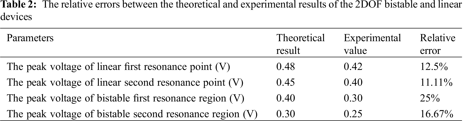

Figure 17: The load resistance voltage and the output power for ω = 33 Hz
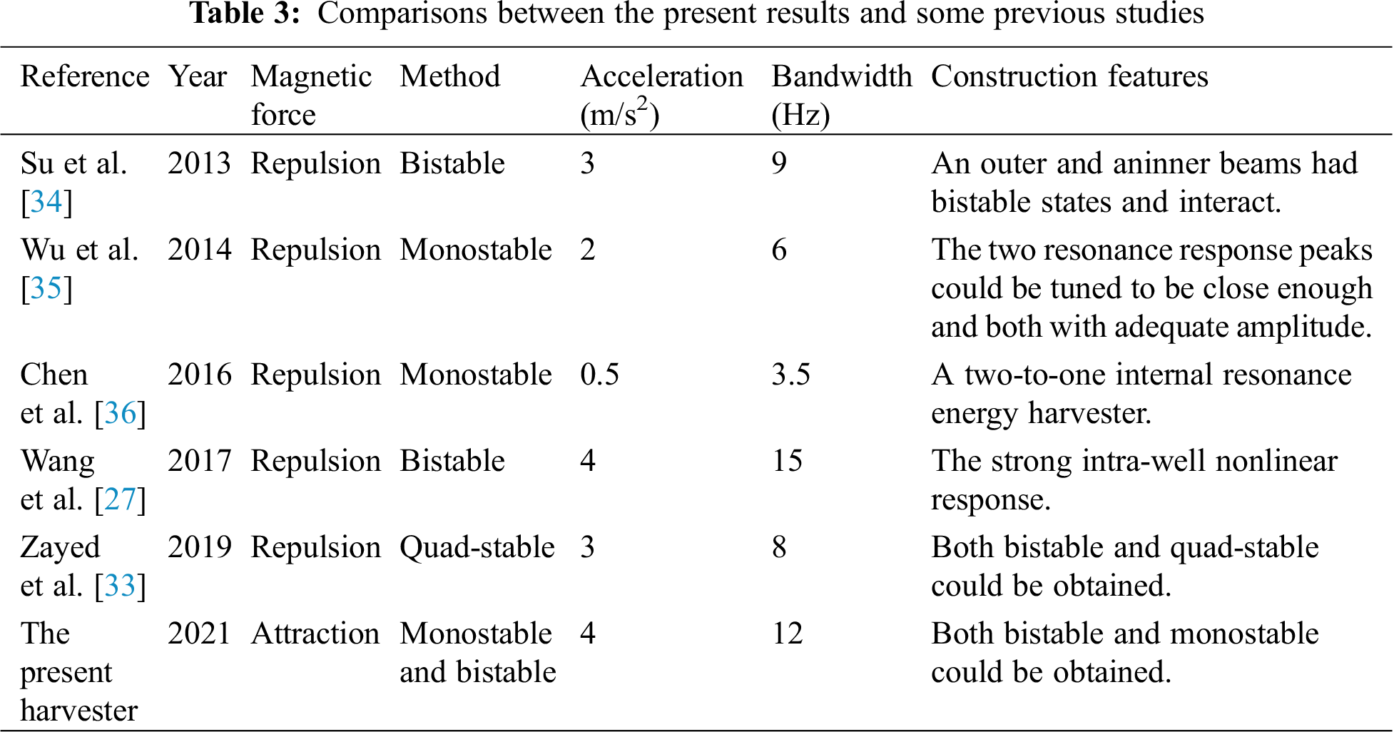
Tab. 3 shows comparisons between the present results and some previous studies of 2DOF piezoelectric energy harvester with magnetic coupling for wide bandwidth. Magnetic force plays a very important role in nonlinear behavior. Broadband characteristics can be obtained using different methods such as monostable, bistable and quad-stable. This present harvester has wider bandwidth under both monostable and bistable state.
In this paper, a 2DOF nonlinear piezoelectric energy harvester with magnetic coupling was developed to increase the frequency bandwidth and narrow frequency band gap between the first two resonance regions for improving the efficiency of energy harvesting from low frequency vibrations.
By mounting and adjusting magnet C at the tip of beam I and two external magnets on the pedestal, the system could exhibit monostable or bistable characteristics. The model of this harvester was established and the dynamic equation was derived on the basis of the formula for the magnetic attractive force about three magnets. The comparisons of voltage output response at different excitation frequencies for 2DOF linear and nonlinear piezoelectric energy harvesters can be obtained by simulation. By performing experimental studies, the presented simulation results were validated by experimental results. The total effective bandwidth is 3.4 times higher than the linear one for both the monostable and bistable states of this nonlinear harvester. The frequency band gap between the two peaks of the first two resonance regions is 4 Hz closer than the linear one for the monostable state and 5 Hz closer than the linear one for the bistable state. The motions of the bistable device were more complex than the monostable one because it contained small period, large period and chaotic motions. The results showed that both the monostable and bistable states of this nonlinear harvester achieved wider operating frequency bandwidth in first two resonance regions and yielded a closer frequency band gap between the first two resonance regions. The broadband characteristics were affected by structural parameters. The development of 2DOF nonlinear piezoelectric energy harvester with magnetic coupling will provide an insight for designing a device for broadband vibration energy harvesting.
Funding Statement: This work is supported by the National Natural Science Foundation of China (No. 51675111).
Conflicts of Interest: The authors declare that they have no conflicts of interest to report regarding the present study.
1. Sun, C. H., Shang, G. Q., Tao, Y. Y., Li, Z. R. (2012). A review on application of piezoelectric energy harvesting technology. Advanced Materials Research, 516–517, 1481–1484. DOI 10.4028/www.scientific.net/AMR.516-517.1481. [Google Scholar] [CrossRef]
2. Shaikh, F. K., Zeadally, S. (2016). Energy harvesting in wireless sensor networks: A comprehensive review. Renewable and Sustainable Energy Reviews, 55(3), 1041–1054. DOI 10.1016/j.rser.2015.11.010. [Google Scholar] [CrossRef]
3. Kumar, A., Kiran, R., Chauhan, V. S., Kumar, R., Vaish, R. (2018). Piezoelectric energy harvester for pacemaker application: a comparative study. Materials Research Express, 5(7), 075701. DOI 10.1088/2053-1591/aab456. [Google Scholar] [CrossRef]
4. Wang, P. H., Dai, X. H., Fang, D. M., Zhao, X. L. (2007). Design, fabrication and performance of a new vibration-based electromagnetic micro power generator. Microelectronics Journal, 38(12), 1175–1180. DOI 10.1016/j.mejo.2007.10.002. [Google Scholar] [CrossRef]
5. Zhao, D., Liu, S., Xu, Q., Sun, W., Wang, T. et al. (2018). Theoretical modeling and analysis of a 2-degree-of-freedom hybrid piezoelectric-electromagnetic vibration energy harvester with a driven beam. Journal of Intelligent Material Systems and Structures, 1–12. [Google Scholar]
6. Mitcheson, P. D., Miao, P., Stark, B. H., Yeatman, E. M., Holmes, A. S. et al. (2004). MEMS electrostatic micro power generator for low frequency operation. Sensors and Actuators A: Physical, 115(2–3), 523–529. DOI 10.1016/j.sna.2004.04.026. [Google Scholar] [CrossRef]
7. Dutoit, N. E., Wardle, B. L. (2007). Experimental verification of models for micro fabricated piezoelectric vibration energy harvesters. AIAA Journal, 45(5), 1126–1137. DOI 10.2514/1.25047. [Google Scholar] [CrossRef]
8. Chew, Z., Li, L. (2010). Design and characterisation of a piezoelectric scavenging device with multiple resonant frequencies. Sensors and Actuators A: Physical, 162(1), 82–92. DOI 10.1016/j.sna.2010.06.017. [Google Scholar] [CrossRef]
9. Zamanian, M., Javadi, S., Firouzi, B., Hosseini, S. A. A. (2018). Modeling and analysis of power harvesting by a piezoelectric layer coated on an electrostatic ally actuated micro cantilever. Materials Research Express, 5(12), 125502. DOI 10.1088/2053-1591/aadf15. [Google Scholar] [CrossRef]
10. Ramlan, R., Brennan, M. J., Mace, B. R., Kovacic, I. (2010). benefits of a non-linear stiffness in an energy harvesting device. Nonlinear Dynamics, 59(4), 545–558. DOI 10.1007/s11071-009-9561-5. [Google Scholar] [CrossRef]
11. Cottone, F., Vocca, H., Gammaitoni, L. (2009). Nonlinear energy harvesting. Physical Review Letters, 102(8), 080601. DOI 10.1103/PhysRevLett.102.080601. [Google Scholar] [CrossRef]
12. Zhang, G., Gao, S., Liu, H. (2016). A utility piezoelectric energy harvester with low frequency and high-output voltage: theoretical model, experimental verification and energy storage. AIP Advances, 6(9), 137–156. [Google Scholar]
13. Sun, Y., Gao, X., Hua, W., Chen, Z., Yang, Z. (2018). A wideband ultrasonic energy harvester using 1-3 piezoelectric composites with non-uniform thickness. Applied Physics Letters, 112(4), 043903. DOI 10.1063/1.5012822. [Google Scholar] [CrossRef]
14. Cammarano, A., Burrow, S. G., Barton, D. A. W., Carrella, A., Clare, L. R. (2010). Tuning a resonant energy harvester using a generalized electrical load. Smart Materials and Structures, 19(5), 055003. DOI 10.1088/0964-1726/19/5/055003. [Google Scholar] [CrossRef]
15. Shu, Y. C., Lien, I. C. (2006). Analysis of power output for piezoelectric energy harvesting systems. Smart Materials and Structures, 15(6), 1499–1512. DOI 10.1088/0964-1726/15/6/001. [Google Scholar] [CrossRef]
16. Liu, S., Cheng, Q., Dan, Z., Feng, L. (2016). Theoretical modeling and analysis of two-degree-of-freedom piezoelectric energy harvester with stopper. Sensors and Actuators A: Physical, 245, 97–105. DOI 10.1016/j.sna.2016.04.060. [Google Scholar] [CrossRef]
17. Zhou, S., Yan, B., Inman, D. (2018). A novel nonlinear piezoelectric energy harvesting system based on linear-element coupling: design, modeling and dynamic analysis. Sensors, 18(5), 1492. DOI 10.3390/s18051492. [Google Scholar] [CrossRef]
18. Hajati, A., Kim, S. G. (2011). Ultra-wide bandwidth piezoelectric energy harvesting. Applied Physics Letters, 99(8), 083105. DOI 10.1063/1.3629551. [Google Scholar] [CrossRef]
19. Gafforelli, G., Corigliano, A., Xu, R., Kim, S. G. (2014). Experimental verification of a bridge-shaped, nonlinear vibration energy harvester. Applied Physics Letters, 105(20), 203901. DOI 10.1063/1.4902116. [Google Scholar] [CrossRef]
20. Stanton, S. C., Mcgehee, C. C., Mann, B. P. (2009). Reversible hysteresis for broadband magnetopiezoelastic energy harvesting. Applied Physics Letters, 95(17), 174103. DOI 10.1063/1.3253710. [Google Scholar] [CrossRef]
21. Zhou, S., Cao, J., Inman, D. J., Jing, L., Liu, S. et al. (2014). Broadband tristable energy harvester: Modeling and experiment verification. Applied Energy, 133(5), 33–39. DOI 10.1016/j.apenergy.2014.07.077. [Google Scholar] [CrossRef]
22. Fan, K., Tan, Q., Zhang, Y., Liu, S., Cai, M. et al. (2018). A monostable piezoelectric energy harvester for broadband low-level excitations. Applied Physics Letters, 112(12), 123901. DOI 10.1063/1.5022599. [Google Scholar] [CrossRef]
23. Fan, K., Tan, Q., Liu, H., Zhang, Y., Cai, M. (2019). Improved energy harvesting from low-frequency small vibrations through a monostable piezoelectric energy harvester. Mechanical Systems and Signal Processing, 117, 594–608. DOI 10.1016/j.ymssp.2018.08.001. [Google Scholar] [CrossRef]
24. Erturk, A., Inman, D. J. (2011). Broadband piezoelectric power generation on high-energy orbits of the bistable Duffing oscillator with electromechanical coupling. Journal of Sound and Vibration, 330(10), 2339–2353. DOI 10.1016/j.jsv.2010.11.018. [Google Scholar] [CrossRef]
25. Ferrari, M., Baù, M., Guizzetti, M., Ferrari, V. (2011). single-magnet nonlinear piezoelectric converter for enhanced energy harvesting from random vibrations. Sensors and Actuators A: Physical, 172(1), 287–292. DOI 10.1016/j.sna.2011.05.019. [Google Scholar] [CrossRef]
26. Ibrahim, A., Towfighian, S., Younis, M. I. (2017). Dynamics of transition regime in bistable vibration energy harvesters. Journal of Vibration and Acoustics, 139(5), 025031. DOI 10.1115/1.4036503. [Google Scholar] [CrossRef]
27. Wang, H., Tang, L. (2017). Modeling and experiment of bistable two-degree-of-freedom energy harvester with magnetic coupling. Mechanical Systems and Signal Processing, 86, 29–39. DOI 10.1016/j.ymssp.2016.10.001. [Google Scholar] [CrossRef]
28. Lu, Q., Scarpa, F., Liu, L., Leng, J., Liu, Y. (2018). An e-shape broadband piezoelectric energy harvester induced by magnets. Journal of Intelligent Material Systems and Structures, 29(11), 2477–2491. DOI 10.1177/1045389X18770871. [Google Scholar] [CrossRef]
29. Zhao, D., Gan, M., Zhang, C., Wei, J., Liu, S. et al. (2018). Analysis of broadband characteristics of two degree of freedom bistable piezoelectric energy harvester. Materials Research Express, 5(8), 085704. DOI 10.1088/2053-1591/aad491. [Google Scholar] [CrossRef]
30. Tang, L., Yang, Y. (2012). A multiple-degree-of-freedom piezoelectric energy harvesting model. Journal of Intelligent Material Systems and Structures, 23(14), 1631–1647. DOI 10.1177/1045389X12449920. [Google Scholar] [CrossRef]
31. Stanton, S. C., Mcgehee, C. C., Mann, B. P. (2010). Nonlinear dynamics for broadband energy harvesting: Investigation of a bistable piezoelectric inertial generator. Physica D: Nonlinear Phenomena, 239(10), 640–653. DOI 10.1016/j.physd.2010.01.019. [Google Scholar] [CrossRef]
32. Lan, C., Qin, W. (2017). Enhancing ability of harvesting energy from random vibration by decreasing the potential barrier of bistable harvester. Mechanical Systems and Signal Processing, 85, 71–81. DOI 10.1016/j.ymssp.2016.07.047. [Google Scholar] [CrossRef]
33. Zayed, A. A. A., Assal, S. F. M., Nakano, K., Kaizuka, T., El-Bab, A. (2019). Design procedure and experimental verification of a broadband quad-stable 2-DOF vibration energy harvester. Sensors, 19(13), 2893. DOI 10.3390/s19132893. [Google Scholar] [CrossRef]
34. Su, W. J., Zu, J., Zhu, Y. (2013). Design and development of a broadband magnet-induced dual-cantilever piezoelectric energy harvester. Journal of Intelligent Material Systems and Structures, 25(4), 430–442. DOI 10.1177/1045389X13498315. [Google Scholar] [CrossRef]
35. Wu, H., Tang, L., Yang, Y., Soh, C. K. (2014). Development of a broadband nonlinear two-degree-of-freedom piezoelectric energy harvester. Journal of Intelligent Material Systems and Structures, 25(14), 1875–1889. DOI 10.1177/1045389X14541494. [Google Scholar] [CrossRef]
36. Chen, L. Q., Jiang, W. A., Panyam, M., Daqaq, M. F. (2016). A broadband internally-resonant vibratory energy harvester. Journal of Vibration and Acoustics, 138(6), 061007.1–061007.10. [Google Scholar]
 | This work is licensed under a Creative Commons Attribution 4.0 International License, which permits unrestricted use, distribution, and reproduction in any medium, provided the original work is properly cited. |