| Energy Engineering |
DOI: 10.32604/EE.2021.015751
ARTICLE
Coal Seam Permeability Improvement and CBM Production Enhancement by Enlarged Borehole: Mechanism and Application
1China Pingmei Shenma Group, State Key Laboratory Coking Coal Exploitat & Comprehens, Pingdingshan, 467000, China
2Key Laboratory of Coal Methane and Fire Control, Ministry of Education, China University of Mining & Technology, Xuzhou, 221116, China
3National Engineering Research Center for Coal Gas Control, China University of Mining & Technology, Xuzhou, 221116, China
*Corresponding Author: Peng Chu. Email: chupeng1994@126.com
Received: 11 January 2021; Accepted: 01 April 2021
Abstract: The permeability is a key factor to determine the efficiency of coalbed methane (CBM) production. The borehole enlargement technology using hydraulic and mechanical measures to cut coal is an effective method to increase the coal seam permeability and improve the efficiency of gas drainage. Reasonable design of the layout of boreholes is the prerequisite for efficient and economical gas drainage. In this paper, based on the strain-softening model, the stress and permeability model of the coal seam around the enlarged borehole was built, and based on the dual-medium model, the gas migration model in the coal seam was established. Then the borehole enlargement gas drainage engineering of E9/10 coal seam in Pingdingshan No. 8 coal mine was simulated by using COMSOL Multiphysics software. The distribution of stress and permeability in the coal seam around a borehole was analyzed, and the reasonable borehole radius of 0.25 m and reasonable borehole spacing of 6 m were determined. Finally, in Pingdingshan No. 8 coal mine, field application was carried out in E9/10 coal seam-21070 working face from the high-level gas drainage roadway. The results show that the actual average coal slag discharge rate is 77.82%, which achieved borehole enlargement. The natural gas flow rate from an enlarged borehole is 2.3–7.3 times that of a normal borehole, and the influence range of enlarged boreholes is more than 6 m. The average gas drainage concentration of a group of enlarged boreholes is about 42%, and the average gas drainage amount is about 0.53 m3/min. After two months of gas extraction, the outburst risk in this area was eliminated, which provides a guarantee for safe coal mining.
Keywords: CBM production; gas extraction; enlarged borehole; permeability improvement; numerical simulation; field application
Coalbed methane (CBM), as a co-product of coal, is a rich high-quality clean energy, and also a major hazard in the mining industry [1–3]. Coal seam gas accident is a major factor for threatening coal mine safety production [4–6]. Gas drainage is an important method to solve gas accidents and also furnish efficient energy [5,7]. Coal seam permeability is a key factor that determines the efficiency of CBM production [8,9]. However, China’s coal seam permeability is generally low, and the gas drainage is difficult [10,11]. Therefore, it is very essential to increase the coal seam permeability when gas drainage is performed.
Drilling enlarged boreholes using hydraulic and mechanical measures is an effective method to increase the permeability of the coal seam. Enlarged borehole gas drainage enhancement technology has two forms: cross-seam borehole and in-seam borehole. An in-seam borehole is to drill the cave along the coal seam to extract gas, and the cross-seam borehole is to drill caves from the rock roadway to penetrate the coal seam, which is safer and more stable than the in-seam borehole. In underground engineering, after the coal is excavated, the stress around the hole is redistributed. When the strength of the coal body is not enough to bear the redistributed stress, the coal will be destroyed. Researches have shown that after the coal is damaged, the permeability can increase by tens to several thousand times [12,13].
In recent years, borehole enlarged technology using the hydraulic and mechanical method, especially cross-seam boreholes, has been widely used in coal mines in China [14–16], which can increase the gas flow rate and the gas drainage concentration, lessen the time of gas extraction, and provide a guarantee for coal mining. However, the distribution of permeability around the enlarged borehole is not clear. Knowing the permeability distribution can not only directly evaluate the effect of the borehole enlarged engineering on improving coal permeability, but also provide guidance for the determination of borehole parameters, such as borehole radius and borehole spacing. Reasonable design of the boreholes is the prerequisite for efficient and economical gas drainage, which is of great significance for CBM production.
In this paper, the stress and permeability model after drilling the enlarged borehole was established based on the strain-softening model, and the gas migration model in the coal seam was built based on the dual-medium model. The controlling equations are solved using COMSOL Multiphysics numerical simulation software. The gas extraction design of E9/10 coal seam in Pingdingshan No. 8 coal mine was determined by simulation. And the field application was implemented from the high-level gas drainage roadway to the E9/10 coal seam. Results show that the gas extraction design is reasonable and the borehole enlarged technology improves the drainage efficiency and gas concentration, which achieved the safety, economic, and environmental priorities for coal mining in the area.
2.1.1 The Stress Distribution around the Borehole
Coal is a kind of elastoplastic material, which will show softening characteristics when the stress exceeds its peak stress. The coal stress around the borehole will be redistributed after excavation. When the load of the coal body around the borehole exceeds its strength, the coal body enters a plastic state or even breaks completely. Hoek et al. [17] studied the post-peak mechanical properties of coal and rock, and found that coal and rock exhibited three mechanical properties: brittleness, strain softening, and ideal plasticity in the post-peak stage. Therefore, Gonzalez-Cao et al. [18] divided the mechanical models into three types: the elastic-brittle model, the strain-softening model, and the ideal elastic-plastic model, as shown in Fig. 1. The strain-softening model is the most commonly used in engineering, while the elastic-brittle model and the ideal elastic-plastic model are two special forms. Therefore, the strain-softening model is used to describe the coal mechanical properties in this study. Based on the strain-softening model, the entire stress-strain curve of coal can be divided into an elastic stage, a softening stage, and a residual stage. Correspondingly, in the coal seam, an elastic zone, a plastic zone, and a failure zone are formed around the borehole, as shown in Fig. 1.
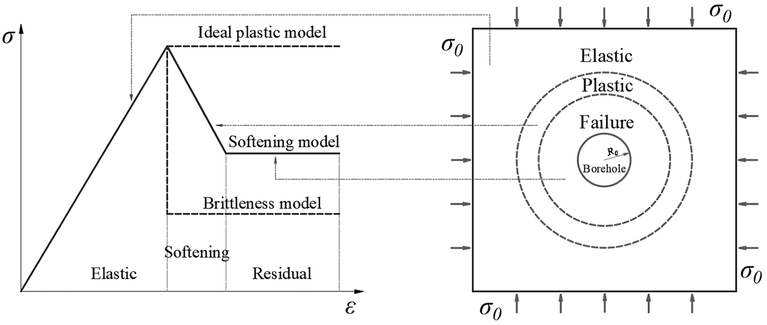
Figure 1: Mechanical models and stress distribution around a borehole
The equivalent plastic shear strain can be used as a softening parameter to describe the strain-softening process of coal [19,20]:
where
The strain-softening is the process of losing the cohesive force when the friction angle is constant. The cohesion decreases linearly with the increase of the equivalent plastic shear strain. Under plastic conditions, the cohesion on the whole stress-strain curve can be expressed as follows [21]:
where c is the cohesion, c0 is the initial cohesion, cr is the residual cohesion, and
The Mohr–Colomb (M–C) strength theory can better describe the strength characteristics of geotechnical materials, so it has been widely used in geotechnical engineering. However, the yield surface of the M-C criterion in the three-dimensional space is a pyramid surface with an irregular hexagonal cross-section, and the section on the pi-plane is an unequal-angled hexagon with sharp apexes and rhombuses, which are not suitable for numerical simulation. To solve this problem, the hexagon of the M-C criterion and the circumcircle of the D-P instability criterion are usually matched as the failure criterion in numerical simulation [22]. The D-P yield criterion holds that the failure of a material depends on the first and second stress invariants:
where I1 is the first stress invariant; J2 is the second stress invariant;
where
2.1.2 The Permeability Evolution Model
Coal seam permeability is a key parameter for controlling gas flow in coal seams, which is mainly affected by fractures. The enlarged boreholes cause redistribution of the stress in the coal seam, leading to the deformation and breaks of coal and the increase of the width and number of fractures, and thus, increase the coal seam permeability. The coal permeability changes with the stress following various functions in different stress states. In the elastic stage, the permeability has a negative exponential relationship with volumetric stress [23]:
where
As the stress increases, the deformation of the coal body increases, and the original fractures expansion and new fractures appear. After the peak stress, the coal body enters the plastic softening stage, and the permeability increases linearly with the equivalent plastic shear deformation [24]:
where
When the equivalent plastic shear strain exceeds the critical value, the coal deformation enters the residual stage, and the permeability does not change with the equivalent plastic shear strain [25]:
Therefore, the permeability of the coal seam around the enlarged boreholes can be expressed as:
2.2.1 Gas Diffusion in the Matrix
According to the dual-porosity medium coal seam model, the gas migration in coal involves two phases: gas diffusion in the matrix and gas seepage in the fracture. The mass conservation equation applied to the gas flow in the coal matrix, we have:
where
where
The drainage rate from the coal matrix blocks to the fractures is one of the important parameters in modeling fluid flow in coal seams. The methane diffusion in the matrix is driven by the concentration gradient [26], which is in a transient state. However, the unsteady gas diffusion model can not be solved in simulation. To solve the problem, based on the cubical coal model, Warren et al. [27] proposed the quasi-steady diffusion equation of mass exchange between the matrix and the fracture:
where
By substituting Eqs. (10) and (11) into Eq. (9), the gas diffusion equation in the matrix is obtained:
2.2.2 Gas Seepage in the Fracture
The mass conservation equation of gas flow in the fracture is:
where
where
The free gas density is calculated by the ideal gas equation:
Gas flow in fractures follows Darcy’s law:
where
Substituting Eqs. (14)~(16) into the mass conservation Eq. (13), the equation for gas flow in fractures is obtained:
The permeability evolution model and gas migration model of coal seam with enlarged boreholes were established, which can be solved in COMSOL Multiphysics finite element analysis software. The simulation can be carried out based on the engineering project, and provides guidance to the design of gas extraction engineering. Three modules in COMSOL are used in the simulation: the “solid mechanics module” for borehole excavation, the “PDE module” for gas diffusion in the matrix, and the “Darcy’s law module” for gas seepage in the fracture.
3.1 Model Description and Parameters Input
A geometric model was established based on the E9/10 coal seam in Pingdingshan No. 8 coal mine. The geometric model and boundary conditions in the simulation are shown in Fig. 2. In order to eliminate the influence of the boundary, a 40 m × 40 m rectangular area is established, which is much larger than the permeability improvement area around the borehole. The 2D model is a simplification of the three-dimensional coal seam. The 2D model will not affect the accuracy of calculation and is conducive to display the distribution of stress and gas pressure [24,28]. For the solid deformation model, the left and upper sides are constant stress conditions, and the right and lower sides are roller boundaries, representing the horizontal in-situ stress of the coal seam. For the gas extraction model, the constant pressure in the borehole is 0.1 MPa, and the other boundaries are “no flow” conditions.
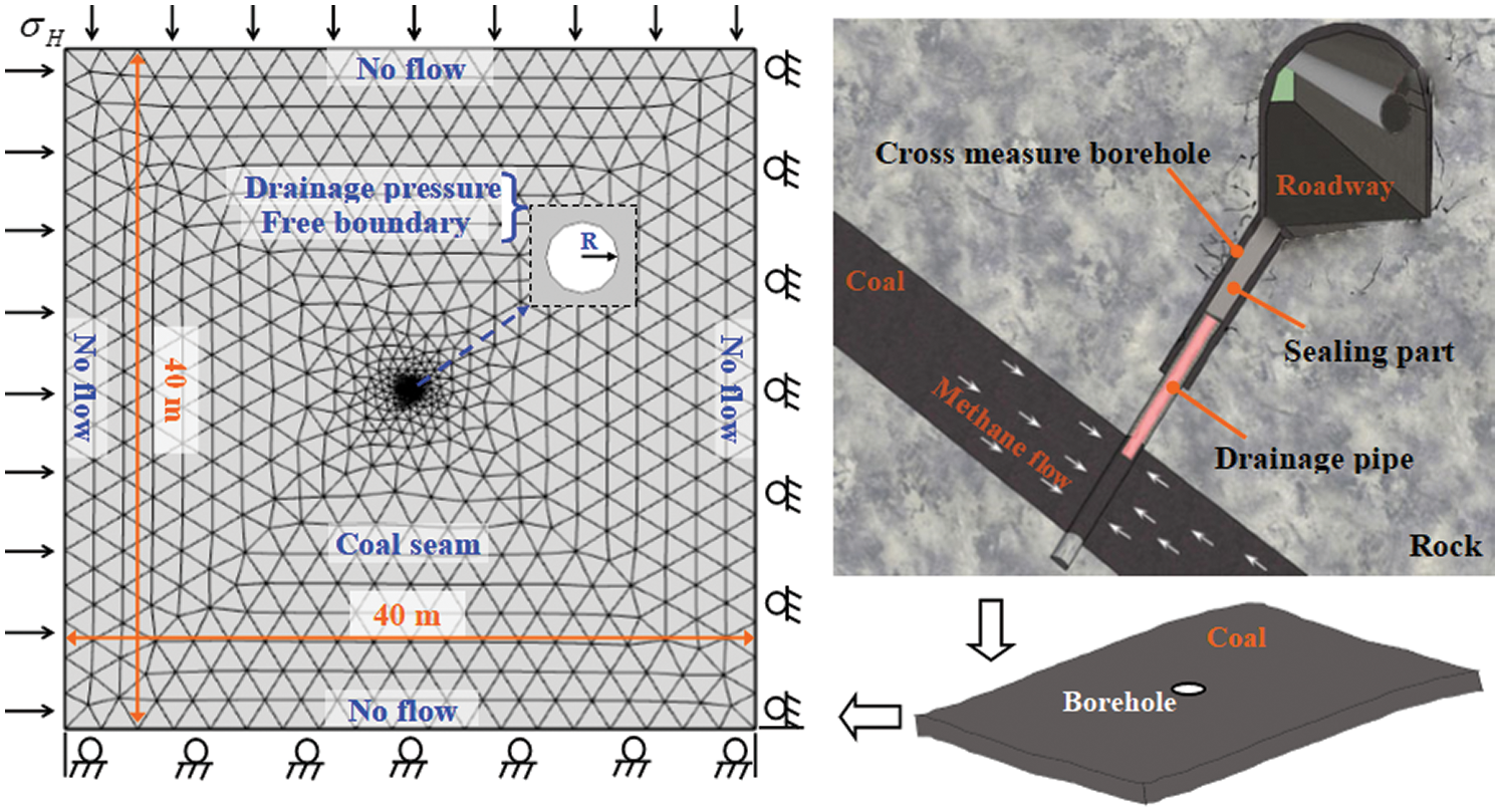
Figure 2: Geometric model and boundary conditions
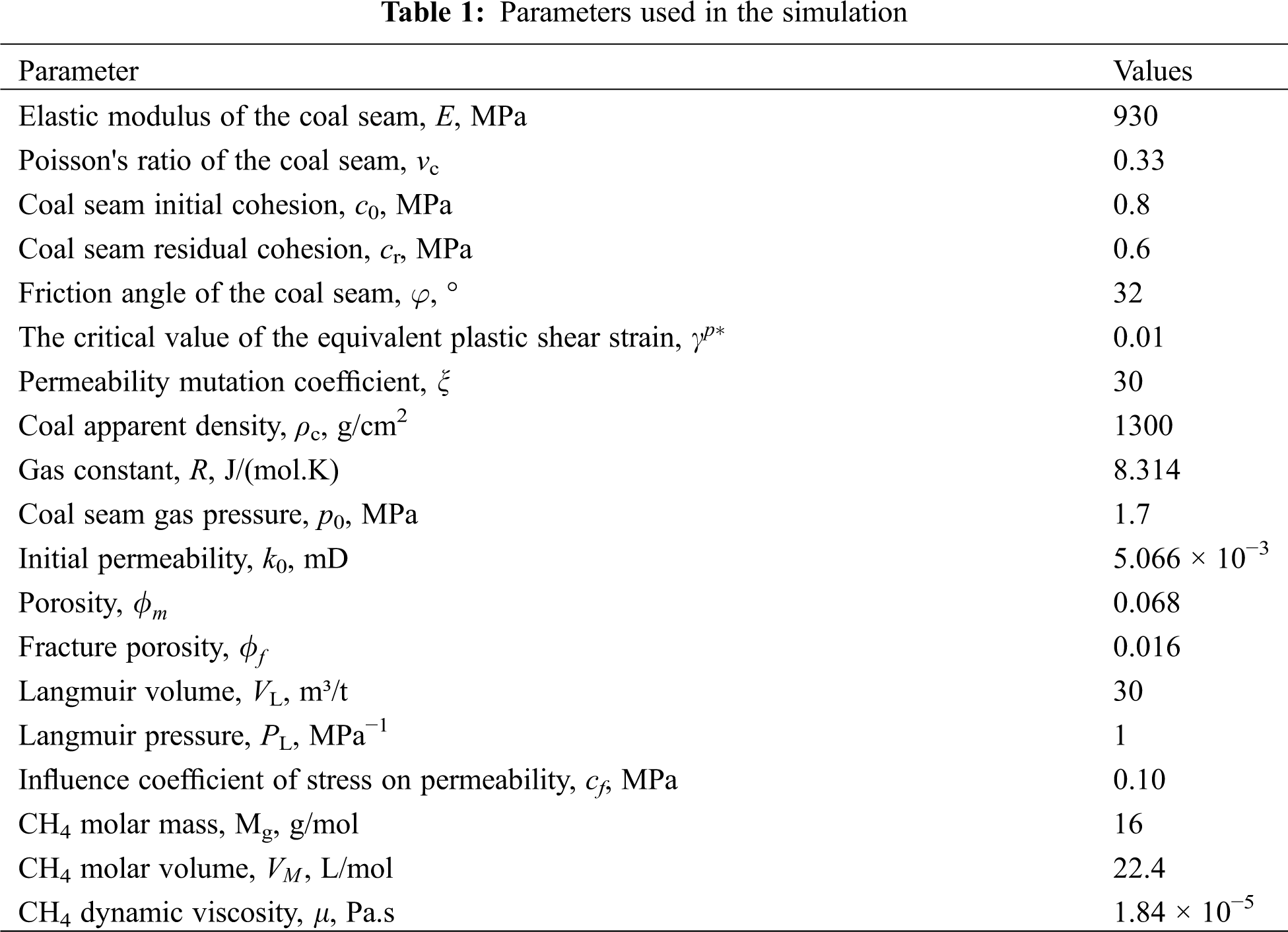
Tab. 1 lists the parameters used in the simulation, all of which were obtained by laboratory tests or field measurements.
3.2 The Influence of the Borehole Radius on Gas Extraction
Taking the borehole radius of 0.1 m as an example, the stress and equivalent plastic strain distribution of the coal body around the borehole are analyzed. After drilling, the radial stress, tangential stress, volume stress and equivalent plastic shear strain of coal seam around the borehole are shown in Fig. 3. It can be seen that the equivalent plastic strain around the borehole is far greater than 0, and the volumetric stress is very small. As the distance from the borehole increases, the equivalent plastic strain decreases sharply, and the volumetric stress increases. When the equivalent plastic strain is greater than 0, the coal is in the plastic softening stage; and when the equivalent plastic strain is greater than the critical value of 0.01, the coal is in the residual stage and failure occurs in the coal. Therefore, the range of the plastic failure zone around the borehole is 0.18 m, the range of the softening zone is 0.062 m, and the thickness of the permeability enhancement zone is 0.142 m, that is, the permeability enhancement radius is 0.242 m. When the distance from the borehole center exceeds 0.242 m, the equivalent plastic strain is 0, the volume stress is the original value, and the coal is in the elastic stage.
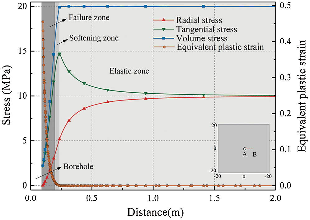
Figure 3: Distribution of stress and plastic strain around a borehole
To investigate the influence of borehole radius on coal permeability, the cases of borehole radius of 0.1~0.4 m were simulated. The permeability evolution characteristics with different borehole radius are shown in Fig. 4a. The maximum permeability is 1250 times the original permeability. With the increase of the borehole radius, the permeability improvement zone gradually increases. Since the permeability improvement zone is approximately a circular area, the radius of the permeability improvement zone is defined as the permeability enhancement radius which increases linearly with borehole radius (Fig. 4b). Moreover, for this coal seam, the permeability enhancement radius is 2.14 times of borehole radius. It can be seen from Fig. 4c, the gas flow rate increases rapidly at the initial time and decreases with time, and the decrease rate is falling. The larger the borehole radius, the larger the gas flow rate. Fig. 4d shows gas pressure distribution in the coal seam after 10 days’ gas extraction. The influenced radius of gas drainage increases with the increase of the borehole radius.
Although the increase of the cavity radius is beneficial to gas drainage, it does not mean that the larger the cavity radius is, the better is in the engineering project. A large cavitation radius will increase the cost of a single borehole, and the cavity radius is limited by the technology and conditions of the coal seam. In this project, the maximum diameter of the mechanical cutter of the drilling machine was 0.5 m, so the borehole radius was determined to be 0.25 m.
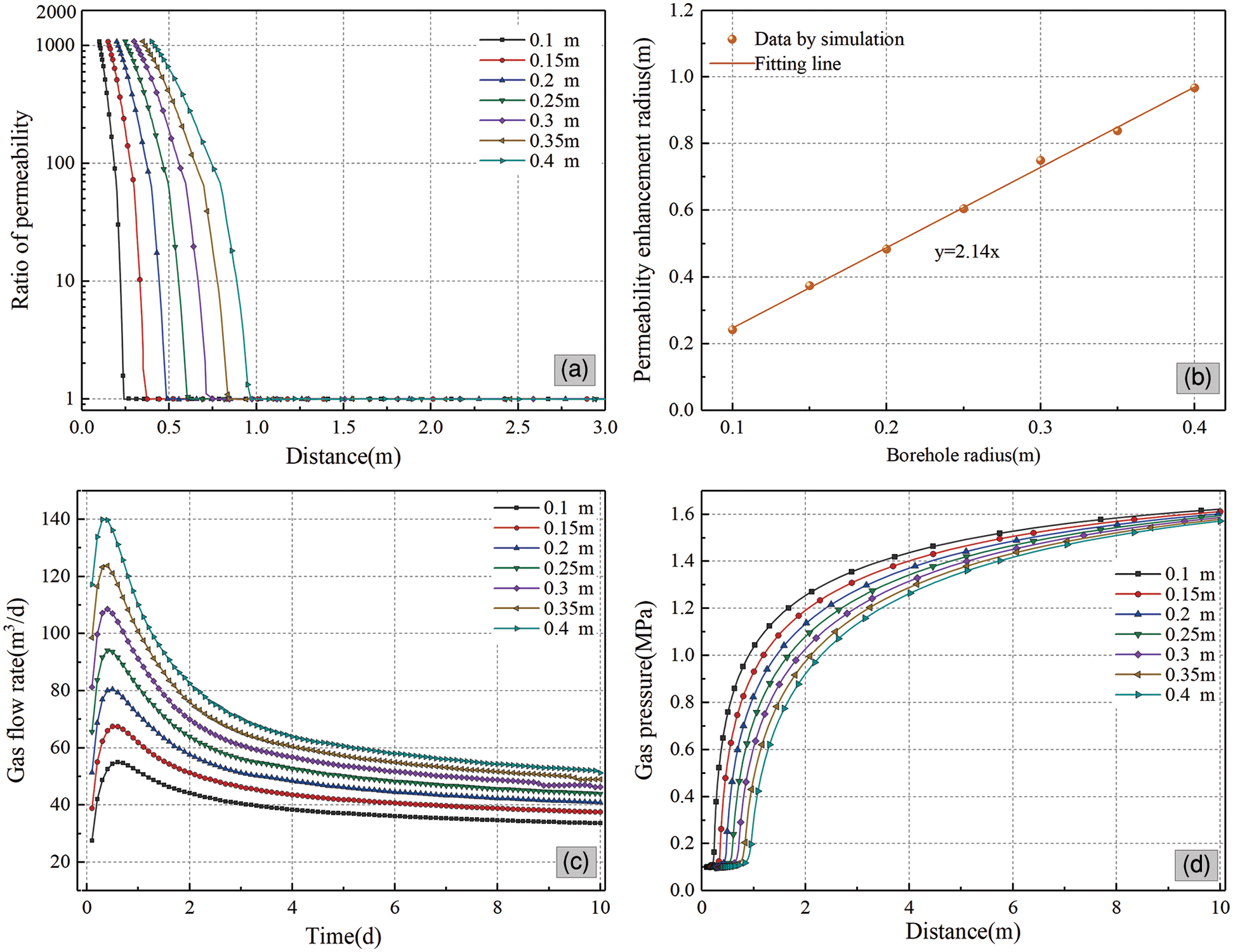
Figure 4: The permeability, permeability improvement radius, gas flow rate, and gas pressure of coal seam with different borehole radius
3.3 The Influence of Borehole Spacing on Gas Extraction
Underground coal seam gas drainage is extremely complicated. There are a large number of drainage holes in an area. Therefore, the spacing between holes is an important factor affecting gas drainage. For the same area, the smaller the borehole spacing is, the more holes are drilled, and the higher the gas extraction efficiency is. However, the increase in the number of boreholes means an increase in costs. Therefore, it is very important to determine a reasonable borehole spacing. When the drilling radius is 0.25 m, the permeability improvement radius of a single drilling hole is greater than 0.604 m. In order to optimize the permeability enhancement effect of the coal seam, the borehole spacing should be 1.028 m. However, due to the influence of mutual interference between the drainage boreholes, the small spacing will reduce the drainage efficiency of each borehole. To determine a reasonable spacing, the gas drainage under eight cases of 3~10 m borehole spacing is simulated.
The colorful diagram of gas pressure in the coal seam after 10 days of extraction at different borehole spacing is shown in Fig. 5a. This figure vividly exhibited the pressure distribution in the coal seam. The influence range increases with the increase of borehole spacing. The gas pressure between four boreholes is the lowest when the borehole spacing is 3 m, which increases with the spacing. The gas pressure distribution of the coal seam along the detection line is shown in Fig. 5b. It can be seen that the larger the borehole spacing, the lower the pressure in the middle of the boreholes. However, there is a reverse away from the borehole. Taking the upper limit of gas pressure of 0.74 MPa that can eliminate outburst risk as to the standard [29], the borehole spacings less than 7 m are all in the requirements.
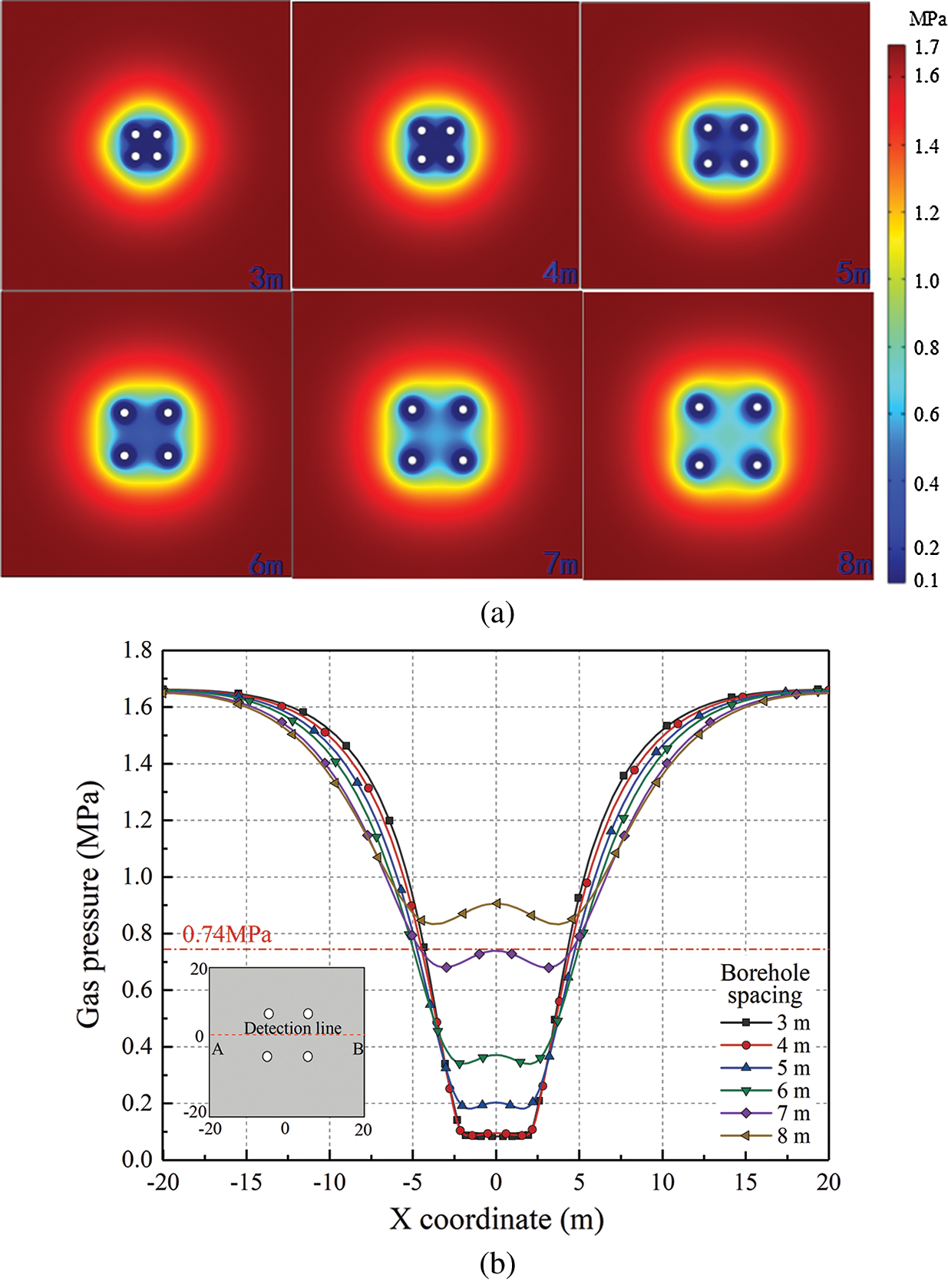
Figure 5: The coal seam gas pressure distribution with different borehole spacing a) Gas pressure distribution in coal seam b) Gas pressure distribution along the detection line
Fig. 6 shows the gas drainage accumulation in 10 days with different borehole spacing. The total amount of accumulated gas increases with the increase of borehole spacing, but the increase rate decreases gradually. The cumulative total amount of gas within 10 days at borehole intervals of 3, 4 and 5 m is 2470.38, 2909.17 and 3,353.54 m3, respectively, which are 17.76% and 15.27% higher than the previous condition. When the spacing between boreholes is 6, 7 and 8 m, the cumulative amount of gas within 10 days is 3686.09, 3911.85 and 4048.15 m3, respectively, increasing by 9.92%, 6.12% and 3.48% compared with the previous cases. It can be seen that when the spacing between boreholes increases from 5 m to 6 m, the cumulative gas extraction quantity increases by less than 10%. If the spacing between boreholes is further increased, the amount of gas extraction will increase slightly, and the extraction effect will be reduced and the extraction time will be increased. Therefore, in order to reduce the influence of mutual interference between boreholes, the reasonable spacing between boreholes is determined to be 6 m.
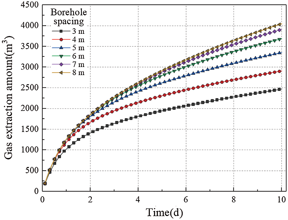
Figure 6: The gas extraction amount with different borehole spacing
The Pingdingshan No. 8 coal mine is located in the southeast of Pingdingshan coalfield. It is a coal mine with coal and gas outburst risk which has happened many times in accidents. The original gas pressure of E9/10 coal seam is 1.7 MPa and the gas content is 10.66 m3/t, both of which are relatively large, so gas extraction must be carried out before mining. However, due to the extremely low permeability of the coal seam, which is only 10−3~10−4 mD, it is difficult to extract gas. Therefore, the borehole enlargement technology is adopted to enhance CBM production.
The cross-seam boreholes are constructed from a high-level gas drainage roadway to the E9/10 coal seam. The control range of boreholes on both sides of the air roadway is 14 and 18 m, respectively. Seven boreholes are arranged in two rows for each group, and the spacing between boreholes is 6 m. Boreholes 1#, 3#, 5#, 7# are placed in odd rows and borehole 2#, 4#, 6# are placed in even rows. The borehole layout is shown in Fig. 7. The process of hole construction is as follows: Firstly, drill a hole from the high-level gas drainage roadway to the coal seam. The diameter of the drilling bit is 133 mm. When the borehole drilling into the coal seam, inject high-pressure water into the drill bit, and at the same time, the cutting blade in the drilling bit will be opened, which will cut the coal seam. The enlarged borehole is formed by mechanical cutting and hydraulic flushing, and the coal dust can be flushed out by water.
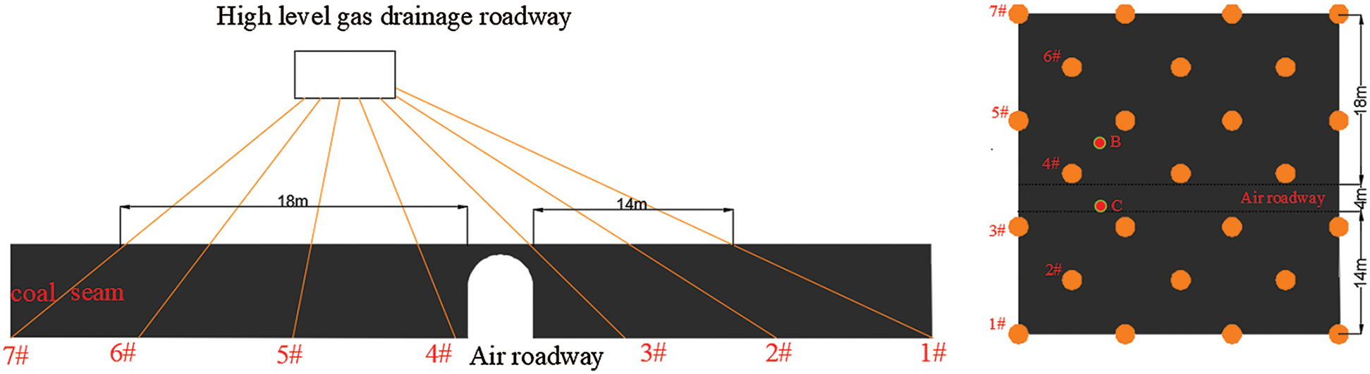
Figure 7: The layout of the boreholes
In the construction process of hydraulic cavitation, the cavitation time, water pressure and coal slag quantity were recorded. The water pressure used in the cave construction was about 16 MPa, and the construction time of a single hole was 20~60 min. The coal slag quantity of six groups of boreholes was counted, as shown in Fig. 8. It is difficult to remove coal debris from the downward borehole [30]. According to previous engineering experience, it can meet the requirement of gas extraction when the slag discharge rate more than 70%. Considering the cave radius of 0.25 m, the theoretical coal quantity from the cave is 0.257 t/m. The actual average coal slag discharge is around 0.2 t/m, which is 77.82% of the theoretical value. This indicates that the cavitation process is successful and the effect is obvious.
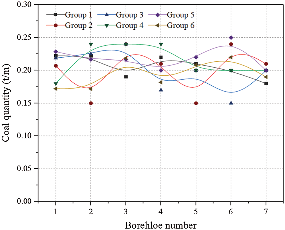
Figure 8: Slag discharge per meter of drilling boreholes
In order to verify the permeability increasing effect of enlarged boreholes, the natural gas flow rate from normal boreholes and enlarged boreholes was monitored. Two normal boreholes B and C with a diameter of 133 mm were constructed near the 4# borehole which has not been constructed. After drilling was completed, the hole was sealed immediately and the natural gas flow rate flow was measured. Then the 4# enlarged borehole was constructed, and the hole was sealed immediately after cavitation and the natural gas flow was measured. The natural gas flow of normal boreholes B and C and enlarged borehole 4# were shown in Fig. 9. The maximum gas flow rate in 4# enlarged borehole is 0.059 m3/min, while the maximum gas flow rate in the normal holes was 0.026 and 0.08 m3/min, respectively. The natural gas flow rate of the three boreholes decreased with time, and at the same time, the decreasing rate gradually slowed down. Although the flow rate of the enlarged borehole was decreasing more than that of the normal borehole, the gas flow rate of the enlarged borehole was much higher than that of the normal boreholes all the time. The natural gas flow rate from the enlarged borehole was 2.3–7.3 times as much as that of the normal holes, and the natural gas flow of the enlarged borehole lasted longer than that of the normal borehole.
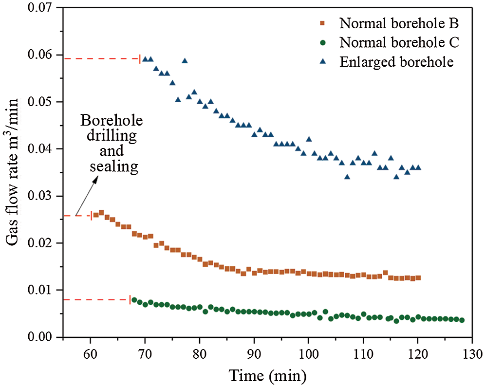
Figure 9: The comparison of the natural gas flow rate
To obtain the influence zone of the enlarged borehole on enhanced gas drainage, the gas flow rate of 4# enlarged borehole was continuously recorded before, during, and after the construction of 5# borehole. The results are shown in Fig. 10. The gas flow of 4# borehole before 5# construction is about 0.034 m3/min. When 5# borehole was being drilled, the gas flow rate of 4# borehole was disturbed and fluctuated, and then decreased to about 0.03 m3/min. After the construction of 5#, the gas flow rate decreased to about 0.027 m3/min. Considering that the actual borehole spacing was 6.08 m between 4# and 5# boreholes, the influence range of the enlarged borehole was larger than 6 m, which demonstrates that the borehole spacing of 6 m was arranged reasonably.
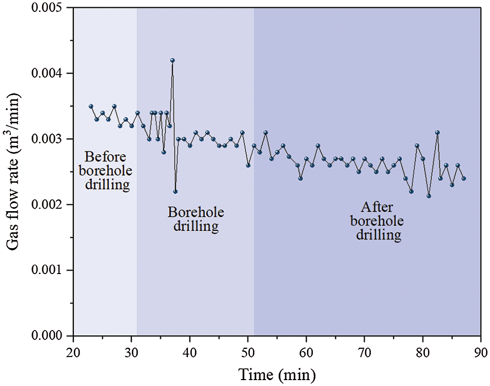
Figure 10: Natural gas flow rate of 4# borehole during 5# borehole construction
After the completion of the drilling, boreholes were incorporated into the main extraction pipeline for gas drainage. The gas extraction concentration and gas amount of a group of boreholes were monitored in 20 days, as is shown in Fig. 11. The average gas extraction concentration can reach about 42%, and the average gas extraction amount reaches 0.53 m3/min, which are both much more than the previous gas drainage data. The high concentration gas is beneficial to be used as energy. After two months of extraction, the gas pressure of the coal seam is reduced to below 0.74 MPa and the gas content is reduced to below 6 m3/t (the critical values for coal mining in Chinese coalmine [29]). This technique eliminates the outburst risk in this area and ensures safety in coal production.
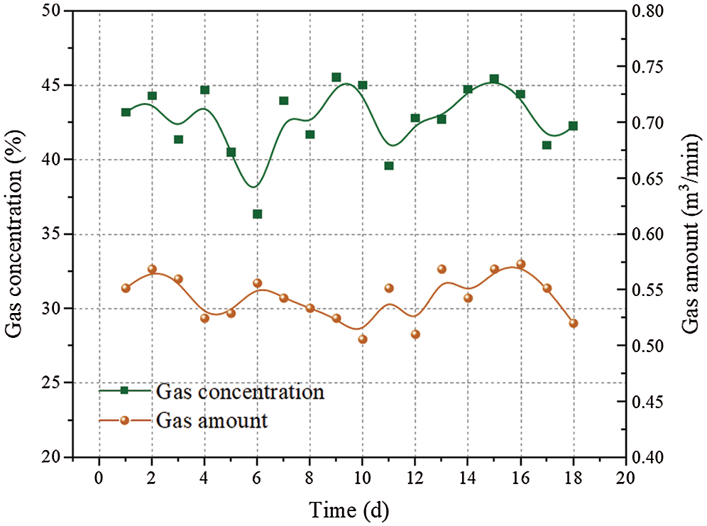
Figure 11: Gas extraction amount and concentration of a group of boreholes
In this paper, the permeability evolution equations of the coal seam around an enlarged borehole were established based on the strain-softening model, and the gas migration equations were established based on the dual-medium model. The reasonable borehole parameters of E9/10 coal seam in Pingdingshan No. 8 coal mine were determined by numerical simulation, and then field application was carried out. The main conclusions are as follows:
(1) The COMSOL Multiphysics finite element software was used to simulate the enlarged borehole enhanced-gas drainage of the 21070 working face in E9/10 coal seam from the high-level gas drainage roadway. The reasonable borehole radius is 0.25 m and borehole spacing is 6 m.
(2) The average coal quantity flushed from the borehole obtained from field statistics is about 0.2 t/m, which accounts for 77.82% of the theoretical value. This illustrates that the hydraulic and mechanical method can meet the purpose of borehole enlargement.
(3) The natural gas flow rate from an enlarged borehole is 2.3–7.3 times as much as that of the normal boreholes, and the gas flow lasts longer from enlarged holes. The field investigation showed that the influence range of an enlarged borehole was greater than 6 m, which means the borehole spacing designed was reasonable.
(4) By monitoring the gas extraction data of a group of boreholes, the average gas extraction concentration reaches about 42%, and the average gas extraction amount can reach 0.53 m3/min, which is beneficial for energy utilization. After two months of gas extraction, the gas pressure of the coal seam was reduced to below 0.74 MPa, and the gas content was reduced to below 6 m3/t, which eliminated the outburst risk in this area and provided a guarantee for safe coal mining.
Funding Statement: This work was supported by the Assistance Program for Future Outstanding Talents of China University of Mining and Technology (No. 2020WLJCRCZL041) and the Postgraduate Research & Practice Innovation Program of Jiangsu Province (No. SJCX20_0816).
Conflicts of Interest: The authors declare that they have no conflicts of interest to report regarding the present study.
1. Karacan, C. O., Okandan, E. (2001). Adsorption and gas transport in coal microstructure: Investigation and evaluation by quantitative x-ray CT imaging. Fuel, 80(4), 509–520. DOI 10.1016/S0016-2361(00)00112-5. [Google Scholar] [CrossRef]
2. Aguado, M. B. D., Nicieza, C. G. (2007). Control and prevention of gas outbursts in coal mines, Riosa-Olloniego coalfield. Spain International Journal of Coal Geology, 69(4), 253–266. DOI 10.1016/j.coal.2006.05.004. [Google Scholar] [CrossRef]
3. Skoczylas, N., Dutka, B., Sobczyk, J. (2014). Mechanical and gaseous properties of coal briquettes in terms of outburst risk. Fuel, 134(4), 45–52. DOI 10.1016/j.fuel.2014.05.037. [Google Scholar] [CrossRef]
4. Cao, Y., He, D., Glick David, C. (2001). Coal and gas outbursts in footwalls of reverse faults. International Journal of Coal Geology, 48(1), 47–63. [Google Scholar]
5. Karacan, C. Ö., Ruiz, F. A., Cotè, M., Phipps, S. (2011). Coal mine methane: A review of capture and utilization practices with benefits to mining safety and to greenhouse gas reduction. International Journal of Coal Geology, 86(2), 121–156. DOI 10.1016/j.coal.2011.02.009. [Google Scholar] [CrossRef]
6. Yin, W., Fu, G., Yang, C., Jiang, Z., Zhu, K. et al. (2017). Fatal gas explosion accidents on Chinese coal mines and the characteristics of unsafe behaviors: 2000–2014. Safety Science, 92, 173–179. DOI 10.1016/j.ssci.2016.09.018. [Google Scholar] [CrossRef]
7. Dong, J., Cheng, Y., Jin, K., Zhang, H., Liu, Q. et al. (2017). Effects of diffusion and suction negative pressure on coalbed methane extraction and a new measure to increase the methane utilization rate. Fuel, 197, 70–81. DOI 10.1016/j.fuel.2017.02.006. [Google Scholar] [CrossRef]
8. Palmer, I. (2009). Permeability changes in coal: Analytical modeling. International Journal of Coal Geology, 77(1–2), 119–126. DOI 10.1016/j.coal.2008.09.006. [Google Scholar] [CrossRef]
9. Pan, Z., Connell, L. D. (2012). Modelling permeability for coal reservoirs: A review of analytical models and testing data. International Journal of Coal Geology, 92(2), 1–44. DOI 10.1016/j.coal.2011.12.009. [Google Scholar] [CrossRef]
10. Lu, Y., Liu, Y., Li, X., Kang, Y. (2010). A new method of drilling long boreholes in low permeability coal by improving its permeability. International Journal of Coal Geology, 84(2), 94–102. DOI 10.1016/j.coal.2010.08.009. [Google Scholar] [CrossRef]
11. Wang, L., Lu, Z., Chen, D., Liu, Q., Chu, P. et al. (2020). Safe strategy for coal and gas outburst prevention in deep-and-thick coal seams using a soft rock protective layer mining. Safety Science, 129, 104800. DOI 10.1016/j.ssci.2020.104800. [Google Scholar] [CrossRef]
12. Wang, S., Elsworth, D., Liu, J. (2013). Permeability evolution during progressive deformation of intact coal and implications for instability in underground coal seams. International Journal of Rock Mechanics & Mining Sciences, 58(1), 34–45. DOI 10.1016/j.ijrmms.2012.09.005. [Google Scholar] [CrossRef]
13. Yin, G., Jiang, C. B., Wang, J. G., Jiang, X. (2013). Combined effect of stress, pore pressure and temperature on methane permeability in anthracite coal: An experimental study. Transport in Porous Media, 100(1), 1–16. DOI 10.1007/s11242-013-0202-6. [Google Scholar] [CrossRef]
14. Liu, Z., Li, Z. H., Yang, Y., Tang, Y. (2012). Study of outburst prevention technology by comprehensive hydraulic drilling downward through coal-seam. Journal of Mining & Safety Engineering, 29(4), 564–569. http://ckxb.cumt.edu.cn/EN/Y2012/V29/I4/564. [Google Scholar]
15. Liu, M., Cui, K., Liu, Y., Deng, Q., Liu, Y. (2012). Analysis on outburst prevention mechanism of borehole hydraulic flushing measures for deep and low permeability seam. Coal Science & Technology, 40(2), 45–48. DOI 10.13199/j.cst.2012.02.50.liumj.019. [Google Scholar] [CrossRef]
16. Zhou, H., Cheng, Y., Liu, H., Guo, P., Wang, L. (2011). Permeability improvement technology of array crossing boreholes and its application in outburst coal seam. Journal of China Coal Society, 36(9), 1515–1518. DOI 10.1007/s12583-011-0163-z. [Google Scholar] [CrossRef]
17. Hoek, E., Wood, D., Shah, S. (1992). In a modified Hoek–Brown failure criterion for jointed rock masses. International ISRM Symposium on Rock Characterization. Chester, UK, Chester, UK: Thomas Telford Publishing. [Google Scholar]
18. González-Cao, J., Varas, F., Bastante, F. G., Alejano, L. R. (2013). Ground reaction curves for circular excavations in non-homogeneous,axisymmetric strain-softening rock masses. Journal of Rock Mechanics and Geotechnical Engineering, 5(6), 431–442. DOI 10.1016/j.jrmge.2013.08.001. [Google Scholar] [CrossRef]
19. Alonso, E., Alejano, L. R., Varas, F., Fdez-Manin, G., Carranza-Torres, C. (2003). Ground response curves for rock masses exhibiting strain-softening behaviour. International Journal for Numerical and Analytical Methods in Geomechanics, 27(13), 1153–1185. DOI 10.1002/nag.315. [Google Scholar] [CrossRef]
20. Hajiabdolmajid, V., Kaiser, P. (2003). Brittleness of rock and stability assessment in hard rock tunneling. Tunnelling & Underground Space Technology Incorporating Trenchless Technology Research, 18(1), 35–48. DOI 10.1016/S0886-7798(02)00100-1. [Google Scholar] [CrossRef]
21. Labuz, J. F., Zang, A. (2012). Mohr–Coulomb failure criterion. Rock Mechanics & Rock Engineering, 45(6), 975–979. DOI 10.1007/s00603-012-0281-7. [Google Scholar] [CrossRef]
22. Somerton, W. H., Söylemezoǧlu, I. M., Dudley, R. C. (1975). Effect of stress on permeability of coal. International Journal of Rock Mechanics & Mining Sciences & Geomechanics Abstracts, 12(5–6), 129–145. DOI 10.1016/0148-9062(75)91244-9. [Google Scholar] [CrossRef]
23. Wang, J. A., Park, H. D. (2002). Fluid permeability of sedimentary rocks in a complete stress–strain process. Engineering Geology, 63(3), 291–300. DOI 10.1016/S0013-7952(01)00088-6. [Google Scholar] [CrossRef]
24. An, F., Cheng, Y., Wang, L., Li, W. (2013). A numerical model for outburst including the effect of adsorbed gas on coal deformation and mechanical properties. Computers & Geotechnics, 54(10), 222–231. DOI 10.1016/j.compgeo.2013.07.013. [Google Scholar] [CrossRef]
25. Perera, M. S. A., Ranjith, P. G., Choi, S. K., Bouazza, A. (2013). A parametric study of coal mass and cap rock behaviour and carbon dioxide flow during and after carbon dioxide injection. Fuel, 106(2), 129–138. DOI 10.1016/j.fuel.2012.10.056. [Google Scholar] [CrossRef]
26. Liu, Q., Cheng, Y., Zhou, H., Guo, P., An, F. et al. (2014). A mathematical model of coupled gas flow and coal deformation with gas diffusion and klinkenberg effects. Rock Mechanics and Rock Engineering, 48(3), 1163–1180. DOI 10.1007/s00603-014-0594-9. [Google Scholar] [CrossRef]
27. Warren, J. E., Root, P. J. (1963). The behavior of naturally fractured reservoirs. Society of Petroleum Engineers Journal, 3(3), 245–255. DOI 10.2118/426-PA. [Google Scholar] [CrossRef]
28. Liu, Z., Cheng, Y., Jiang, J., Li, W., Jin, K. (2017). Interactions between coal seam gas drainage boreholes and the impact of such on borehole patterns. Journal of Natural Gas Science and Engineering, 38, 597–607. DOI 10.1016/j.jngse.2017.01.015. [Google Scholar] [CrossRef]
29. National Coal Mine Safety Administration Office (2019). Regulations on coal and gas outburst prevention. Beijing: Emergency Management Press. [Google Scholar]
30. Hu, G., Cai, F. (2016). gas drainage technique by downward through bed hole of y-shape ventilation gob-side entry retaining. Safety in Coal Mines, 47(2), 77–80. DOI 10.13347/j.cnki.mkaq.2016.02.021. [Google Scholar] [CrossRef]
 | This work is licensed under a Creative Commons Attribution 4.0 International License, which permits unrestricted use, distribution, and reproduction in any medium, provided the original work is properly cited. |