| Energy Engineering |
DOI: 10.32604/EE.2022.016034
REVIEW
A Review of Research Status and Scientific Problems of Floating Offshore Wind Turbines
1China State Shipbuilding Co., Ltd., Beijing, 100097, China
2Institute of Engineering Thermophysics, Chinese Academy of Science, Beijing, 100190, China
3CSIC Haizhuang Windpower Co., Ltd., Chongqing, 401122, China
*Corresponding Author: Xinbao Wang. Email: wangxinbao20@mails.ucas.ac.cn
Received: 02 February 2021; Accepted: 24 June 2021
Abstract: With the continuous utilization of offshore wind resources, the installation depth and capacity of offshore wind turbines are increasing. In order to meet construction requirements of renewable energy, offshore wind farms are bound to develop further and deeper into the sea. As a result, a novel kind of power generation equipment, Floating Offshore Wind Turbines (FOWT), emerges as the times require. Consequently, this paper provides an objective comment on some key scientific difficulties. Firstly, The statistics and forecast of the market demand and installed capacity of offshore wind energy show a steady growth. After that, the advantages of constructing FOWT and most floating projects in various countries are summarized. And then, the reconstruction design of blades is reviewed under “Reynolds number” and “Froude number” similarity criterion, which is a prerequisite for achieving specific aerodynamic performance. So far, this paper focuses on aerodynamic researches, including aerodynamic forces and flow fields. On this basis, pitch angle control strategies are proposed to reduce aerodynamic forces on the premise of ensuring power generations. Finally, some other joint science problems to be solved are listed. Whether theoretical analysis, numerical simulations, ocean engineering basin tests, wind tunnel experiments or prototype sea measurements, FOWT is expected to break through various obstacles and finally achieve efficient and stable commercial operations.
Keywords: FOWT; scale effect; motion response; load control
Wind energy has been collected and utilized for a long time because it can be regenerated easily and does not cause any environmental pollution. From navigations and irrigations to electric power generations, humans are pursuing more efficient and feasible usage. With the promotion of technological innovation and progress, wind power technology compared with traditional fossil and nuclear energy shows a green form and greater potentials in reducing the cost. Its proportion in the power supply in the past decade has been steadily increasing, and its rapid growth has also promoted the transformation of energy and business model in some regions [1]. Until the end of 2020, the global total installed capacity reached 743 GW, and the annual installed capacity was 93 GW, an increase of 53% over 2019, but this growth is not sufficient to ensure the world achieves net zero carbon dioxide growth by 2050, and the world needs to be installing wind power three times faster over the next decade in order to stay on a net zero carbon dioxide growth pathway and avoid the worst impacts of climate change [2]. As mentioned above, onshore wind power technology is gradually maturing.
The rapid construction of wind turbines will inevitably lead to the rise of offshore wind power. Wind farms onshore cause electromagnetic disturbances and noise pollutions to the human life nearby. At the same time, wind turbines with a continuous mega-size and higher energy conversion efficiency are more suitable for the offshore environment and can obtain more annual utilization hours [3]. According to the data provided by the International Energy Agency (IEA), it was predicted that by 2023, the world’s new offshore installed capacity would reach 52–60 GW, with half of the increase coming from Europe and the rest from other regions [4]. The Global Wind Energy Council (GWEC) also forecasted that through 2030, more than 205 GW of new offshore wind capacity would be added globally, including at least 6.2 GW of floating offshore wind [5]. The European Wind Energy Association (EWEA) also predicted that the fastest growing area of the floating wind power in the next two to five years would be the United States, and the deep-sea area on the north east coast was currently under development, which would be a very large market. Asia was also an important offshore market, Japan and South Korea with limited land areas and vast sea areas would be a main growth markets, followed by coastal countries such as China. However, due to the relatively flat and shallow sea area of China, constructions of projects might be limited [6]. Fig. 1 describes the annual and cumulative installations (including forecast results) of offshore wind turbines worldwide since 2007. From the figure, it can be seen a stable growth trend of offshore wind turbines. Under the current policy and expected bidding regime, the offshore market is expected to double in the future [5].
Figure 1: Global annual and cumulative installed capacity yearly (Fig. 1 was reproduced based on the data reported by the Global wind energy council)
However, with an increase of offshore installed capacity and limited shallow sea resources, the offshore wind power in many island countries cannot meet the needs of long-term power plannings. Wind farms are bound to develop into far-reaching areas. It is generally considered that an installation with a water depth greater than 50 m or an offshore distance greater than 50 km is a deep-sea wind farm. On this basis, the installation cost of offshore wind turbines with pile foundations, jacket foundations or gravity foundations is too high to assemble, and hydrodynamic loads caused by wave and currents are significantly increased. Therefore, this form will no longer be applicable, but a floating offshore wind turbine installed on a floating platform and fixed by a mooring system pulling by catenaries or tension tendons. This new concept involves the technology of offshore oil and gas extraction industry and the knowledge of marine engineering fields. After simulations, experiments and prototype demonstrations, it is hopefully expected to achieve stable commercial operations.
This paper starts with giving the advantages of developing FOWT in deep sea areas, as well as properties and installation methods of different floating platforms. Then, with the birth of the first floating project “Hywind”, a series of floating farms under development and completed are listed. So far, this paper focuses on aerodynamic researches, including aerodynamic forces and flow fields. Before that, the reconstruction design of blades under the similarity criterion of “Reynolds number” and “Froude number” is reviewed, because this process is a prerequisite for obtaining aerodynamic performance. In the last section, some other key scientific problems to be solved are simply stated. In general, this paper focuses on describing research history of FOWT in aerodynamics. People in this field can have a more comprehensive understanding and certain guiding significance by referring this article.
As a novel concept, the rapid development of the floating wind power technology is not only dependent on the progress of scientific research abilities, but also restricted by other factors such as national policies, for example, The goal of carbon neutrality has greatly promoted the rise of renewable energy, especially the wind energy. From a global perspective, the FOWT continues to be in the test and verification periods. Most of the floating projects in various countries are under constructions, and there are still some obstacles to break. In addition, the deeper installation area and the speed of the cost reduction will be the immediate criterions to limit the development of FOWT, but its unprecedented unique advantages will still cause a wide range of research frenzy. Here is the list of its strengths, floating platforms and projects, to show that it is the inevitable process of the wind power technology.
Compared with turbines with fixed foundations, FOWT has been paid more attentions for its outstanding advantages, which are embodied in the following aspects.
Wind energy resources are abundant and wind quality is better. Being away from a coast can effectively get rid of the interference of terrains, buildings and other obstacles. When making a micro site selection, there is no need to consider the restrictions of obstacles on the layout of the turbines. In this area, the wind speed is large and stable [7], the turbulence intensity is small, and the average wind power density is high. Once the wind farm is established, the interference of land wind and the surface roughness can be ignored to a certain extent. Theoretically, it can form a more stable flow field, obtain a more stable power output, and reduce load fluctuations and fatigue stresses, thus reducing the cost of operations and maintenances. However, higher atmospheric stability and smaller wind shear index make the wake recover slower, which will seriously affect the fatigue load and power output performance of downstream wind turbines. Some scholars have studied the wake characteristics of floating wind turbines, which shows that the power reduction of downstream wind turbine can reach nearly 30%.
There is less damage to the ecological environment. While making full use of abundant deep sea wind resources, FOWT does not occupy onshore and human activity areas, reduces the impact on the coastal industrial production and residents’ life, and does not occupy shorelines and ship channels; due to the remoteness, noise, electromagnetic interference, etc. need not be considered. In addition, compared with offshore fixed foundations, the floating foundation does not need a pile driving into the seabed, which eliminates the damage on ocean creatures’ and their living habits. However, operations of floating wind turbines need the support of effective remote monitoring and control methods. In order to reduce the number of maintenance personnel going to sea, it is necessary to improve the stability and self-healing abilities of wind turbines. A complete set of adaptive intelligent control strategy needs to be proposed.
The wind power is more efficient and the operation is more stable. Continuous giant and heavy wind turbines make blades longer and the sweep area wider, which causes the capacity is larger and more power generations. Therefore, the utilization efficiency of wind is significantly improved. Besides, the floating foundation avoids the constraints of different seabed conditions and can be towed and reused in the extreme storm weather conditions to prevent damages, so its environmental adaptability has greatly improved. Generally speaking, the vast area of the deep sea makes it possible to build large-scale floating wind farms with more installed capacities and larger single capacity than onshore and offshore fixed wind turbines.
Floating platforms play a key role in keeping the turbine floating on water, which is a foundation of this equipment. A FOWT system consists of wind turbine, tower, floating platform and mooring system. The floating platform involves the Spar Platform (Spar), the Semi-Submersible Platform (semi-Sub) and the Tension Leg Platform (TLP) [8], and some people also proposed barge platforms and combination platforms. The descriptions of various platforms are shown in Fig. 2.
Through ballast tanks, the Spar platform makes the center of gravity lower than the floating center to keep stable in water. Then some catenaries arranged radially ensure the overall position of the platform. Generally, there are three catenary lines with an equal angle of 120°, and the bottom is fixed on the seabed by anchor chains or suction buckets. The platform is deeper below water surface, and heave motions are smaller than that of Semi-Sub platforms. However, due to a low contribution of spar foundation waterline to the stability, its roll and pitch values are larger. The installation depth can reach 3000 m, which is suitable for deeper sea conditions, and has reached commercial operations at present.
The Semi-Sub platform is based on a floating tank located on the sea surface to keep stability. A floating tank is large in plane size but small in height, so as to provide enough buoyancy and ensure the resistance against overturning [9]. In general, the platform is pulled by six radial distribution catenaries and fixed on the seabed. The shallow draught greatly saves installation cost. However, large rolling and pitching motions will affect the generation efficiency and turbine’s life. Secondly, it is difficult to develop and design dynamic cables. What’s more, catenaries occupy a large area of sea, and ships traveling near the wind farm will have the risk of colliding with the anchor chains.
As for the TLP platform, from top to bottom, there are central column, floating box with a triangular or rectangular section, tension tendons in a tension state and seabed fixtures such as piles, suction buckets or gravity equipment. The gravity of this foundation is less than the buoyancy, and the discrepancy is compensated by a tension of tension tendons. These characteristics make this form have good performance of heave and sway motions. However, a disadvantage is that the natural motion frequency of horizontal degrees of freedom is closer to the wave frequency, and frequencies coupling of superstructure and mooring system are also prone to resonance motions, so it is difficult to avoid resonances in design. Besides, the tension tendons are obviously affected by currents, and their installation and connection devices cannot directly use the design experience of tension leg oil platforms. This form is currently in a state of verifications and improvements.
Figure 2: A description of four floating platforms. Available from: Wind Europe. Floating offshore wind vision statement
In the design of the floating platform, it is necessary to meet the strict requirements for static stability and seakeeping. Concurrently, compared with fixed wind turbinea, the structural safety of floating systems is more prominent. Manufacturers need to improve the characteristics of platforms on the basis of fixed ones. The cost can be significantly reduced by optimizing designs and reducing requirements for the motion performance.
Installation methods of various foundations are also different because of their own characteristics, so as to keep economy and safety.
The Semi-Sub foundation and upper wind turbine can be combined onshore, then towed to a destination by a tugboat. In the construction process, expensive large crane and lifting vessels can be avoided, and the controllable period can be greatly increased, so as to significantly reduce the construction cost of the whole wind farm.
The Spar platform foundation can be manufactured onshore, and then towed to the predetermined sea area. It is automatically righted by pressurizing a bottom ballast tank, and then a wind turbine is hoisted in place by a hoisting ship. But at the same time, the offshore hoisting operation is increased, which has higher cost and risk. The construction time is long and the cost is high, but the stability is better.
However, the wind turbine based on TLP can be installed and debugged onshore, so as to avoid various problems of offshore installation and debugging. Before the installation of the turbine, it is necessary to connect tension legs with the foundation on site. This puts forward higher requirements for large-scale equipment, diving operation, connection structure design, etc. The economy is poor, the installation accuracy control is difficult, the construction risk is high, but the stability is better.
From the above concepts of floating platforms, cost, benefits and the future of floating projects are concerned by the whole world. Europe is in a leading state of commercial operation. The Spar and Semi-Sub systems have already been applied to an actual grid-connected power generations, while the TLP system is still being tested and verified [6]. Japan’s nuclear leakage accident is intended to show that wind energy is more suitable, and because of limitations of its onshore resources, it will be committed to a development of offshore wind turbines. Besides, the deep sea area of Japan promotes a prosperity of FOWT. In China, where offshore wind power started late, FOWT is still in the numerical simulations and experimental verifications processes, but there are also relevant institutions and universities devoted to researches, and have made some breakthroughs in motion responses and load analysis under complex environmental conditions. Table 1 shows floating offshore wind projects around the world.

3 Research Status of Aerodynamics
When it comes to wind turbines, aerodynamic is always enduring for practitioners and researchers. From the aerodynamic study pattern, it mainly includes numerical simulations, wave pool tests and wind tunnel experiments.
In terms of numerical simulations, commonly used aerodynamic analysis codes include: FAST, SIMO, HAWC2, DeepC, Bladed, BA-simula, etc. These codes mostly apply the Blade Element Momentum (BEM) theory of Glauent’s correction and tilted wake correction of empirical data and they are generally designed for fixed-foundation wind turbines. However, for FOWT, the floating platform, the hydrodynamic model and mooring system are added in addition to aerodynamic and structural modules, which makes the software used above codes not universal. At the same time, the complex motion responses will make it in a wake generated by itself, and they are mostly simulated under specific conditions, which can not achieve strong coupling input of wind-wave-current parameters and the comprehensive analysis of multi-physical fields [10]. In this regard, some organizations have begun to invent their own general analysis software suitable for the numerical simulations in multiple fields. Most researchers prefer FAST (Fatigue, Aerodynamics, Structures and Turbulence) and CFD (Computational Fluid Dynamics) analysis currently. Among them, CFD technology has become mature, which can model the whole structures of a wind turbine, calculate loads and analyze aerodynamic performances preeminently. FAST, which is developed by NREL (National Renewable Energy Laboratory), integrates a series of software and modules. In the process of simulations, Turbsim and IEWind are used to import wind files, structural parameters and airfoil data are input by BMODES and Foilchek, and Aerodyn calculates the aerodynamic performance. Similarly, hydrodynamic and mooring systems have their own parts to deal with. It can simulate and analyze dynamic models, including wind inflow, aerodynamics, elasticity and control of wind turbines, as well as incident wave, current, hydrodynamics, platform and mooring dynamics of floaters [11]. Then the open FAST code source is available for modification and migration, which makes it more flexible and adaptable. All in all, no matter what kind of simulation tool is operated, calculation results need to be compared with test data or analysis results of other simulation software to verify the mechanism of load distributions. Furthermore, a correctness of the model is explained, and new control strategies are needed.
In model tests, floating wind turbines are generally carried out in ocean engineering pools with scale model, such as Marintec ocean engineering pool, university of California Berkeley model pool, MARIN ocean engineering pool, OCEANIDE ocean engineering pool, Hamburg model boat pool, etc. Besides, a wave-making plate can generate regular waves or irregular waves such as random waves with unidirectional or other modes of propagation. Wave eliminators are set at the edge of the basin to reduce the interference to wave diffusions. And a current making pump can provide uniform or laminar currents with different speeds and directions. Thus, the wave and current conditions in the hydrodynamic tests and mooring tests can be satisfied. Compared with prototype tests, model tests have the advantages of low cost and convenient construction, which significantly reduces uncertainty factors. However, before hydrodynamic and aerodynamic tests, it is necessary to establish different similarity criteria and determine an effective scale ratio of the significant experimental results [12]. This situation leads to the similarity criteria can not be unified when multiple conditions are applied at the same time. And, Froude criterion has been widely used in structural hydrodynamic similarity, and Reynolds similarity is related to the scale effect in the experiment of obtaining aerodynamic forces. So many corrections are applied, such as adjusting the input of environmental parameters, modifying the rotor, redesigning blades, etc. However, there is always a deviation between experimental aerodynamic forces and the simulation results.
As for wind tunnel equipment, fan arrays with matrix arrangement can generate uniform and stable wind fields after reducing turbulence components through fairings, but the turbulence and vertical shear characteristics can not be well reflected. Therefore, Mie University of Japan has developed an experimental wind tunnel with turbulence generation grids and atmospheric boundary layer grids [13], which can generate different levels of adjustable turbulence intensity and wind shear index. Also, with the continuous breakthrough of robots and other intelligent technologies, some people installed wind turbines on the mechanism which can simulate the movements of multiple degrees of freedom of the floating platform, and carried out experiments in a wind tunnel. Through an analysis of the mechanical properties, the aerodynamic performance under motion responses of the platform can be obtained.
In this section, the aerodynamic performance of FOWT is fully discussed. Before the model test, a trade-off between Reynolds similarity and Froude similarity is mentioned in the scale-up design, in order to satisfy the “scale effect” in the process of the blade shrinking. After that, the wake flow and aerodynamic load characteristics are introduced in detail under the conditions of turbulence and shear wind, whether through simulation or experimental means. After obtaining aerodynamic load distributions, pitch angle control strategies are proposed to ensure the output power and reduce fatigue loads.
The scaling design is the premise of obtaining aerodynamic data for model turbines. Significant benefits brought by the increase of the wind turbine assembly capacity are the improvement of the wind energy utilization efficiency and the reduction of unit power cost. However, the increasing blade size also brings great challenges to designers and experimenters [14–20]. As one of the main research methods, scale model tests provide the most direct and effective means to evaluate operation performance and nonlinear phenomenon of wind turbines, obtain extreme and specific load distributions, and verify design codes. The so-called “Scaling” means that a prototype of the wind turbine is scaled down according to a certain “scaling ratio” to meet a certain wind tunnel, wind field and other environmental test conditions. In the process of scaling, the selection of similarity criterion is very important, which determines whether the scaled model is consistent with the prototype in the flow field, which is the premise of scaled model tests. As the most direct part of wind energy capture, the thrust, torque and power characteristics determine the overall performance of wind turbines. Therefore, in the model scaling process, the blade design is dominant [21].
The most ideal state of the model test is that it meets the mechanical similarity and thermal similarity with the prototype. For blades of the wind turbine, the heat transfer is generally ignored, that is to say, they need to meet a mechanical similarity: geometric similarity, kinematic similarity and dynamic similarity [22].
In a scaling design of wind turbines, geometric similarity and kinematic similarity are relatively clear, hence,
where, λ is the scale ratio, the subscripts p and m represent the prototype and model, respectively, and L is the geometric feature length.
where, TSR is the tip speed ratio, which means the ratio of blade tip velocity to incoming flow velocity, ω is the rotor angular velocity, R is the blade radius, and V is the incoming flow velocity.
Kinematic similarity means that the tip speed ratio of model and prototype is consistent.
Compared with the above, the dynamic similarity criterion is complex, which needs to be studied by the focus of the specific test.
For wind tunnel model tests of floating wind turbines, the air flow is driven by differential pressures of the atmosphere, and the influence of gravity can be ignored. The aerodynamic performance and flow characteristics of turbines are very important, and the viscous force of the fluid flowing through the blade cannot be ignored, so the similarity criterion to be satisfied is Reynolds number (Re), that is,
where c is the chord length of the airfoil,
In addition to Reynolds number similarity, Froude number (Fr) similarity criterion should be added to the basin model test of floating wind turbines. Because the turbine is coupled by the wind aerodynamic load and the wave hydrodynamic load at the same time, and the platform will be in a large motion state, so the influence of gravity, buoyancy and inertial force can not be ignored. Therefore, Froude number similarity must be considered, therefore,
where U is the wave velocity, g is the acceleration of gravity, and D is the diameter of the rotor.
If the structural stability of the tower system is studied, a structural mechanical similarity of the tower system should be considered, that is to ensure that natural frequency and deformation of the model structure are the same as those of the prototype. Besides, Meng et al. [23] carried out the model test in an ocean basin, obtained the aerodynamic load of a model turbine, and proposed a principle of similarity of thrust coefficient, which ensured the similarity of thrust coefficient between the model and the prototype. However, throughout the whole design idea, the Reynolds number similarity condition is ignored, and the changes of wake structure and power factor caused by the difference of Reynolds number are not mentioned. If these factors are taken into account and explained, the similarity criterion of thrust coefficient proposed will be more widely accepted.
In the model test, due to an extreme mismatch between the wind tunnel test section size or basin test environment and the blade length size, the size of the prototype wind turbine must be reduced in a certain proportion. It is generally believed that a best scale ratio of basin model test is from 1:60 to 1:80, and considering the constraints of the outer diameter of wind tunnel, the scale ratio of wind tunnel test is often more than 1:100 [24]. The key of blade scaling is to ensure that the flow around the model blade is similar to the prototype, so as to ensure the similarity of aerodynamic performance [25]. The operating environments of wind turbines are incompressible flow, and the viscous effect of air can not be ignored. Therefore, the premise of flow similarity is to ensure Reynolds number similarity. However, due to the increasing scale ratio and the upper limit of model rotor speed, there is a serious problem: the Reynolds number is not similar. This means that the flow characteristics around the model and prototype will no longer be the same, so the problems are: can the performance obtained by scale model test represent the prototype? Is the scale model test meaningful? What is more significant is that wind turbines continue to be larger, and the difference of Reynolds number reaches two order, that is hundreds of times, which leads to the “scale effect” problem of model scaling. It can be analyzed more intuitively through the following formula:
where, R is the blade radius and Ω is the rotation angular velocity. Here, for qualitative analysis, the resultant velocity is simplified as the rotational velocity.
If Re remains unchanged, the geometric size decreases by a factor of λ, and the model speed becomes a factor of λ2. Therefore, the main reasons for this scale effect are as follows:
(1) Due to a limited size of wind tunnel or basin environment, the large increase of blade size makes the scale ratio increase obviously, which is inevitable.
(2) If the motor speed of the model can be increased infinitely, the Reynolds number can also be increased until it is the same as the prototype. But in reality, the speed of the motor is limited, excessive growth will lead to severe blade vibrations, flow field becomes compressible, and the flow constitutive equation changes, so it is inevitable that the Reynolds number of the model unit is very low.
The above factors show that the “scale effect” of the blade is congenital and cannot be changed. Under this Reynolds number difference, the flow is no longer similar, and thrust and torque of the blade are also different. Throughout the research on blade scale designs in wind turbine model tests, there is no unified specification and standard. Most of which choose similarity criteria to meet test requirements according to their research orientation.
From Eqs. (3) and (4), velocity and length are in the form of product in the expression of Re, but in the expression of Fr, they are in the form of quotient, so Reynolds number and Froude number cannot be satisfied at the same time.
When a scaled test is used to obtain the motion response characteristics and analyze the frequency spectrum and time spectrum curves of the floating platform under six degrees of freedom operations, the buoyancy and inertial force of the wind turbine play an important role in its motions, so the Froude number similarity criterion must be considered. However, the thrust of the rotor has a significant impact on the platform motions, so the similarity of thrust coefficient is further pursued on the basis of the Fr number. Some researchers [26] applied this similarity criterion of thrust coefficient to wave basin tests of a floating wind turbine model, and obtained the motion response curves of the platform with six degrees of freedom. But too much emphasis on thrust similarity will inevitably lead to a dissimilarity of torque coefficient, which makes the power coefficient of the model turbine not fully guaranteed. Therefore, in order to ensure the effectiveness, it is necessary to put forward some methods to ensure the power output while meeting the similar thrust.
When a scale test is used to obtain aerodynamic performance of floating wind turbines, the “scale effect” caused by the difference of Reynolds number leads to a significant decrease in the lift coefficient and an increase in the drag coefficient of the airfoil, resulting in a change in the lift and drag performance of the whole blade. The most direct manifestation is that the thrust coefficient of the model unit decreases significantly, which will have a very adverse impact on the analysis of the floating platform motions; the second is a reduction of power coefficient and torque coefficient. In order to achieve the target thrust value of the model blade, a series of approaches were used: (1) At first, scholars used a thrust disk instead of wind turbine blades, which is similar to a imaginary disk in an aerodynamic theory. Although the thrust value can be significantly improved, the power output is removed, and the gyroscopic moment is significantly increased [27]. (2) Increasing the test wind speed and increasing the roughness of the guide edge of the wind turbine blade can improve part of the thrust value, but few people use this method. (3) Redesign the blade [28] to achieve similar aerodynamic load between the model blade and the prototype, and try to ensure the similarity of power coefficient on the basis of pursuing similar thrust. This method, also known as blade reconstruction, is widely used at present.
Blade reconfiguration is essentially a process of optimization design of airfoil. The optimization variables are chord length, twist angle and thickness. The objective function of optimization varies with the purpose of scaled model test. When the scaled model is used to obtain the motion response of the floating platform, the objective function is the maximum thrust to meet the target thrust. When a scale model is used to obtain aerodynamic load, the objective function is the balance function of thrust coefficient, power coefficient and tip speed ratio. There are two main schemes for blade reconstruction: (1) The chord length, twist angle and thickness at each spanwise position remain unchanged, and an airfoil distribution at each section is adjusted. Generally, the airfoil with good aerodynamic performance at low Reynolds number is selected, which can partially improve the thrust. (2) A single low Reynolds number airfoil is selected for the whole blade, and the chord length, twist angle and thickness of each section are designed. Blade element momentum theory is used to sum the radial direction to obtain the target thrust value, which is commonly used in the reconstruction of scaled blade model.
Figure 3: The thrust coefficient and power coefficient curves of the reconstructed blade compared with the prototype
Fig. 3 shows the curves of thrust coefficient and power coefficient after blade reconstruction compared with the prototype. In this figure, the horizontal coordinate is the tip speed ratio, the vertical coordinate is the thrust coefficient and power coefficient, the black curve is the prototype data, and the red one is the model. The installed capacity of the wind turbine is 6.2 MW, and the scale ratio of the model is 1:120. From the results, it can be seen that thrust coefficients are in good agreement, but power coefficient of the reconstructed blade is lower than that of the original blade, and such dissimilarity is inevitable. As long as the power coefficient is within a certain acceptable margin, the reconstructed blade can still meet the aerodynamic performance of the original blade.
In this part, it is pointed out that the difficulty of model test of floating wind turbines is “scale effect”, and because of this, the aerodynamic similarity condition of rotor can not be satisfied. On this basis, a blade reconstruction scheme satisfying thrust similarity is proposed, which solves the problem in model scaling process.
3.2 Flow and Aerodynamic Characteristics
Only through the scaling design, a wind turbine model can accurately predict the wake and aerodynamic load characteristics under complex conditions such as turbulence. However, there are still difficulties waiting to be solved.
Working in a natural environment, the velocity and direction of a wind flowing through the surface of the rotor blades are changing all the time, whether in time or space. However, turbulence is still an unavoidable and serious scientific problem in this field. For floating offshore wind farms, the formation of turbulent wind is no longer dominated by surface roughness and frictions, but more dependent on thermal effects of sea atmospheres and wake generated by the turbine itself. The turbulence frequency and intensity will increase with the attenuation of turbulence vortices. Because of its complicatedly strong nonlinearity, Large Eddy Simulation method (LES) and Direct Numerical Simulation method (DNS) can be used to calculate the turbulent field around the rotor, but the Navier-Stokes equations (N-S equations) of the flow on the blade surface can hardly get an accurate analytical solution. Therefore, on the basis of simulations, a more realistic solution is to propose a reasonable turbulence model, and to discretize the equation to obtain detailed numerical solutions by computers.
In parallel with the turbulence problem, after the power is generated, there will be a wake area behind it, which will impact a downstream turbine a lot. For the floating concepts, the tilting and pitching motions may make the turbine in the wake areas produced by itself and the front ones. The resistance of the upstream airflow causes vortex generated by the wind turbine itself to produce shedding vortex at the blade tip. This kind of vortex has a very high frequency and quickly decays into many small vortices, which eventually turns into heat dissipation. Wind turbines installed in the downstream area will cause many adverse effects, such as a reduction of wind speed, an increase of turbulence intensities, an increase of fatigue loads, a reduction of output power and so on. So it is very important to study the wake and the superposition effects between them. Wind farm measurements can directly and clearly obtain the near wake and far wake data in a floating wind farm, but the data is usually not open to the public, some researchers have proposed new wake models combined with numerical simulations to obtain wake characteristics.
Li et al. [29,30] studied the wake characteristics and the power performance of a wind turbine model under natural wind inflow conditions with different turbulence intensity and wind shear index in wind tunnel experiments. In this paper, a wake model based on Gauss function was used to evaluate the wind speed of wake quantitatively. The pitch angle and yaw angle were adjusted to obtain the power output and thrust performance curves. The comparisons between experimental and numerical results showed that research results were of great significance for the development of Horizontal Axial Wind Turbines (HAWT) suitable for the turbulent environment. In field experiments, the wake characteristics of HAWT in horizontal and vertical directions were studied under different turbulence intensities and wind shear indexes. In order to visualize and compare a three-dimensional distribution of the wake velocity when a wind turbine was operating, the dimensionless wind speed ratio when the wind turbine was running and shutting down was introduced. At the same time, speed tests without the wind turbine installation were carried out to eliminate the interference of environmental factors. A number of anemometers and wind vanes which could be adjusted at any position would measure the distribution of the flow field flexibly and conveniently. Finally, the conclusion was that under different inflow conditions, the wind speed loss in the wake decreased with the increase of turbulence intensity and increased with the increase of wind shear index. Under different tip speed ratios, when the optimal operating point was exceeded, the maximum loss of wind speed increased with the increase of tip speed ratio [31]. In addition, the decrease of the wind shear index increased the turbulence intensity in the vertical axis and enhanced the flow in the wake region. The increase of the inflow wind speed would make the position of the maximum wind speed loss in the wake move upward [32].
Turbulence will promote a flow separation and vortex shedding on the blade surface, thus resulting in a stall phenomenon. The dynamic stall vortices are first generated at the leading edge of the airfoil, and grow continuously with the flow moving backward, and fall off at the trailing edge. The transition of flow will increase the aerodynamic load of the wind turbine and limit the output performance. A new idea has been put forward, that is to install boundary layer tapes at the chord length 0.2 times of the blades airfoil to simulate the boundary layer on the blade surface. The aerodynamic characteristics of stall and separation on the blade surface were analyzed by experiments under different Reynolds and turbulence intensities [33]. Tahani et al. [34] based on a ant colony optimization algorithm for the optimal design of blades in terms of twist angles, chord lengths and airfoil distributions, and then used a CFD method to analyze the wake and output characteristics when the turbulence intensity was 1% and 8%. The results showed that the flow separation phenomenon of the blades was delayed, the turbulence intensity would promote the increase of the wake kinetic energy and the recovery of the wake area. Compared with the optimum section, the effect of the twist angle design on the power factor was more significant because it could acquire a larger pressure deviation. Cai et al. [35] studied the flow patterns around the blade of a stall airfoil with a leading edge bulge, and found that with the increase of attack angle, the flow pattern between the bulges gradually changed to asymmetric and aperiodic. The flow direction vortices formed from the leading edge reduced the local effective angle of attack and delayed the stall phenomenon, but the hysteresis effect was reduced and the stall performance was improved. All the above studies give a universal conclusion: Turbulence intensity can promote the wake recovery and improve wake characteristics, but it does not point out the situation for FOWT. Zhao et al. [36] arranged a number of vortex generators (VGS) on the blade to change the flow pattern in the boundary layer, suppressed the stall of the flow in the boundary layer, improved the aerodynamic performance of the airfoil. However, if it could give the effect on the wake and downstream turbines, it would be more widely recognized.
The aerodynamic performance of FOWT can be obtained by wind tunnel experiments and numerical simulations. In the aerodynamic modeling process, BEM, CFD and the wake vortices method are commonly used. Among them, BEM is used to verify stability and load bearing capacity. CFD method uses more realistic physical simulation to solve the fluid equations, but the mesh division needs a lot of energy, which has a serious impact on the calculation time and accuracy of the established model. Tran et al. [37] and Chen et al. [38] used an Unsteady Reynolds Averaged Navier-Stokes method to calculate the dynamic aerodynamic performance of the blade under the motion of the floating platform. The results showed that the unsteady aerodynamic load changed dramatically with the frequency and amplitude of the motion. The results were compared with other simulations. Wang et al. [39] used the same method to study the change of attack angle and aerodynamic load of blades under the yawing condition. The wake vortex method can directly determine the vortex induced velocity of the blade element, it has a higher calculation efficiency. In this method, the vortex line convection is expressed as a partial differential equation about time and space in a fixed coordinate system by Helmholtz equation. Because of the complexity of the equation, it needs to be solved in a discrete way. Different difference schemes have great differences in the wake prediction results of wind turbines. Table 2 lists the steps and orders of difference schemes. At the same time, Xu et al. [40] coupled a three-dimensional rotation effect and dynamic stall model to a Free Vortex Wake (FVW) model, which uses three-step and third order predictor–corrector algorithm (D3PC) to discretize the wake differential equation, and analyzed the aerodynamic performance of FOWT. The results showed that there were obvious differences between FOWT and fixed-foundation wind turbines. The power and thrust would fluctuate at any time under the operating condition, and the amplitude of the change of the tangential force and axial force would gradually reduce from the blade’s root to the blade’s tip.

In this sub-section, the effects of turbulence intensity on the wake’s performance and aerodynamic loads are introduced. Wind tunnel experiments and simulations are carried out simultaneously to reveal internal laws. On this basis, some control schemes, such as the pitch angle control strategy, need to be proposed to solve aerodynamic load fluctuations of FOWT, and this is also the content of the next part.
3.3 Aerodynamic Load Fluctuation Controls
After the wake characteristics and aerodynamic force distribution of the floating equipment are analyzed, next to be solved is a advanced control method to obtain the optimum power output, reduce various loads and the uncertain motion amplitude of the system, so as to ensure safe operations and reduce the operation and maintenance costs.
When FOWT works, it will bear various loads including stable, cyclic and random loads. Random loads have the characteristics of uncontrollability and unpredictability, but a load reduction and stability can be improved by a series of control schemes [41]. Different control methods are based on their respective working mechanisms. When the wind speed is less than the rated value, the control purpose is to maximize the power output; when the wind speed is greater, the control is to maintain stable output and protect the turbine. Generally speaking, there are three methods: passive stall control, active stall control and pitch control. Among them, the passive stall control fixes blades to the hub, so the pitch angle is constant, and the regulation of power depends entirely on the stall performance of blades. The active stall control can increase the angle of attack by reducing the blade pitch angle after the wind turbine reaches the rated power, so as to deepen the stall phenomenon and limit the capture of wind energy. The pitch control can adjust the pitch angle when the wind turbine starts to obtain more torque. Similarly, when the turbine reaches the rated power, the angle of attack is reduced by increasing the pitch angle, and the torque of the rotor is adjusted to ensure the output power is stable. Specific pitch strategies include individual pitch, stable pitch, cyclic pitch, etc. to adapt to different conditions of operations. However, no matter which control strategy is adopted, the load and output performance of FOWT cannot be adjusted optimally, because most of them are based on fixed wind turbines, without considering the complex motions of the platform, tractions of the mooring system, waves and currents due to their hydrodynamics and other factors.
The floating wind turbine is always in the motion of six degrees of freedom, which makes it bear more serious loads. In the studies of reducing fluctuations and amplitudes of the aerodynamic load, the pitch control technology for fixed wind turbines is no longer fully applicable. So Sang et al. [42] proposed a new cycle pitch control mechanism. In this study, the cyclic pitch was achieved by a swash plate which could tilt a certain controllable angle. The forces and moments were measured by a six component balancer installed at the bottom of the nacelle. The realization process of the cyclic pitch was as follows: the swash plate consisted of two disks, internal and external. The inner disc was fixed on the low speed shaft and rotated with the rotor. It was connected to the hub by a rod to realize the pitch action. The outer disc was driven by servo motors installed in the nacelle and connected by three rods to realize the function of the horizontal displacement and tilt movement. When the outer disk tilted and the inner disk rotated for one circle, the pitch angle was changed for once periodically. There were two control variables in this scheme, one was the amplitude of the cyclic pitch, which was achieved by the swash plate tilt angle; the other was the phase angle of the cyclic pitch, which was the value of the blade azimuth angle at the time of the maximum pitch angle, and could be achieved by giving the starting time of the cyclic pitch action. The specific governing equation was as follows:
This formula reflected the change process of the actual pitch angle with the azimuth of the rotor. Where θ was the pitch angle of the blade, a was the amplitude of the cyclic pitch,
Figs. 4 and 5 presented the simulation results of the pitch amplitude and pitch phase effect on the moments. It could be seen in Fig. 4 that the yaw moment fluctuations could be effectively adjusted by changing the amplitude or phase. From Fig. 5, pinch and yaw moment amplitudes could also change using this control method. The conclusion was that the vector sum of pitch moment and yaw moment was independent of the pitch phase angle and increased with the pitch amplitude. By controlling the amplitude and phase angle of the cyclic pitch, the aerodynamic load amplitude could be adjusted arbitrarily, and the load fluctuation could also be reduced.
Figure 4: Curves of the yaw moment changing with azimuth under different phases and amplitudes
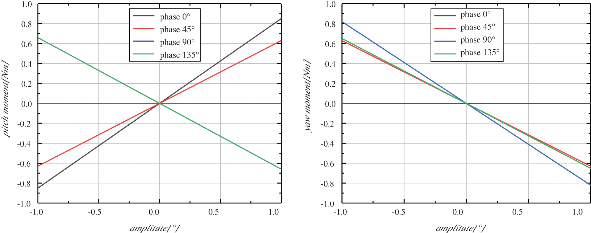
Figure 5: Curves of yaw and pitch moments changing with amplitude under different phases
Besides, Chujo et al. [43] adopted a pitch control technology in the combination of proportional and differential control. By adjusting two weight factors: the rotating speed of the rotor and the movement of the platform, the stability could be effectively improved and the fatigue load was reduced. This method had been verified in a scale model experiment of the National Maritime Research Institute (NMRI). Most of the existing literatures study the pitch angle control strategy, but the yaw system can adjust the amount of the wind energy capture and the yaw torque, which is often ignored by researchers. At present, the wind power generation system usually uses a wind direction measuring device at the top of the turbine to complete the yaw control, and Song et al. [44] gave a Model Prediction Control (MPC) based on a multi-step prediction model of the yaw system, which controlled the power output by coordinating the steps of a yaw controller and the value of a weight factor. In addition to the change of environmental conditions, the steps of the controller also determined the load value to a certain extent, so as to reduce the aerodynamic load. Regardless of the above-mentioned methods, Ding et al. [45] installed a Tuned Mass Damper (TMD) in the nacelle. By changing the mass, the amplitude of the surge and pitch motion could be significantly adjusted, the amplitude of the load fluctuation could be reduced and the stability was improved. This idea came initially from high-rise buildings, but it still needs experimental verifications to apply it to FOWT.
In addition to the mentioned contents, there are also some key scientific problems waiting to be solved by more researchers, here makes a simple list.
The structural strength and stability of the mooring system, as well as its disturbance to the platform motion, are also an important part. The mooring system has a great influence on the anti-overturning moment of the platform; the dense surrounding structures restrict the mooring radius and its arrangement direction; the high construction and installation costs directly affect the economy; the shallower the installation area of the mooring catenary, the greater the tension response under the same displacement, etc. When the tension is calculated by the numerical method, the quasi-static method based on the catenary equation or the dynamic method of finite element is used. The top motion of cable is taken as input, and the platform motion is calculated iteratively until convergence. Hong et al. [46] studied the influence of the mooring cable spring constant and the fairlead position in the scale model pool test, and verified it with simulation results. In the wave test, the above parameters would significantly increase the vibration of the platform near a certain natural frequency and even caused the fluid separation. Duan et al. [47] conducted a pool experiment on the wind turbine scale model of the Spar floating platform. The results showed that the wind-wave load had a serious impact on the coupling motion of pitch and heave, and further changed the tension fluctuation of the mooring system. Suzuki et al. [48] used the coupling analysis codes developed by Tokyo University to obtain the elastic response under the mooring traction, and analyzed the tension and load transfer mechanism of catenaries. Chen et al. [49] used the wave-current combination model to analyze the fatigue load of the mooring system, and found that the velocity and direction of the current would affect the tension of the mooring cable. If neglected, the fatigue life of the cable might be overestimated. Shen et al. [19] analyzed the tension distribution of the catenary moored by the deep buried anchor chain by a numerical method. The process was carried out under the seabed conditions of the sandy soil and the clayey soil respectively, which showed that the long-term horizontal displacement of the fairlead and the heave motion of the platform would change the inclination angle of the mooring line in the purchased soil, and the shear force of the soil and the tension of the catenary would increase continuously. The above simulations and tests have analyzed the load transfer mechanism of mooring system under specific seabed and floating platform, and obtained some meaningful qualitative conclusions. In order to reach the final design specification, it needs to constantly try and explore.
The motion response of the floating platform under the coupling mechanism of multiple physical fields needs to be clarified. The complex motion states can be explained by the typical six degrees of freedom: heave, sway, surge, pitch, roll and yaw [50]. Researchers have paid attention to the instability of wind-wave disturbance, studied the performance and motion responses, established multi-field physical models, and revealed the aero-hydro-servo-floater coupling mechanism [51]. Jonkman [52] developed a full coupling simulation tool integrating the main functions of FAST, AeroDyn, HydroDyn and others in 2007. The dynamic response and extreme load of the Barge type floating wind turbine system were analyzed, and this provided a reference for other researches. Wu et al. [53] used SESAM to establish the wind module and Morrison equation in 2012, and calculated the time history curve and response spectrums of FOWT supported by the Semi-Sub platform. The conclusion was that the wave frequency mainly affected the pitch motion, the resonance frequency of wave and floater affected the heave motion. This platform could significantly reduce the heave motion and delay the period of resonance, similar results are also obtained by Choi et al. [54]. Meng et al. [55] used FAST code to establish coupling model for each part, and set the system under different design resistance conditions. Part of the analysis results showed that the average dynamic response was mainly affected by wind induced during the operation, and the bending moment of tower head and tail, the vibration of platform pitch and the tension of mooring were mainly induced by wave. This paper did not give the data of the comparison between the simulation results and the ocean engineering pool experiments. In addition, some new codes have been developed to calculate the motion characteristics of the coupled model [56,57]. Although many people have done a variety of researches and summaries on the motion response under the multi field coupling, there is still no conclusion from qualitative to quantitative.
The accurate measurement of wind resource in the deep sea [58] and the design environment and design conditions of FOWT have not formed a unified standard and specification. In the process, it is more the case that the existing reference standard of the fixed wind turbine design is applied. However, there is not much data base and experience accumulation for the degree of the damage of FOWT caused by the extremely bad weather such as salt haze, thunderstorm, typhoon and so on. Therefore, a complete, universal and reliable engineering design standard of the floating wind power is urgently needed to be put forward.
At present, there is not a complete intelligent control system for FOWT to realize accurate prediction and remote control [58], thus the cost of operation and maintenance is greatly need to be reduced. Whether through the establishment of a fixed maintenance base for offshore wind farms on nearby islands, or the establishment of a maintenance ship convenient for the far-reaching farm, or considering the construction of helicopter landing point, the convenience can be improved, and the time can be shortened. So the standard of operation and maintenance risk managements of the floating wind farm needs to be formulated.
The planning and installation of submarine cables is also a technical challenge. The trade-off between DC or AC transmission modes in terms of feasibility and economy is the key. And there are lots of uncertainties in the access of wind farms to the power system, such as the technical risk of long-distance transmission, the cost demand for the construction of offshore booster stations, the synchronous matching of offshore wind farms and access systems, etc.
Although FOWT has been operating in some coastal countries, it still has a series of problems such as cost, control, operation and maintenance. This has caused more people to participate in this research, which focus on a scale design of the model, flow field characteristics, aerodynamic load fluctuation controls and so on. Due to the lack of design specifications, most of papers are based on existing theories and experience to obtain convincing results. Therefore, in the future work, we should strengthen the combination of experiment and theory to provide design criterions and technical supports for the future development of the floating offshore wind power technology.
With the rapid increase of turbine size, the scale ratio of scaling design process increases significantly, resulting in an formation of “size effect”, and Reynolds number can not be similar any more. Blade reconstruction is an important support for the theory of Froude number similarity and thrust coefficient similarity. In this process, it is the key to balance the thrust coefficient and power coefficient.
FOWT operates at a higher wind velocity and less turbulence environment. The interaction between wind turbines, the tilt motion can also keep the turbine in their own wake and this can reduce the output of downstream turbine by nearly 30%. Research results of wake characteristics show that turbulence intensity can promote faster recovery of loss velocity. The leading edge protube, VGs and optimized blade can effectively increase the angle of attack and improve stall performance. The aerodynamic response is also very different from that of wind turbine with fixed foundation. On this basis, a new cyclic pitch angle control strategy is proposed to reduce the pitch and yaw moment and fatigue load of FOWT. And it is expected to be applied to the actual operation to achieve high efficiency and load reduction.
No matter what control and implementation methods are adopted, it is the long cherished wish for FOWT to ensure the safety and reliability and achieve lower electricity costs in the future.
Acknowledgement: We would like to thank all those who have reviewed and contributed to this paper for their valuable assistance.
Funding Statement: The authors received no specific funding for this study.
Conflicts of Interest: The authors declare that they have no conflicts of interest to report regarding the present study.
1. WE (2019). Offshore wind in Europe: Key trends and statistics 2018. Brussels: Wind Europe. [Google Scholar]
2. GWEC (2021). Global wind report 2020. Brussels: Global Wind Energy Council. [Google Scholar]
3. Saha, C. S., Sefidan, M. A., Sojoudi, A. (2020). Performance and cost analysis of energy production from offshore wind turbines. Energy Engineering, 117(1), 41–47. DOI 10.32604/ee.2020.010412. [Google Scholar] [CrossRef]
4. IEA (2019). Offshore energy outlook. Brussels: International Energy Agency. [Google Scholar]
5. GWEC (2020). Global offshore wind report 2020. Brussels: Global Wind Energy Council. [Google Scholar]
6. WE (2019). Floating offshore wind vision statement. Brussels: Wind Europe. [Google Scholar]
7. Zhang, R., Tang, Y., Hu, J., Ruan, S., Chen, C. (2013). Dynamic response in frequency and time domains of a floating foundation for offshore wind turbines. Ocean Engineering, 60(2), 115–123. DOI 10.1016/j.oceaneng.2012.12.015. [Google Scholar] [CrossRef]
8. Roddier, D., Cermelli, C., Aubault, A., Weinstein, A. (2010). WindFloat: A floating foundation for offshore wind turbines. Journal of Renewable and Sustainable Energy, 2(3), 033104. DOI 10.1063/1.3435339. [Google Scholar] [CrossRef]
9. Liu, Y., Li, S., Yi, Q., Chen, D. (2016). Developments in semi-submersible floating foundations supporting wind turbines: A comprehensive review. Renewable and Sustainable Energy Reviews, 60, 433–449. DOI 10.1016/j.rser.2016.01.109. [Google Scholar] [CrossRef]
10. Tran, T. T., Kim, D. H. (2016). Fully coupled aero-hydrodynamic analysis of a semi-submersible FOWT using a dynamic fluid body interaction approach. Renewable Energy, 92(4), 244–261. DOI 10.1016/j.renene.2016.02.021. [Google Scholar] [CrossRef]
11. Yang, Y., Bashir, M., Michailides, C., Li, C., Wang, J. (2020). Development and application of an aero-hydro-servo-elastic coupling framework for analysis of floating offshore wind turbines. Renewable Energy, 161(1), 606–625. DOI 10.1016/j.renene.2020.07.134. [Google Scholar] [CrossRef]
12. Abdelsalam, A. M., El-Askary, W. A., Kotb, M. A., Sakr, I. M. (2021). Experimental study on small scale horizontal axis wind turbine of analytically-optimized blade with linearized chord twist angle profile. Energy, 216(5), 119304. DOI 10.1016/j.energy.2020.119304. [Google Scholar] [CrossRef]
13. Li, Q. A., Kamada, Y., Maeda, T., Murata, J., Iida, K. et al. (2016). Fundamental study on aerodynamic force of floating offshore wind turbine with cyclic pitch mechanism. Energy, 99(4), 20–31. DOI 10.1016/j.energy.2016.01.049. [Google Scholar] [CrossRef]
14. Bayati, I., Bernini, L., Zanotti, A., Belloli, M., Zasso, A. (2018). Experimental investigation of the unsteady aerodynamics of FOWT through PIV and hot-wire wake measurements. Journal of Physics: Conference Series, 1037, 052024. DOI 10.1088/1742-6596/1037/5/052024. [Google Scholar] [CrossRef]
15. Bayati, I., Facchinetti, A., Fontanella, A., Taruffi, F., Belloli, M. (2020). Analysis of FOWT dynamics in 2-DOF hybrid HIL wind tunnel experiments. Ocean Engineering, 195(1), 106717. DOI 10.1016/j.oceaneng.2019.106717. [Google Scholar] [CrossRef]
16. Harrold, M. J., Thies, P. R., Newsam, D., Ferreira, C. B., Johanning, L. (2020). Large-scale testing of a hydraulic non-linear mooring system for floating offshore wind turbines. Ocean Engineering, 206, 107386. DOI 10.1016/j.oceaneng.2020.107386. [Google Scholar] [CrossRef]
17. Kosasih, K. M. A., Suzuki, H., Niizato, H., Okubo, S. (2020). Demonstration experiment and numerical simulation analysis of full-scale barge-type floating offshore wind turbine. Journal of Marine Science and Engineering, 8(11), 880. DOI 10.3390/jmse8110880. [Google Scholar] [CrossRef]
18. Ruzzo, C., Fiamma, V., Collu, M., Failla, G., Nava, V. et al. (2018). On intermediate-scale open-sea experiments on floating offshore structures: Feasibility and application on a spar support for offshore wind turbines. Marine Structures, 61(2035), 220–237. DOI 10.1016/j.marstruc.2018.06.002. [Google Scholar] [CrossRef]
19. Shen, K., Guo, Z., Wang, L. (2018). Prediction of the whole mooring chain reaction to cyclic motion of a fairlead. Bulletin of Engineering Geology and the Environment, 78(4), 2197–2213. DOI 10.1007/s10064-018-1300-z. [Google Scholar] [CrossRef]
20. Utsunomiya, T., Matsukuma, H., Minoura, S., Ko, K., Hamamura, H. et al. (2013). At sea experiment of a hybrid spar for floating offshore wind turbine using 1/10-scale model. Journal of Offshore Mechanics and Arctic Engineering, 135(3), 268. DOI 10.1115/1.4024148. [Google Scholar] [CrossRef]
21. Bayati, I., Belloli, M., Bernini, L., Zasso, A. (2017). Aerodynamic design methodology for wind tunnel tests of wind turbine rotors. Journal of Wind Engineering and Industrial Aerodynamics, 167(6), 217–227. DOI 10.1016/j.jweia.2017.05.004. [Google Scholar] [CrossRef]
22. Souto-Iglesias, A., Lopez-Pavon, C., Valea-Peces, A., Soriano-Gomez, C., Rios-Tubio, J. et al. (2020). Scale effects on heave plates for semi-submersible floating offshore wind turbines: Case study with a solid plain plate. Journal of Offshore Mechanics and Arctic Engineering, 142(3), 345. DOI 10.1115/1.4045374. [Google Scholar] [CrossRef]
23. Meng, L., He, Y. P., Zhao, Y. S., Yang, J., Yang, H. et al. (2020). Dynamic response of 6 MW spar type floating offshore wind turbine by experiment and numerical analyses. China Ocean Engineering, 34(5), 608–620. DOI 10.1007/s13344-020-0055-z. [Google Scholar] [CrossRef]
24. Bayati, I., Belloli, M., Bernini, L., Mikkelsen, R., Zasso, A. (2016). On the aero-elastic design of the DTU 10 MW wind turbine blade for the LIFES50+ wind tunnel scale model. Journal of Physics: Conference Series, 753, 022028. DOI 10.1088/1742–6596/753/2/022028. [Google Scholar] [CrossRef]
25. Bayati, I., Facchinetti, A., Fontanella, A., Belloli, M. (2018). 6-DoF hydrodynamic modelling for wind tunnel hybrid/HIL tests of FOWT: The real-time challenge. Ocean Renewable Energy, 10, V010T09A078. DOI 10.1115/OMAE2018-77804. [Google Scholar] [CrossRef]
26. Fontanella, A., Liu, Y., Azcona, J., Pires, O., Bayati, I. et al. (2020). A hardware-in-the-loop wave-basin scale-model experiment for the validation of control strategies for floating offshore wind turbines. Journal of Physics: Conference Series, 1618, 032038. DOI 10.1088/1742-6596/1618/3/032038. [Google Scholar] [CrossRef]
27. Jang, H. K., Park, S., Kim, M. H., Kim, K. H., Hong, K. (2019). Effects of heave plates on the global performance of a multi-unit floating offshore wind turbine. Renewable Energy, 134, 526–537. DOI 10.1016/j.renene.2018.11.033. [Google Scholar] [CrossRef]
28. Ahn, H., Shin, H. (2020). Experimental and numerical analysis of a 10 MW floating offshore wind turbine in regular waves. Energies, 13(10), 2608. DOI 10.3390/en13102608. [Google Scholar] [CrossRef]
29. Li, Q. A., Murata, J., Endo, M., Maeda, T., Kamada, Y. (2016). Experimental and numerical investigation of the effect of turbulent inflow on a Horizontal Axis Wind Turbine (Part I: Power performance). Energy, 113(2), 713–722. DOI 10.1016/j.energy.2016.06.138. [Google Scholar] [CrossRef]
30. Li, Q. A., Murata, J., Endo, M., Maeda, T., Kamada, Y. (2016). Experimental and numerical investigation of the effect of turbulent inflow on a Horizontal Axis Wind Turbine (Part II: Wake characteristics). Energy, 113(4), 1304–1315. DOI 10.1016/j.energy.2016.08.018. [Google Scholar] [CrossRef]
31. Li, Q., Maeda, T., Kamada, Y., Mori, N. (2017). Investigation of wake effects on a Horizontal Axis Wind Turbine in field experiments (Part I: Horizontal axis direction). Energy, 134(1), 482–492. DOI 10.1016/j.energy.2017.05.187. [Google Scholar] [CrossRef]
32. Li, Q. A., Maeda, T., Kamada, Y., Mori, N. (2017). Investigation of wake characteristics of a Horizontal Axis Wind Turbine in vertical axis direction with field experiments. Energy, 141(1), 262–272. DOI 10.1016/j.energy.2017.09.079. [Google Scholar] [CrossRef]
33. Li, Q. A., Kamada, Y., Maeda, T., Nishida, Y. (2017). Experimental investigations of boundary layer impact on the airfoil aerodynamic forces of Horizontal Axis Wind Turbine in turbulent inflows. Energy, 135(11), 799–810. DOI 10.1016/j.energy.2017.06.174. [Google Scholar] [CrossRef]
34. Tahani, M., Maeda, T., Babayan, N., Mehrnia, S., Shadmehri, M. et al. (2017). Investigating the effect of geometrical parameters of an optimized wind turbine blade in turbulent flow. Energy Conversion and Management, 153, 71–82. DOI 10.1016/j.enconman.2017.09.073. [Google Scholar] [CrossRef]
35. Cai, C., Zuo, Z., Maeda, T., Kamada, Y., Li, Q. A. et al. (2017). Periodic and aperiodic flow patterns around an airfoil with leading-edge protuberances. Physics of Fluids, 29(11), 115110. DOI 10.1063/1.4991596. [Google Scholar] [CrossRef]
36. Zhao, Z., Luo, L., Qiu, D., Wang, S., Wang, Z. et al. (2021). On the topology of vortex structures and heat transfer of a gas turbine blade internal tip with different arrangement of delta-winglet vortex generators. International Journal of Thermal Sciences, 160(1), 106676. DOI 10.1016/j.ijthermalsci.2020.106676. [Google Scholar] [CrossRef]
37. Tran, T., Kim, D., Song, J. (2014). Computational fluid dynamic analysis of a floating offshore wind turbine experiencing platform pitching motion. Energies, 7(8), 5011–5026. DOI 10.3390/en7085011. [Google Scholar] [CrossRef]
38. Chen, Z., Wang, X., Guo, Y., Kang, S. (2021). Numerical analysis of unsteady aerodynamic performance of floating offshore wind turbine under platform surge and pitch motions. Renewable Energy, 163, 1849–1870. DOI 10.1016/j.renene.2020.10.096. [Google Scholar] [CrossRef]
39. Wang, X., Ye, Z., Kang, S., Hu, H. (2019). Investigations on the unsteady aerodynamic characteristics of a horizontal-axis wind turbine during dynamic yaw process. Energies, 12(16), 3124. DOI 10.3390/en12163124. [Google Scholar] [CrossRef]
40. Xu, B. F., Wang, T. G., Yuan, Y., Cao, J. F. (2015). Unsteady aerodynamic analysis for offshore floating wind turbines under different wind conditions. Philosophical Transactions of the Royal Society A: Mathematical, Physical and Engineering Sciences, 373(2035), 20140080. DOI 10.1098/rsta.2014.0080. [Google Scholar] [CrossRef]
41. Yang, J. J., He, E. M. (2020). Coupled modeling and structural vibration control for floating offshore wind turbine. Renewable Energy, 157(1), 678–694. DOI 10.1016/j.renene.2020.05.075. [Google Scholar] [CrossRef]
42. Sang, L. Q., Takao, M., Kamada, Y., Li, Q. A. (2017). Experimental investigation of the cyclic pitch control on a horizontal axis wind turbine in diagonal inflow wind condition. Energy, 134, 269–278. DOI 10.1016/j.energy.2017.06.042. [Google Scholar] [CrossRef]
43. Chujo, T., Minami, Y., Nimura, T., Ishida, S. (2013). Experimental study for spar type floating offshore wind turbine with blade-pitch control. 32nd ASME International Conference on Ocean, Offshore and Arctic EngineeringNantes, France. [Google Scholar]
44. Song, D. R., Li, Q. A., Cai, Z., Li, L., Yang, J. et al. (2019). Model predictive control using multi-step prediction model for electrical yaw system of Horizontal-Axis Wind Turbines. IEEE Transactions on Sustainable Energy, 10(4), 2084–2093. DOI 10.1109/TSTE.2018.2878624. [Google Scholar] [CrossRef]
45. Ding, Q. W., Li, C., Cheng, S. S., Hao, W. X., Huang, Z. Q. et al. (2019). Study on TMD control on stability improvement of Barge-supported floating offshore wind turbine based on the multi-island genetic algorithm. China Ocean Engineering, 3, 309–321. [Google Scholar]
46. Hong, S., Lee, I., Park, S. H., Lee, C., Chun, H. H. et al. (2015). An experimental study of the effect of mooring systems on the dynamics of a SPAR buoy-type floating offshore wind turbine. International Journal of Naval Architecture and Ocean Engineering, 7(3), 559–579. DOI 10.1515/ijnaoe-2015-0040. [Google Scholar] [CrossRef]
47. Duan, F., Hu, Z., Niedzwecki, J. M. (2016). Model test investigation of a spar floating wind turbine. Marine Structures, 49(1), 76–96. DOI 10.1016/j.marstruc.2016.05.011. [Google Scholar] [CrossRef]
48. Suzuki, H., Xiong, J., do Carmo, L. H. S., Vieira, D. P., de Mello, P. C. et al. (2018). Elastic response of a light-weight floating support structure of FOWT with guywire supported tower. Journal of Marine Science and Technology, 24(4), 1015–1028. DOI 10.1007/s00773-018-0614-7. [Google Scholar] [CrossRef]
49. Chen, L., Basu, B. (2018). Fatigue load estimation of a spar-type floating offshore wind turbine considering wave-current interactions. International Journal of Fatigue, 116(12), 421–428. DOI 10.1016/j.ijfatigue.2018.06.002. [Google Scholar] [CrossRef]
50. Le, C., Li, Y., Ding, H. (2019). Study on the coupled dynamic responses of a submerged floating wind turbine under different mooring conditions. Energies, 12(3), 418. DOI 10.3390/en12030418. [Google Scholar] [CrossRef]
51. Goupee, A. J., Koo, B. J., Kimball, R. W., Lambrakos, K. F., Dagher, H. J. (2014). Experimental comparison of three floating wind turbine concepts. Journal of Offshore Mechanics and Arctic Engineering, 136(2), 033104. DOI 10.1115/1.4025804. [Google Scholar] [CrossRef]
52. Jonkman, J. M. (2007). Dynamics modeling and loads analysis of an offshore floating wind turbine (Ph.D. ThesisUniversity of Colorado, Boulder. [Google Scholar]
53. Wu, H. T., Jiang, J., Zhao, J., Ye, X. R. (2012). Dynamic response of a semi-submersible floating offshore wind turbine in storm condition. Applied Mechanics and Materials, 260–261, 273–278. DOI 10.4028/www.scientific.net/AMM.260-261.273. [Google Scholar] [CrossRef]
54. Choi, E. Y., Cho, J. R., Cho, Y. U., Jeong, W. B., Lee, S. B. et al. (2015). Numerical and experimental study on dynamic response of moored spar-type scale platform for floating offshore wind turbine. Structural Engineering and Mechanics, 54(5), 909–922. DOI 10.12989/sem.2015.54.5.909. [Google Scholar] [CrossRef]
55. Meng, L., He, Y., Zhou, T., Zhao, Y., Liu, Y. (2018). Research on dynamic response characteristics of 6 MW spar-type floating offshore wind turbine. Journal of Shanghai Jiaotong University (Science), 23(4), 505–514. DOI 10.1007/s12204-018-1972-3. [Google Scholar] [CrossRef]
56. Bae, Y. H., Kim, M. H. (2014). Coupled dynamic analysis of multiple wind turbines on a large single floater. Ocean Engineering, 92(1), 175–187. DOI 10.1016/j.oceaneng.2014.10.001. [Google Scholar] [CrossRef]
57. Barooni, M., Ale Ali, N., Ashuri, T. (2018). An open-source comprehensive numerical model for dynamic response and loads analysis of floating offshore wind turbines. Energy, 154(1), 442–454. DOI 10.1016/j.energy.2018.04.163. [Google Scholar] [CrossRef]
58. IEA (2017). Expert group report on recommended practices: 18. Floating lidar systems. Brussels: International Energy Agency. [Google Scholar]
 | This work is licensed under a Creative Commons Attribution 4.0 International License, which permits unrestricted use, distribution, and reproduction in any medium, provided the original work is properly cited. |