| Energy Engineering |
DOI: 10.32604/EE.2022.016439
ARTICLE
Initiation Mechanism of Transverse Cracks in Wind Turbine Blade Trailing Edge
1School of Mechanical Engineering, Shandong University of Technology, Zibo, 255049, China
2China General Certification Center, Beijing, 100013, China
*Corresponding Author: Xuemei Huang. Email: huangxuemei@sdut.edu.cn
Received: 05 March 2021; Accepted: 28 June 2021
Abstract: Transverse crack often occurs in the trailing edge region of the blade when subjected to the excessive edgewise fatigue load. In this paper a refined model was established through local mesh refinement methods in order to investigate the initiation mechanism of crack and its extension in blade trailing edge. The material stress around the crack in trailing edge region under different thicknesses is calculated based on the fracture mechanics theory. The factors affecting the fatigue robustness of blade trailing edge are concluded by investigating the results of finite element analysis and coupons test. Compared with the laminate, the lower fatigue strength of the adhesive is the cause of the transverse crack of the adhesive joint at the trailing edge. The increase of the adhesive thickness at the adhesive joint will significantly increase the stress concentration factor at the crack region and accelerate the crack extension of the laminate. In final, a practical design scheme to prevent crack initiation is given for the manufacture of the wind turbine blade.
Keywords: Fatigue crack initiation; fracture mechanism; structure optimization; composite laminates; bonding joints; finite element method
Wind energy is expected to become one of the alternative energy to replace fossil energy in the process of reducing global warming. With the expansion of blade markets in recent years, blade manufacturers adopt the method of reducing blade weight to cut down the costs. The design department introduces a better geometrical form for blades based on Glass Fiber Reinforced Plastic (GFRP) through material and structure optimization. So, standards for testing blade performance are also being added to identify the robustness of the new lightweight blade [1–4].
In general, the design life of a wind turbine is 20–25 years. During its work condition, the blade is regularly subjected to a combined load, resulting in a large fatigue load or even blade failure [5]. So, accurate structural design and strength tests [6–11] of the blade are reasonably required in order to ensure the robust performance of the blade in its life. In recent studies, Chen [12] conducts the fatigue test of the blade through the full-scale tests method, and he reports the development rule of materials performance and fatigue life of the blade under cyclic load. Castro et al. [13] studies the stress response of Glass Fiber Fabric (GFF) with cracks under cyclic load and notes that the GFF with defects under a lower load level would not produce more cracks, but extends the existing cracks; the GFF with defects under a higher load level would produce more cracks around the existing cracks. More conclusions of the blade fatigue test are reported in the work of Greaves [14].
Based on previous research, blade manufacturers noticed that the transverse crack defects (Fig. 1a) are often generated in the blade trailing edge after a large number of fatigue tests. Similarly, the blade operating on the wind turbine tower is often damaged by cracks before reaching its design life (Fig. 1b). The blade trailing edge is a shell structure bonded by adhesive. In the middle and leading segment of the blade shell, there are only 2–6 multiaxial GFF layers, which is a little weak. Due to the poor capacity of fatigue performance of bonding structure, it is damage easily when loaded by fatigue forces. Then stress concentration would be caused in the adhesive of trailing edge, making the trailing edge strength decrease and cracks easily.
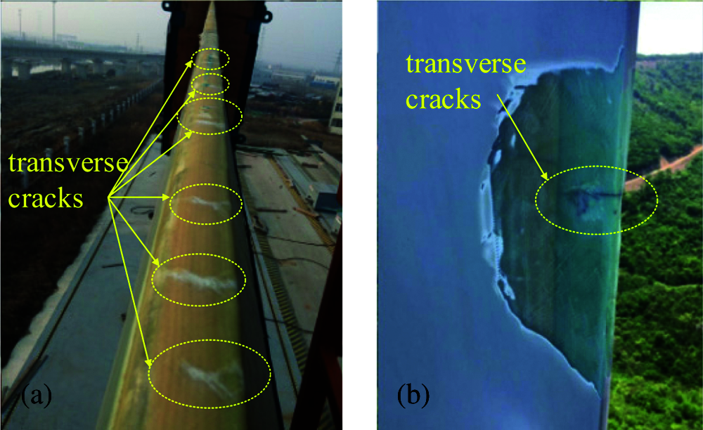
Figure 1: Cracks defect in the blade (a) Defective blade in fatigue test, (b) Defective blade in wind turbine tower
In the failure mechanism research of blade trailing edge, Chen et al. [15] conducts a subcomponent test and points out that the trailing edge collapsed with adhesive joint and sandwich when subjected to the ultimate edgewise load. Bender et al. [16] studies the strength of adhesive joint and finds that the adhesive joint structure with defects has a significant reduction comparing with intact subcomponent in performance. Therefore, transverse cracks have some influence on the structural strength of the trailing edge. Eder et al. [17] conducts a test for adhesive joint strength and finds that the effect of different bonding structures on the adhesive joint performance of the adhesive joint is different. Further research on the effect of defects on subcomponent structure can be found in the reports of Ji et al. [18] and Fernandez et al. [19].
The failure mode of trailing edge is complex and multitudinous. In the only article mentioning the blade transverse cracks, Ataya et al. [20] has notes the forms and locations of transverse cracks in blades without giving a failure mechanism.
The focus of this paper is placed on the crack defects in the blade trailing edge based on the research of [20]. The influence factors of transverse crack initiation and extension were studied with different adhesive thicknesses at the joint. For that, a refined Finite Element (FE) model of the trailing edge is established. Then the influence of different bonding parameters on the extension of defects and the development rule of crack under fatigue load is determined. According to the test standard of blade material [21–23] and Fernandez's test method in [19], the specimens with defects are made for coupons test. The fatigue load is applied to the specimens, and then the test results are collected to verify the simulation results obtained in Section 3. Finally, the initiation mechanism of transverse cracks in the blade trailing edge under fatigue load is concluded thoughtfully.
2 Descriptions of the Blade Section
The typical wind turbine blade is a shell structure (see Fig. 2), and its shape has aerodynamic performance. It is usually made of two half-shells of Pressure Side (PS) and Suction Side (SS). Adhesive joints are designed at the leading edge and trailing edge of the blade, and the two half-shells are bonded together by bonding paste. The spar cap placed in the middle of shells, and the shear web fixed in the middle of spar cap constitutes the box-beam structure. The blade is subjected to the flapwise load caused by wind pressure and edgewise load caused by gravitational. And the box-beam is the major part to carry flapwise load which is generated by 70% gravitational force and 30% aerodynamic load.
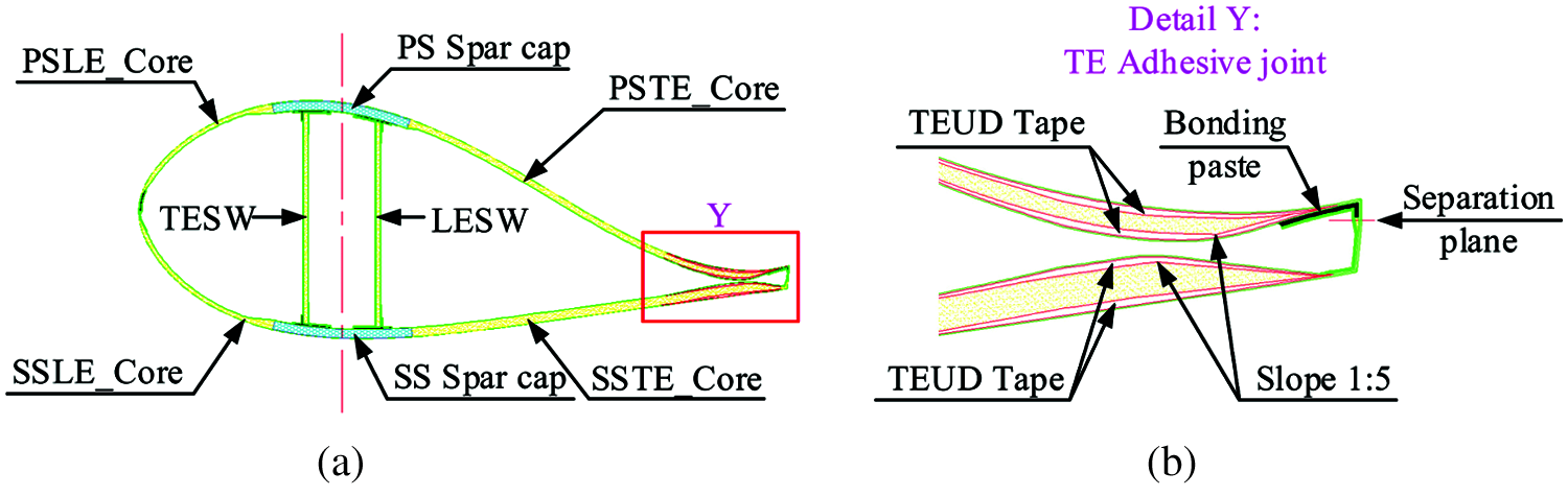
Figure 2: The structure of blade trailing edge (LE: leading edge, SW: shear web, TE: trailing edge) (a) Section structure of wind turbine blade (b) Details of blade trailing edge
The whole blade section is divided into leading edge and trailing edge based on the dividing line in the middle of the web shear. Among them, the trailing edge mainly bears the tension-compression cyclic load. In order to enhance its fatigue performance, a Unidirectional (UD) tape structure is placed in the trailing edge region of two shells. UD tape is the minor part to carry the edgewise load.
Multilayer triaxial GFF in trailing edge is set on the shell of the blade root region to carry the load accumulated from the global blade. Another part of the shell is a sandwich structure composed of 2–3 layers of multi-axial GFF and balsa wood so that the global structure of the blade has appropriate stiffness to resist deformation.
At present, the shell of PS and SS of trailing edge are manufactured separately, and a bonding structure is designed to bond the two shells. The type of bonding structure is usually in the form of socket, bonding lip, and direct bonding (see Fig. 3, a is from the blade adhesive joint of GW59.5, and b is from the blade adhesive joint of LZ40.3). Its type is selected according to the size of trailing edge.

Figure 3: Bonding structure of blade trailing edge (a) Socket at blade trailing edge, (b) Bonding lip at blade trailing edge
The cumulative fatigue damage caused by cyclic load leads to the failure of the material and results in the crack defects shown in Fig. 1. The generation of cracks experienced three stages: crack initiation, stable crack extension, and fracture. In the finite element method used in this project, the global fatigue life of the blade can be divided into two parts: crack initiation life and crack growth life.
The adhesive used in the bonding paste is a brittle material, and it has a poor fatigue performance. The fatigue load causes the crack in bonding paste, and then the crack gradually extends to the complete fracture. There is a notch effect between the bonding paste and laminate at the crack region. The notch effect raises the local stress of laminate and accelerates the process of fatigue failure, and finally, notch effect produces transverse cracks at the blade trailing edge. In this paper, the coefficient of elastic stress concentration Kt is used to describe the crack defects.
where, σ is the maximum stress at crack region. S is the nominal stress at crack region.
Evaluation of blade life needs the fatigue load value [21,24]. The fatigue load of the blade trailing edge can be gained by combining the simulation software “Bladed” and Finite Element Method (FEM). The maximum fatigue life of related materials under different stress amplitudes and average values can be calculated according to the Goodman formula represented by Eq. (3).
According to the corresponding cycle number provided by Eq. (3), the Miner linear fatigue damage cumulative rule expressed by Eq. (4) can be used to evaluate the fatigue life of tested blade.
The FEM can reduce the expenses of blade design and optimization. So a refined model of the blade was established in order to investigate the initiation mechanism of the transverse crack under different bonding scales in the blade trailing edge.
The classic wind turbine blade is a shell structure. Using shell elements for blade modeling can accurately calculate the global stress distribution and deformation of the blade. However, the blade trailing edge has a complex bonding structure. The shell element modeling method simplifies the structure details of the adhesive joint, which is hard to gain accurate local stress of blade trailing edge. Besides, the solid element modeling method needs a large number of the solid element which needs a complicated calculation. The blade layer structure is complex, so it is hard to build a refined model using the shell or solid elements.
In order to solve this problem, hybrid shell-solid elements are used to model the trailing edge. The blade of LZ40.3 is selected as the analysis subject. The shell element (S8R element) model for the blade and the solid element (C3D8R element) model for the blade trailing edge is created. Firstly, the whole model is calculated, and the displacement data of shell element nodes is collected. Then the displacement data set as the boundary conditions and maps to the subcomponent composed of solid elements, as shown in Fig. 4.
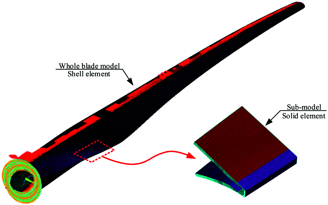
Figure 4: The refined FE model of blade
According to the different thicknesses of the bonding paste mentioned in Section 2.1, the finite element model (Fig. 5) is established.
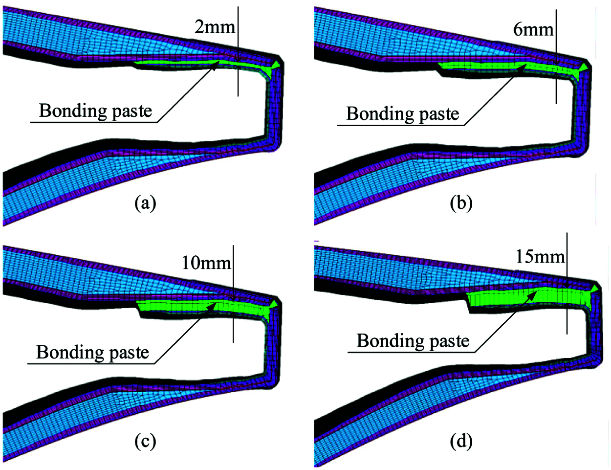
Figure 5: Solid element model with different bonding paste thickness (a) With thickness 2 mm, (b) With thickness 6 mm, (c) With thickness 10 mm, (d) With thickness 15 mm
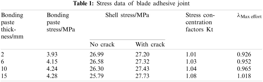
By establishing the trailing edge model with different bonding thicknesses, the local stress distribution of the adhesive joint with a crack at the trailing edge is simulated, respectively. Finally, a reasonable explanation is given. It can be seen from Fig. 6 that: the laminate crack causes stress redistribution in the crack region of the blade trailing edge, and different bonding parameters lead to different stress distribution. The stress concentration factors of adhesive joint models with different thicknesses are obtained by extracting the element stress in the crack region, see Table 1. The stress concentration factor is cited in the fatigue analysis of the blade trailing edge. Then the fatigue strength of the GFF material is calculated referring to the Markov matrix of the blade. In final, the influence of eigenvalue λ on the fatigue results of the trailing edge is collected under different stress concentration factors.
Kt represents the level of stress concentration of the crack regions. It can be seen from Table 1 that the stress concentration factor Kt and λ have a noticeable increase with the adding of adhesive thickness. It indicates that the stress contribution factor of bonding paste in global structure performance increases with adhesive thickness. The bonding paste absorbs a larger fatigue load when has a thicker adhesive. Simultaneously, laminate with cracks will release more stress and transfer to the surrounding laminate so that the adhesive joint can obtain a higher stress concentration factor, which makes the shell more prone to fatigue cracks.
The FE results show that when the bonding paste thickness adds, the fracture will cause a more serious local stress concentration, which makes the trailing edge shell has a higher probability of fatigue failure and transverse cracks. And the actual production shows that when the bonding paste is too thick in production, it is easy to produce internal stress and cavity defects in the curing process, which makes the bonding paste has a poor performance and fatigue strength. Therefore, better control of bonding paste thickness in its production is conducive to improve the strength of the trailing edge.
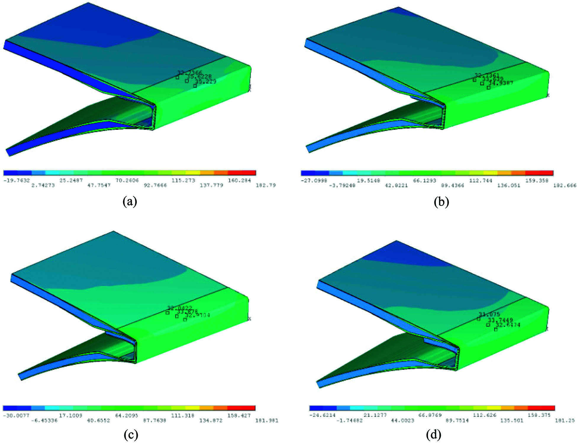
Figure 6: Simulation results of adhesive joint with different bonding paste thickness (a) With thickness 2 mm, (b) With thickness 6 mm, (c) With thickness 10 mm, (d) With thickness 15 mm
4 Coupons Test of Specimens with Adhesive
These five specimens (see Fig. 7) made of GFF and adhesive are prepared in the laboratory in order to further investigate the failure mechanism of the transverse crack on trailing edge and verify the results of FE simulation. The length, width, and height of the specimens are 150 mm, 16 mm, and 7.5 mm, respectively. Then the coupons test is conducted to simulate the bonding structure of blade trailing edge.
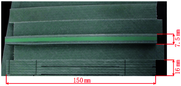
Figure 7: Laminate specimens of fatigue test
The coupons test is carried out on the compression-testing machine, both ends of the specimens are clamped by the independently designed tooling, and the strain gauge is pasted in the middle. The specimen is fixed on the machine, and the special clamp is used to apply pressure to the specimen along the fiber direction until it fails. The stress sensor is set on the press to collect the compressive strength of the specimen. By collecting the data of stress and strain, the composite properties and crack growth process was studied in detail. More detailed about composite performance of specimens and the process of crack extension are collected in this fatigue test.
Firstly, the static test is conducted to obtain the ultimate strength of the specimens. Then the load data under different cyclic loads is preliminarily estimated to determine the load spectrum of fatigue test. After that, the fatigue test is carried out. According to the stress and failure process of the specimens, the failure mechanism is deduced.
The static loading results of the sample are shown in Fig. 8. The ultimate strength values of the specimens measured by the test are 121/114/120/140/133 MPa in Fig. 9, with an average of 123.6 MPa.
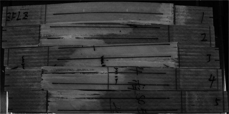
Figure 8: Fracture behavior of the specimens in static test
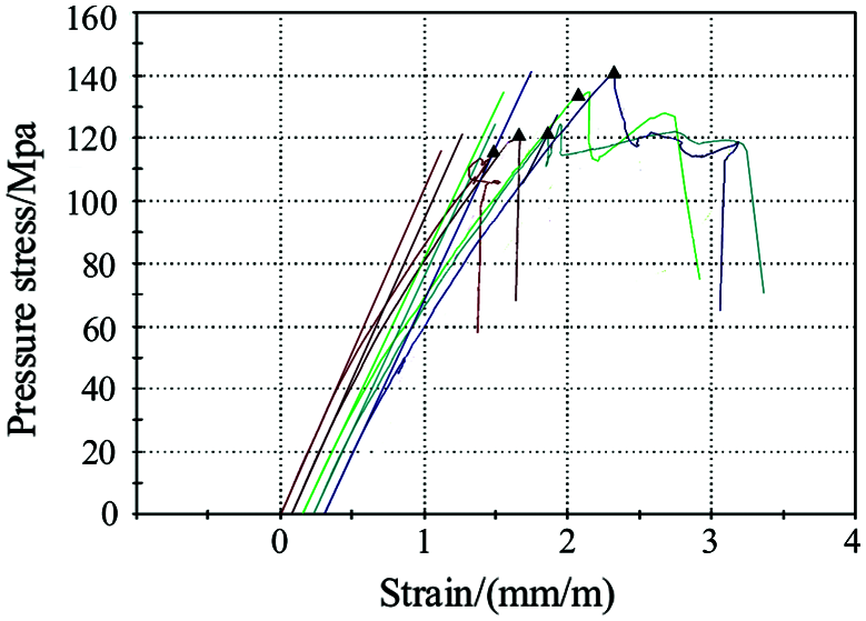
Figure 9: Stress data of the specimens in static test
In the fatigue test, the maximum value in the load spectrum is set as 40/50/60/80/100 MPa. The cyclic load was applied to the specimens with a stress ratio of 0.05 and a frequency of 1.02 Hz until it fails, and then the S-N data of the specimens are collected. The failure modes include laminate damage and adhesive crack in Fig. 10. More serious damage was done to the specimens when subjecting to the larger cyclic load, as shown in Fig. 11. The regions marked in Fig. 10 suffered minor damage at the time of failure. The S-N curve fitted according to the test results is linear, the fitting curve can express as y = 177.17x − 0.118.
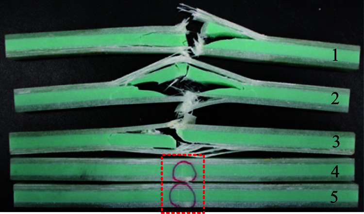
Figure 10: Fracture behavior of the specimens in fatigue test
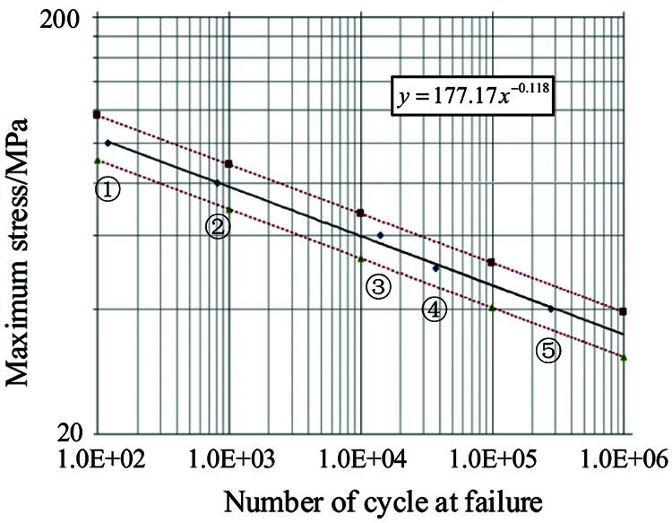
Figure 11: S-N data of tested specimens
Macroscopic observation of the test process shows that the initial cracks are always generated in adhesive under fatigue load. The stress concentration occurs around the crack region, which caused the crack extension of adhesive. In the crack extension process, the laminate on both sides of the crack is also damaged due to adhesive structure defects. The crack in laminate extends laterally, which reduces the global structural performance of the blade.
The trailing edge is a vulnerable part of the blade. Due to its high stiffness and low strength material performance, the adhesive has no ability to resist the stress transmitted by the trailing edge structure. So when the blade is subjected to low cycle fatigue load, the adhesive crack will be caused. The FE analysis and the coupons test are conducted in order to investigate the initiation mechanism of transverse crack at the blade trailing edge. Based on the simulation and test results, some conclusions can be drawn.
From the simulation and test results, it can be seen that the fatigue strength of the adhesive is weedier than that of GFF. Damage to adhesive is the major cause that makes the transverse appear at the adhesive joint. In actual production, when the adhesive thickness is too thick, cavity defects will be introduced in the production of the blade. It is easy to produce high internal stress and initial micro-cracks during the solidification process of adhesive, which will further reduce the fatigue strength of adhesive.
Adhesive cracks induce the final transverse cracks of laminates. In blade service life, cracks may occur in bonding paste. If the bonding paste is too thick, it will cause a larger stress concentration of the materials in the adhesive crack area, and the fatigue strength of the adhesive joint will be weakened. Then the transverse crack of the trailing edge will quickly extend, which will lead to the failure of the trailing edge.
There are two methods to avoid the transverse crack in the trailing edge: 1. Redesign the bonding paste of the trailing edge and reasonably determine the adhesive thickness in the blade production. 2. Adding GFF crack control layer in the laminate, which can reduce the stress concentration and improves the fatigue strength of the trailing edge. In the latest blade design, an anti-cracking layer is added to the shell at the trailing edge. After the blade fatigue test, there is no transverse crack on the trailing edge.
Acknowledgement: Conceptualization, J.W. and X.H.; methodology, X.H.; software, J.Z.; validation, J.W., L.Z. and X.H.; formal analysis, L.Z.; investigation, X.H.; resources, L.Z.; data curation, C.Y.; writing—original draft preparation, J.W.; writing—review and editing, Z.L.; visualization, J.Z.; supervision, C.Y.; project administration, X.H.; funding acquisition, L.Z. The article has been approved by all listed authors before submission.
Funding Statement: This research was funded by Natural Science Foundation of Shandong Province (Grant No. ZR2019MEE076) and National Natural Science Foundation of China (Grant No. 52075305).
Conflicts of Interest: The authors declare that they have no conflicts of interest to report regarding the present study.
1. Haselbach, P. U., Eder, M., Belloni, F. (2016). A comprehensive investigation of trailing edge damage in a wind turbine rotor blade. Wind Energy, 19, 1871–1888. DOI 10.1002/we.1956. [Google Scholar] [CrossRef]
2. Verma, A. S., Vedvik, N. P., Gao, Z. (2019). A comprehensive numerical investigation of the impact behaviour of an offshore wind turbine blade due to impact loads during installation. Ocean Engineering, 172, 127–145. DOI 10.1016/j.oceaneng.2018.11.021. [Google Scholar] [CrossRef]
3. Brunner, A. J. (2018). Identification of damage mechanisms in fiber-reinforced polymer-matrix composites with acoustic emission and the challenge of assessing structural integrity and service-life. Construction and Building Materials, 173, 629–637. DOI 10.1016/j.conbuildmat.2018.04.084. [Google Scholar] [CrossRef]
4. Papi, F., Cappugi, L., Salvadori, S., Carnevale, M., Bianchini, A. (2020). Uncertainty quantification of the effects of blade damage on the actual energy production of modern wind turbines. Energies, 13, 3785. DOI 10.3390/en13153785. [Google Scholar] [CrossRef]
5. Mishnaevsky, L., Branner, K., Petersen, H. N., Beauson, J., McGugan, M. et al. (2017). Materials for wind turbine blades: An overview. Materials, 10, 11. DOI 10.3390/ma10111285. [Google Scholar] [CrossRef]
6. Chen, X., Tang, J. Y., Yang, K. (2019). Modeling multiple failures of composite box beams used in wind turbine blades. Composite Structures, 217, 130–142. DOI 10.1016/j.compstruct.2019.03.018. [Google Scholar] [CrossRef]
7. Tang, J. Y., Chen, X. (2018). Experimental investigation on ultimate strength and failure response of composite box beams used in wind turbine blades. Composite Structures, 198, 19–34. DOI 10.1016/j.compstruct.2018.05.042. [Google Scholar] [CrossRef]
8. Haselbach, P. U., Branner, K. (2015). Effect of trailing edge damage on full-scale wind turbine blade failure. International Conference on Composite Materials, pp. 19–24. Copenhagen, Denmark. [Google Scholar]
9. Zhang, L., Guo, Y., Wang, J., Huang, X., Wei, X. et al. (2019). Structural failure test of a 52.5 m wind turbine blade under combined loading. Engineering Failure Analysis, 103, 286–293. DOI 10.1016/j.engfailanal.2019.04.069. [Google Scholar] [CrossRef]
10. Zuo, Y., Montesano, J., Singh, C. V. (2018). Assessing progressive failure in long wind turbine blades under quasi-static and cyclic loads. Renewable Energy, 119, 754–766. DOI 10.1016/j.renene.2017.10.103. [Google Scholar] [CrossRef]
11. Haselbach, P. U., Branner, K. (2016). Initiation of trailing edge failure in full-scale wind turbine blade test. Engineering Fracture Mechanics, 162, 136–154. DOI 10.1016/j.engfracmech.2016.04.041. [Google Scholar] [CrossRef]
12. Chen, X. (2019). Experimental observation of fatigue degradation in a composite wind turbine blade. Composite Structures, 212, 547–551. DOI 10.1016/j.compstruct.2019.01.051. [Google Scholar] [CrossRef]
13. Castro, O., Carraro, P. A., Maragoni, L., Quaresimin, M. (2019). Fatigue damage evolution in unidirectional glass/epoxy composites under a cyclic load. Polymer Testing, 74, 216–224. DOI 10.1016/j.polymertesting.2018.12.027. [Google Scholar] [CrossRef]
14. Greaves, P. R. (2013). Fatigue analysis and testing of wind turbine blades (Durham Theses). Durham University. [Google Scholar]
15. Chen, X., Berring, P., Madsen, S. H., Branner, K., Semenov, S. (2019). Understanding progressive failure mechanisms of a wind turbine blade trailing edge section through subcomponent tests and nonlinear FE analysis. Composite Structures, 214, 422–438. DOI 10.1016/j.compstruct.2019.02.024. [Google Scholar] [CrossRef]
16. Bender, J., Hallett, S. R., Lindgaard, E. (2019). Investigation of the effect of wrinkle features on wind turbine blade sub-structure strength. Composite Structures, 218, 39–49. DOI 10.1016/j.compstruct.2019.03.026. [Google Scholar] [CrossRef]
17. Eder, M., Bitsche, R. D. (2015). Fracture analysis of adhesive joints in wind turbine blades. Wind Energy, 18, 1007–1022. DOI 10.1002/we.1744. [Google Scholar] [CrossRef]
18. Ji, Y. M., Han, K. S. (2014). Fracture mechanics approach for failure of adhesive joints in wind turbine blades. Renewable Energy, 65(5), 23–28. DOI 10.1016/j.renene.2013.07.004. [Google Scholar] [CrossRef]
19. Fernandez, G., Usabiaga, H., Vandepitte, D. (2017). Subcomponent development for sandwich composite wind turbine blade bonded joints analysis. Composite Structures, 180, 41–62. DOI 10.1016/j.compstruct.2017.07.098. [Google Scholar] [CrossRef]
20. Ataya, S., Ahmed, M. (2013). Damages of wind turbine blade trailing edge: Forms, location, and root causes. Engineering Failure Analysis, 35, 480–488. DOI 10.1016/j.engfailanal.2013.05.011. [Google Scholar] [CrossRef]
21. Benzeggagh, M. L., Kenane, M. (1996). Measurement of mixed-mode delamination fracture toughness of unidirectional glass/epoxy composites with mixed-mode bending apparatus. Composites Science & Technology, 56(4), 439–449. DOI 10.1016/0266-3538(96)00005-X. [Google Scholar] [CrossRef]
22. Epaarachchi, J. A., Clausen, P. D. (2006). The development of a fatigue loading spectrum for small wind turbine blades. Journal of Wind Engineering & Industrial Aerodynamics, 94(4), 207–223. DOI 10.1016/j.jweia.2005.12.007. [Google Scholar] [CrossRef]
23. Eder, M. A., Chen, X. (2020). Fastigue: A computationally efficient approach for simulating discrete fatigue crack growth in large-scale structures. Engineering Fracture Mechanics, 233, 107075. DOI 10.1016/j.engfracmech.2020.107075. [Google Scholar] [CrossRef]
24. Fan, X., Sun, Q. (2011). Study on mixed-mode interlaminar fracture of laminated composites. Applied Mechanics and Materials, 110–116, 1345–1352. DOI 10.4028/www.scientific.net/AMM.110-116.1345. [Google Scholar] [CrossRef]
 | This work is licensed under a Creative Commons Attribution 4.0 International License, which permits unrestricted use, distribution, and reproduction in any medium, provided the original work is properly cited. |