| Energy Engineering |
DOI: 10.32604/EE.2022.017463
ARTICLE
Research on the Intelligent Control Strategy of the Fuel Cell Phase-Shifting Full-Bridge Power Electronics DC-DC Converter
1School of Electrical Engineering, Nantong University, Nantong, 226019, China
2School of Electrical and Power Engineering, China University of Mining and Technology, Xuzhou, 221116, China
*Corresponding Author: Yinlong Yuan. Email: yuanyl@ntu.edu.cn
Received: 12 May 2021; Accepted: 02 July 2021
Abstract: With the aggravation of energy problems, the development and utilization of new energy has become the focus of all countries. As an effective new energy, the fuel cell has attracted the attention of scholars. However, due to the particularity of proton exchange membrane fuel cell (PEMFC), the performance of traditional PI controlled phase-shifted full-bridge power electronics DC-DC converter cannot meet the needs of practical application. In order to further improve the dynamic performance of the converter, this paper first introduces several main topologies of the current mainstream front-end DC-DC converter, and analyzes their performance in the fuel cell system. Then, the operation process of the phase-shifted full-bridge power electronics DC-DC converter is introduced, and the shortcomings of the traditional PI control are analyzed. Finally, a double closed-loop adaptive fuzzy PI controller is proposed, which is characterized by dynamically adjusting PI parameters according to different working states to complete the intelligent control of phase-shifted full-bridge DC-DC converter. The simulation results in MATLAB/Simulink show that the proposed algorithm has good a control effect. Compared with the traditional algorithm, the overshoot and stabilization time of the system are shorter. The algorithm can effectively suppress the fluctuation of the output current of the fuel cell converter, and is a very practical control method.
Keywords: Phase-shifted full-bridge; adaptive fuzzy PI control; proton exchange membrane fuel cell; MATLAB/Simulink
Currently, with the development of society, people's demand for electricity is rising sharply. It plays an increasingly important role in human life. Nowadays, electricity is mainly generated from fossil fuels, such as gasoline, coal, natural gas, etc. Fossil fuels are not only limited in reserves, but also have a bad impact on the environment [1]. It is necessary to explore clean and reliable alternative energy, which does not rely on fossil fuels. These alternative energy sources include solar energy, wind energy, biomass energy, geothermal energy, tidal energy, hydropower, etc. The energy obtained from these sources is called renewable energy [2]. The advantage of renewable energy is that it is inexhaustible and will not pollute the environment. At present, all countries are focusing on the development of new energy technology [3]. New technologies for renewable energy systems are emerging [4]. Using fuel cell to generate electricity is one of the new energy technologies, whose power generation process will not disturb the environment [5]. Fuel cell is a promising device because it is efficient, modular and can be placed anywhere to improve system efficiency [6].
Because the proton exchange membrane fuel cell (PEMFC) has the characteristics of high-power density, fast start-up, light weight and low cost, it is more suitable for low-power, small-scale power generation [7–11]. Compared with traditional batteries, fuel cells have more fluctuating voltage changes during operation [12]. Therefore, it is of great significance to design a good DC-DC converter to improve the rapidity and stability of fuel cells generation system.
At present, the main DC-DC converter topology can be roughly divided into two types: non-isolated and isolated [13–19]. Several representative topologies of non-isolated DC converters include the buck circuit, the boost circuit, the buck-boost circuit, the cuk circuit, etc. The buck circuit can only be used to decrease the voltage, so it is not suitable for the preceding stage DC-DC converter of the fuel cell grid-connected power generation system. Although the boost circuit can increase the voltage, its voltage increase ratio is limited due to the limitation of duty cycle of power electronics devices. It is not also suitable. The buck-boost circuit can achieve both the voltage increase and the voltage decrease, but it is also limited by the duty cycle of power electronics devices, and its voltage increase ratio is also limited. The cuk circuit has the advantage of continuous input-output current, but its voltage decrease ratio is limited. They are not suitable for the DC-DC converter studied in this paper too.
Isolated DC-DC converters include the single-ended flyback circuit, the single-ended forward circuit, the half bridge DC-DC circuit, the full bridge DC-DC circuit, etc. The single-ended forward circuit uses a high-frequency transformer to achieve the electrical isolation and the voltage increase. However, it is generally not used in high power applications because of its high voltage stress and the magnetic reset problem. The single ended flyback circuit also uses a high-frequency transformer to achieve the electrical isolation and the voltage increase, but its disadvantages such as obvious output voltage ripple, high stress on power electronics devices and discontinuous output power limit the application in fuel cell preceding stage DC-DC converter. The half bridge DC-DC circuit uses the single-phase inverter circuit to convert the DC voltage to the AC voltage, which is amplified by the transformer and then output the DC voltage by the rectifier circuit and the filter circuit. The output voltage fluctuation of this topology is small, and the transformer is bi-directional excitation. It is more suitable for the preceding stage DC-DC converter of the fuel cell. However, the voltage utilization of its input side is only 50%. Moreover, there is the problem of input voltage sharing, so it needs to be improved. The full-bridge DC-DC circuit is adopted in this paper, which can avoid the problem of the input voltage balance, and the utilization rate of the input voltage rises to 100%.
The phase-shifted full-bridge DC-DC converter, as the key topology of the power conversion, has become the focus of the current research. There converter is often controlled by PI adjuster [20–24]. However, the control effect is often poor when the voltage source system is nonlinear and has uncertain parameters and structure. Therefore, how to change the existing controller structure and introduce intelligent control strategy to make the fuel cell generation system have the better dynamic response speed and the stability coefficient is an urgent and meaningful work.
PI control method is often used in the DC-DC converter, which is easy to implement. By controlling the current with negative feedback, not only the steady-state characteristics can be improved, but also the dynamic characteristics can be improved. After PI control processing, the quality of current is obviously improved and the noise pollution is reduced [25–27]. However, in order to have small steady-state error and system stability at the same time, it is necessary to adjust the parameters continuously to achieve a compromise. This problem can be solved by fuzzy PI control [28], a kind of intelligent control, which uses fuzzy reasoning to control the complex nonlinear system. In the design of fuzzy control system, we do not need to know the exact mathematical model of the controlled object, which is different from the traditional PI control method. Because there is no need to establish a precise mathematical model, the design of fuzzy control is easier and easy to be applied to various control systems [29,30].
In this paper, a double closed-loop adaptive fuzzy PI controller is proposed by analyzing the special performance of the fuel cell. According to different task states, PI parameters are dynamically adjusted to realize the intelligent control of the phase-shifting full-bridge DC-DC converter. The simulation results in MATLAB/Simulink show that the algorithm proposed in this paper has a better control effect. It can not only effectively control the output voltage of the DC-DC converter to be the set value with faster speed and low overshoot, but also enhance its anti-disturbance performance and reduce the output current ripple. In addition, compared with the traditional PI control, it can reduce the adjustment time and the fluctuation of the fuel cell output voltage when the system starts up.
The structure of the paper is as follows. Section 2 introduces the topology and the mathematical model of the full-bridge DC-DC converter. The traditional control algorithm of the DC-DC converter is analyzed in Section 3. Section 4 designs the adaptive double closed loop PI controller. Section 5 shows the simulation results. The paper is concluded in Section 6.
2 Topology and Mathematical Model of the Full-Bridge DC-DC Converter
2.1 Structure and Operation Principle
The full-bridge DC-DC converter is composed of the full-bridge inverter, the high-frequency transformer, the rectifier and the LC filter generally. As shown in Fig. 1, VT1, VT2, VT3, VT4 are IGBTs, VD1, VD2, VD3, VD4 are the corresponding antiparallel diodes; C1, C2, C3, C4 are the corresponding parasitic capacitance; Lk is the equivalent leakage inductance of the primary side of the high-frequency transformer; V1, V2 are the original input voltage and the secondary output voltage; i′ is the input current of the high-frequency transformer; N is the ratio of the transformer; Vin, Vout and i are the input voltage, the output voltage and the output current respectively; VD5, VD6, VD7, VD8 are the diodes of the rectifier bridge, which convert the AC voltage V2 into the DC voltage; L and C is the inductance and the capacitance of the LC filter; R is the equivalent resistance of the load; A and B are the middle point of the half bridges; C and D are the positive point and the negative point of the output bus; T is the high-frequency transformer.
The operation of the phase-shifted full-bridge DC-DC converter can be divided into eight subintervals. The waveform of each electric quantity during the operation of the converter is shown in Fig. 2, where, Vd1, Vd2, Vd3 and Vd4 are the driving signals, which is applied to the four IGBTs.
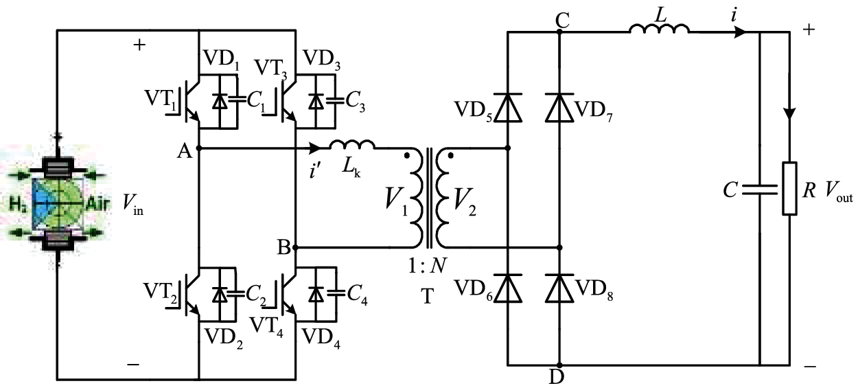
Figure 1: Topology diagram of a phase-shifting full-bridge DC-DC converter
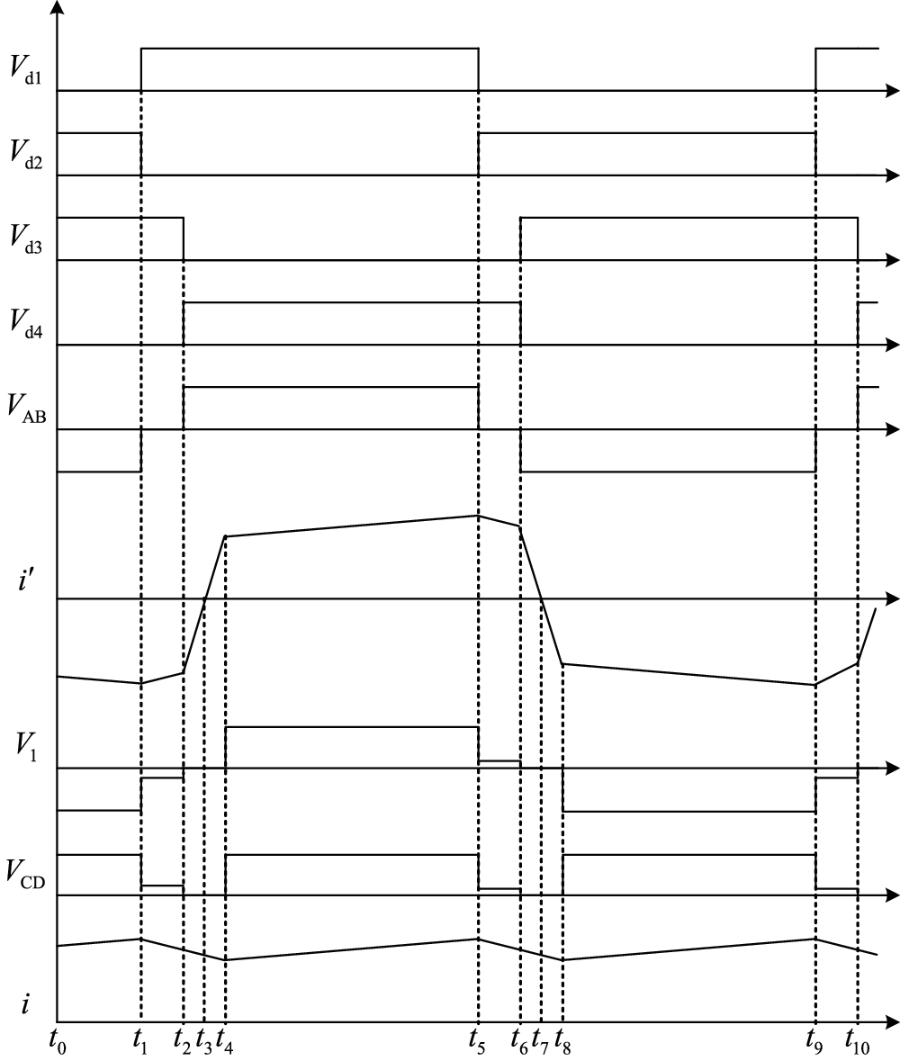
Figure 2: Waveforms of the phase-shifted full-bridge DC-DC converter during its operating process
Subinterval 1 [t1 − t2]: VT1 is turned on and VT2 is turned off at t1. Parasitic capacitance C1, C2, original side equivalent leakage inductance of the high frequency transformer Lk and the series equivalent inductance L produce resonance, causing C1 discharge, C2 charge. When C1 finishes discharging, the equivalent antiparallel diode VD1 begins to freewheel. At this stage, VT2 performs zero-voltage turn-off, and VT1 prepares for zero-voltage turn-on. In Subinterval 1, the equivalent circuit is shown in Fig. 3. VAB = 0, i′ < 0 and its absolute value decreases with the slope of
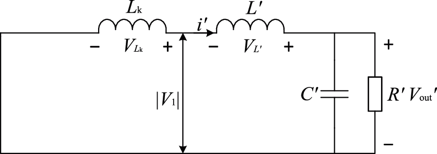
Figure 3: Equivalent circuit of the DC-DC converter in Subinterval 1
Subinterval 2 [t2 − t3]: VT4 is turned on and VT3 is turned off. C4 starts to discharge at t2. At this time, the parasitic capacitance C3 and C4 resonate with Lk. When C4 is discharged to 0, the antiparallel diode VD4 turns on. In Subinterval 2, the equivalent circuit is shown in Fig. 4. VAB = Vin, i′ < 0 and its absolute value decreases with the slope of Vin/Lk; the original side voltage of the transformer V1 = 0; the output voltage of the rectifier bridge VCD = 0, and the output current i of the DC-DC converter decreases with the slope of Vout/L.
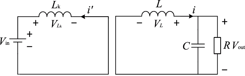
Figure 4: Equivalent circuit of the DC-DC converter in Subintervals 2 and 3
Subinterval 3 [t3 − t4]: At t3, the current in the input side of the transform becomes 0 and a positive current is established rapidly. The current in VD1 and VD4 are commutated to VT1 and VT4, and VT1 and VT4 zero voltage turns on. In t3 − t4, the equivalent circuit is the same as Subinterval 2, and the actual direction of the input current is opposite. In Subinterval 3, the equivalent circuit is shown in Fig. 2, which is similar to Subinterval 2.
Subinterval 4 [t4 − t5]: In Subinterval 4, the equivalent circuit is shown in Fig. 5,
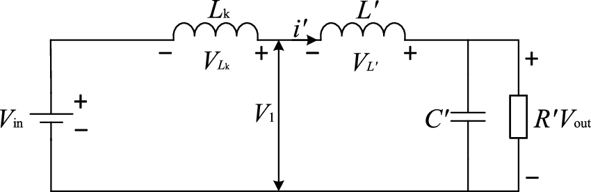
Figure 5: Equivalent circuit of the DC-DC converter in Subinterval 4
The latter four stages are similar to the previous four stages. It will not be repeated here. Note that not only the relationship and the waveform of each electric quantity in the steady-state state is obtained above, but also the zero-voltage switching can be realized in the phase-shifting full-bridge DC-DC converter.
2.2 DC-DC Converter Mathematical Model
To establish the mathematical model of the DC-DC converter, some assumptions are follows:
(1) All power electronics devices are ideal devices;
(2) The high-frequency transformer is an ideal transformer;
(3) The input voltage is constant and the capacitance is infinite;
(4) The load is the resistance load.
In order to realize the modulation of the DC-DC converter, it is necessary to divide bridge legs of the full-bridge converter into the leading bridge leg and the lagging bridge leg. The driving signals of VT1 and VT2 are ahead of that of VT4 and VT3, respectively. The bridge leg composed of VT1 and VT2 is called the leading bridge leg, while the bridge leg composed of VT4 and VT3 is called the lagging bridge leg.
The leading bridge leg is denoted as A bridge leg and the lagging bridge leg is denoted as B bridge leg.
The binary logical function Sk is defined as:
When using ideal power electronics devices, if SA = 0, SB = 0, then VAB = 0; if SA = 0, SB = 1, then VAB = −Vin; if SA = 1, SB = 0, then VAB = Vin; if SA = 1, SB = 1, then VAB = 0, so:
If the leakage inductance is small, it can be ignored. At this point, the output voltage of the secondary side:
When the voltage drop of the rectifier diode is ignored, the output voltage of the rectifier bridge is:
Considering the internal resistance r of the filter inductance, the instantaneous value of the output voltage of the DC-DC converter is vout, so the mathematical model described by the switching function is obtained:
where p is the differential operator. Making assumption:
Therefore, Eq. (5) can be simplified as:
This is the mathematical model of the DC-DC converter.
3 Traditional Control Algorithm of DC-DC Converter
The phase shift control modulation method is used in the DC-DC converter [31]. The pulse waveforms of the phase-shifting control modulation method are shown in the Fig. 6. The Vd1, Vd2, Vd3 and Vd4 are the driving voltage of VT1, VT2, VT3, VT4; VAB is the full bridge output voltage waveform;
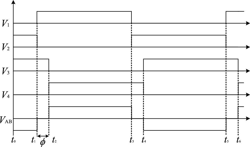
Figure 6: Waveforms of the phase-shift control modulation method
Set t1 − t5 as a period, so the average voltage output by the converter is:
So, the output voltage can be adjusted by adjusting the phase shift angle.
According to the mathematical model in Section 2.2, the average mathematical model can be obtained:
where, M can be gotten by
Firstly, considering the current loop, the current model equation is:
The PI regulator is used as the current regulator. The output of the current loop can be gotten by:
Secondly, the voltage loop model equation is:
The voltage loop also uses PI regulator, and the output is:
where KiP, KiI, KvP and KvL are the control parameters of the DC-DC converter. Therefore, the control structure of the DC-DC converter is shown in Fig. 7.
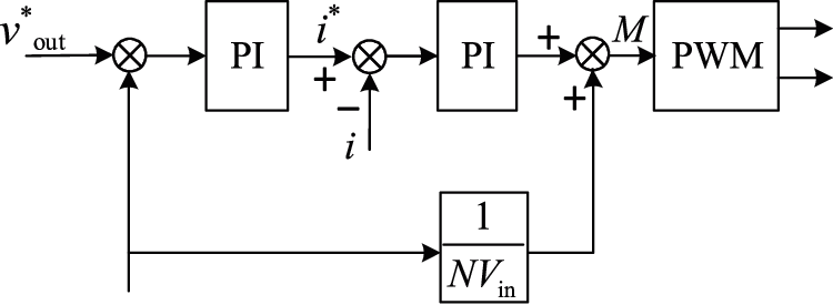
Figure 7: DC-DC converter control structure diagram
Firstly, the given voltage is compared with the voltage feedback, then the given current value is obtained through the PI regulator. Similarly, the given current is compared with the feedback current, and then the comparison result is calculated by the PI regulator. The output result is added with the voltage feed forward to obtain the M. M is used to get the PWM signal, which is used to control the full bridge of DC-DC converter. The output voltage can be controlled finally. The 1/NVin control branch is the voltage feed forward branch, which is used to increase the response speed of the control system.
The control block diagram of DC-DC converter is obtained as shown in Fig. 8.
The traditional PI control for the voltage regulation of the DC-DC converter of the PEMFC is basically feasible. The mathematical model is simple and the practical operation is easy to realize. However, PEMFC is a nonlinear and time-varying complex system and it is vulnerable to external interference in the working process. So, the traditional PI control cannot get the better effect. In order to achieve the better control effect, this paper proposes adaptive fuzzy PI control in the next section and compares it with the traditional PI control.
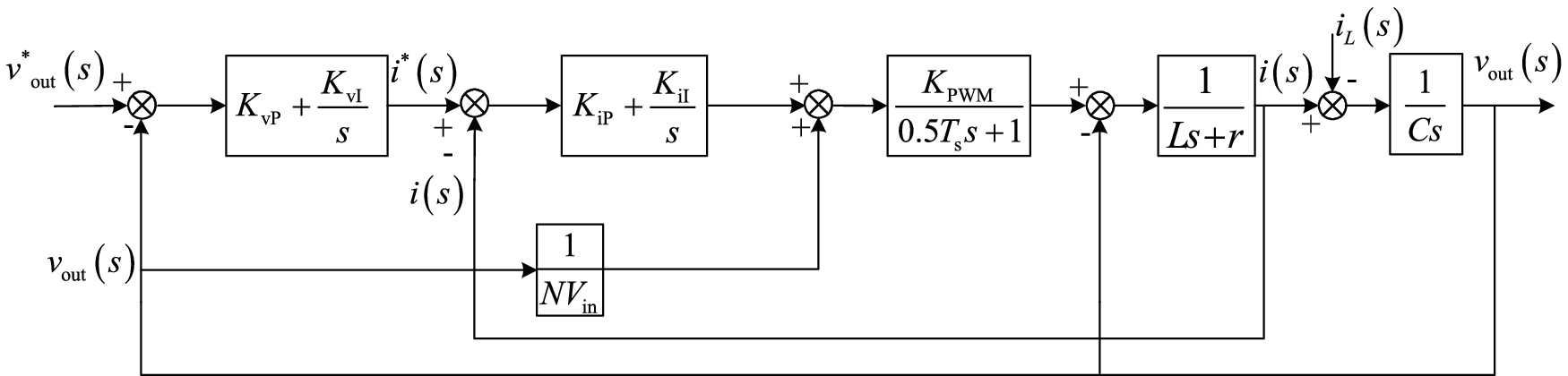
Figure 8: Dynamic structure diagram of the DC-DC converter based on the traditional PI controller
4 Design of Adaptive Double Closed Loop PI Controller
In the previous section, we have introduced the principle of DC-DC converter based on the traditional PI controller. In the actual experiment, the performance of the traditional PI is not ideal due to the particularity of the fuel cell. Therefore, we design an adaptive double closed-loop PI controller based on the traditional PI controller by analyzing the data characteristics.
Compared with the traditional control method, the controller in this paper adopts the design of the current and voltage double closed-loop. The PI controller parameters can be adjusted adaptively according to the different working states of the fuel cell, which makes the whole control system more targeted.
4.1 Analysis of Power Supply Starting Condition
In the start-up of the DC-DC converter of the fuel cell, the output voltage vout changes from zero, and the given target voltage value v*out is much larger than vout. To ensure the stability of the system, the PI regulator output of the voltage regulator will soon reach the threshold. At this time, the performance of the system voltage output is mainly determined by the current regulator.
In the adjustment process of the starting link, the ideal current i* reaches the maximum threshold i*max. The current regulation PI regulator can be viewed as a control for the actual output current i. In the fuel cell, the current i fluctuates greatly due to the work of the phase-shifting full-bridge DC-DC converter (as shown in Fig. 9). In order to control the rapid response of the output voltage, a fuzzy PI regulator is designed in this paper, and its system structure is shown in Fig. 10. The main parameters in the fuzzy PI control are KvP, KvI, KiP, KiI. KvP is the proportional coefficient of the voltage regulator and KvI is the integral coefficient of the voltage regulator. When KvP and KvI become larger, the response rate of the voltage will be fast but the stability will be poor. When KvP and KvI become smaller, the oscillation of the voltage will be smaller and the disturbance rejection will be enhanced. KiP is the proportional coefficient of the current regulator and KiI is the integral coefficient of the current regulator. When KiP and KiI become larger, the response rate of the current will be fast but the stability will be poor. When KiP and KiI become smaller, the oscillation of the current will be smaller and the ability of disturbance rejection will be enhanced.
The fuzzy PI controller takes the voltage error ev = v*out – vout as the input. According to the fuzzy rules, when the error is large, the voltage regulation PI regulator reaches the threshold value. Meanwhile, a larger control parameter KiP and KiI is given to increase the system speediness and make the output voltage quickly reach the ideal state. When the error ev decreases gradually and the voltage PI regulator drops below the maximum threshold, the fuzzy rules are set to reduce the control variables KiP and KiI of the current regulated PI regulator. The process of changing parameters can help to increase the stability of the system.
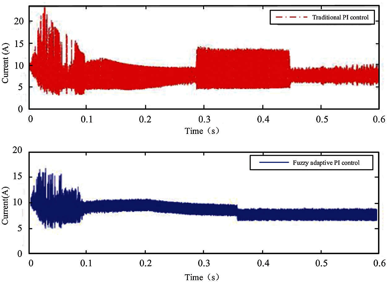
Figure 9: Actual output current i of the DC-DC converter
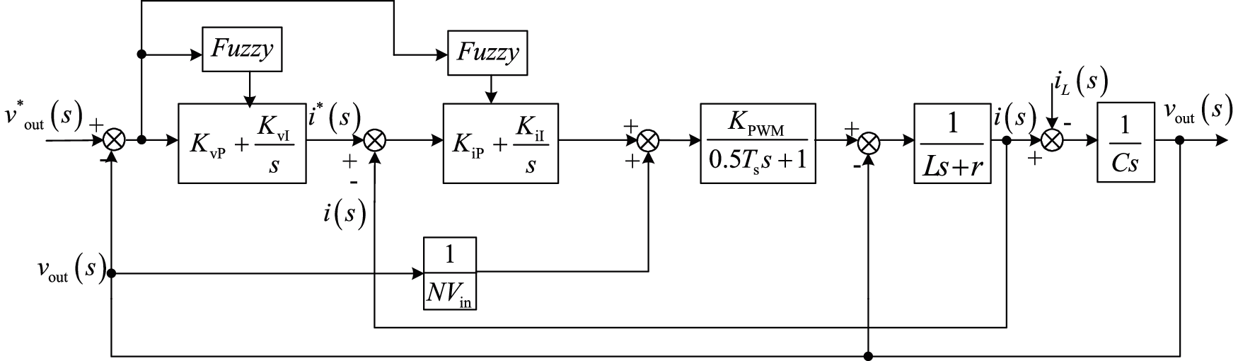
Figure 10: Dynamic structure diagram of the DC-DC converter based on the adaptive fuzzy PI controller
4.2 Analysis of the Load Condition
According to the introduction of the adaptive fuzzy PI current regulator in the previous section, the fuel cell can quickly and stably reach the set ideal voltage value. However, when the load decreases suddenly, the voltage increases suddenly, and the fall speed of the theoretical current i* is much faster than the change of actual current i. To reduce the overshoot of output voltage and improve the response speed, the voltage regulator should be improved.
In view of the working situation after decreasing the load, an adaptive fuzzy PI voltage regulator is proposed, which can autonomously adapt the control variables KvP and KvI of the voltage PI regulator and the current PI regulator by monitoring the change error of the ideal current of the load. The whole design process is similar to that of the fuzzy PI current regulator. The fuzzy PI controller takes the voltage error ev = v*out – vout as the input, and the output variables are voltage regulator parameters KvP and KvI. At run time, the control system completes the adaptive control of the PI controller through the result of fuzzy rules processing, table and operation.
5 Simulation Results and Analysis
To verify the control performance of the proposed algorithm, a full bridge converter was built in MATLAB/Simulink. Table 1 shows the parameters of the main circuit, and Fig. 11 shows the main circuit of the full-bridge converter.
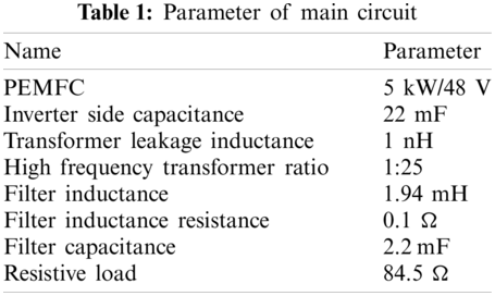
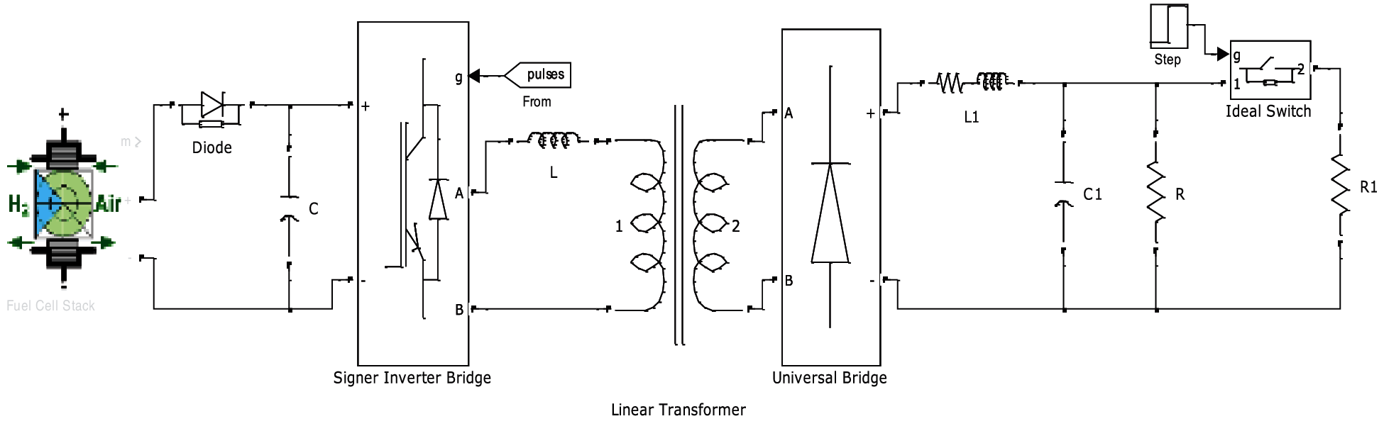
Figure 11: Main circuit of the full bridge converter
According to the performance requirements of the fuel cell DC-DC converter, the experimental conditions of the full load starting and the load reducing disturbance are set. In the experiment, the system starts at 0 s, the target voltage is 650 V, and the total load resistance is 84.5 Ω, which means the full load operation. At 1 s, the contactor is disconnected, and the total load resistance is 169 Ω, which means the half load operation. The experiment mainly tests the rapidity of the system when it starts at the full load and the anti-interference performance when the load is decreased.
It can be seen from Fig. 12 that when the fuel cell is working, its voltage fluctuation is larger than that of the fixed voltage source, and the maximum amplitude fluctuation is nearly 20%.
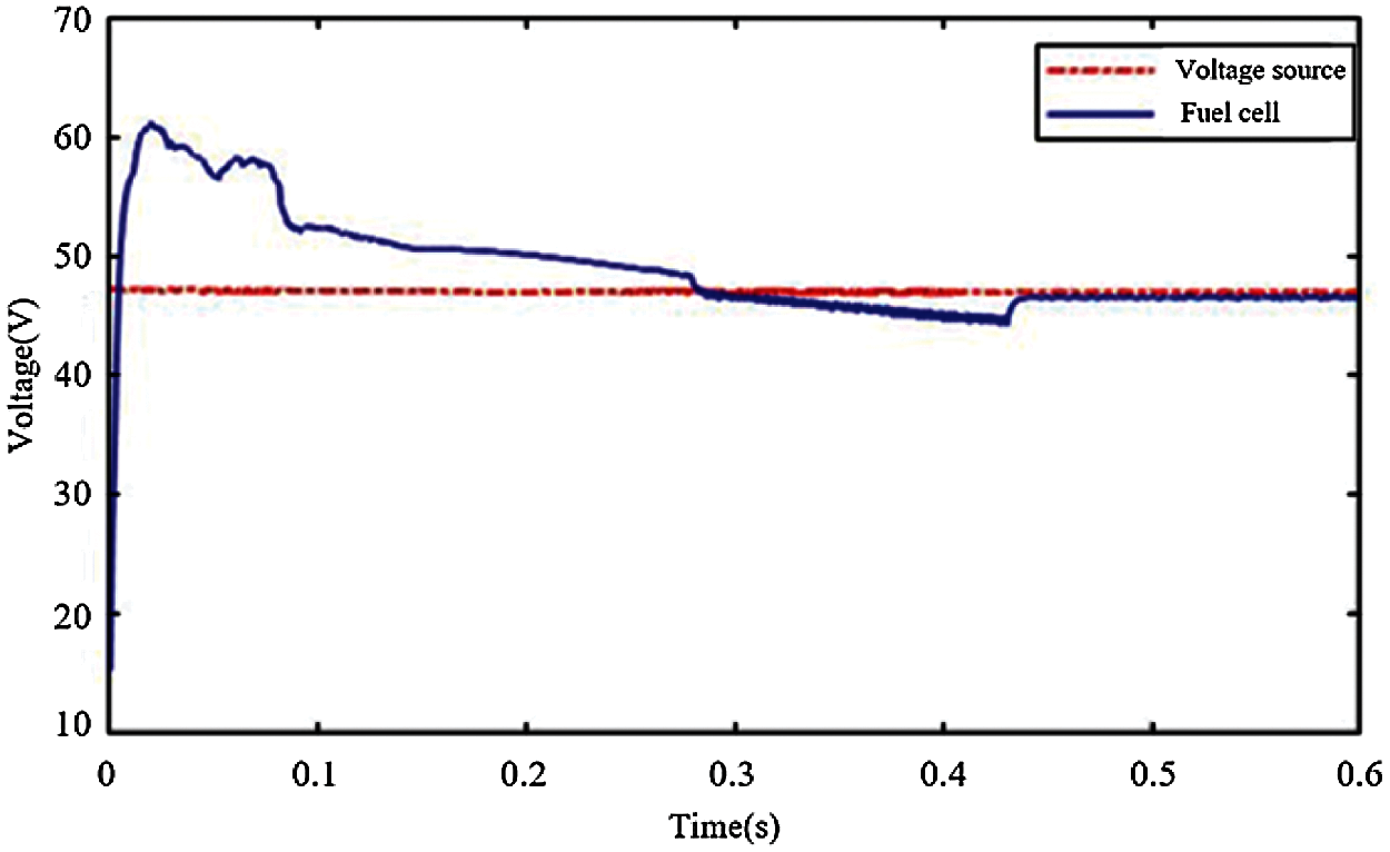
Figure 12: DC-DC converter input voltage variation under the action of the fixed voltage source and the fuel cell
The results in Fig. 13 show that the fluctuation of the fuel cell current will lead to the increase of output voltage regulation time of the DC-DC converter, and the traditional PI controller will lead to the decline of the fuel cell performance. Therefore, it is very necessary to propose a new controller for the fuel cell.
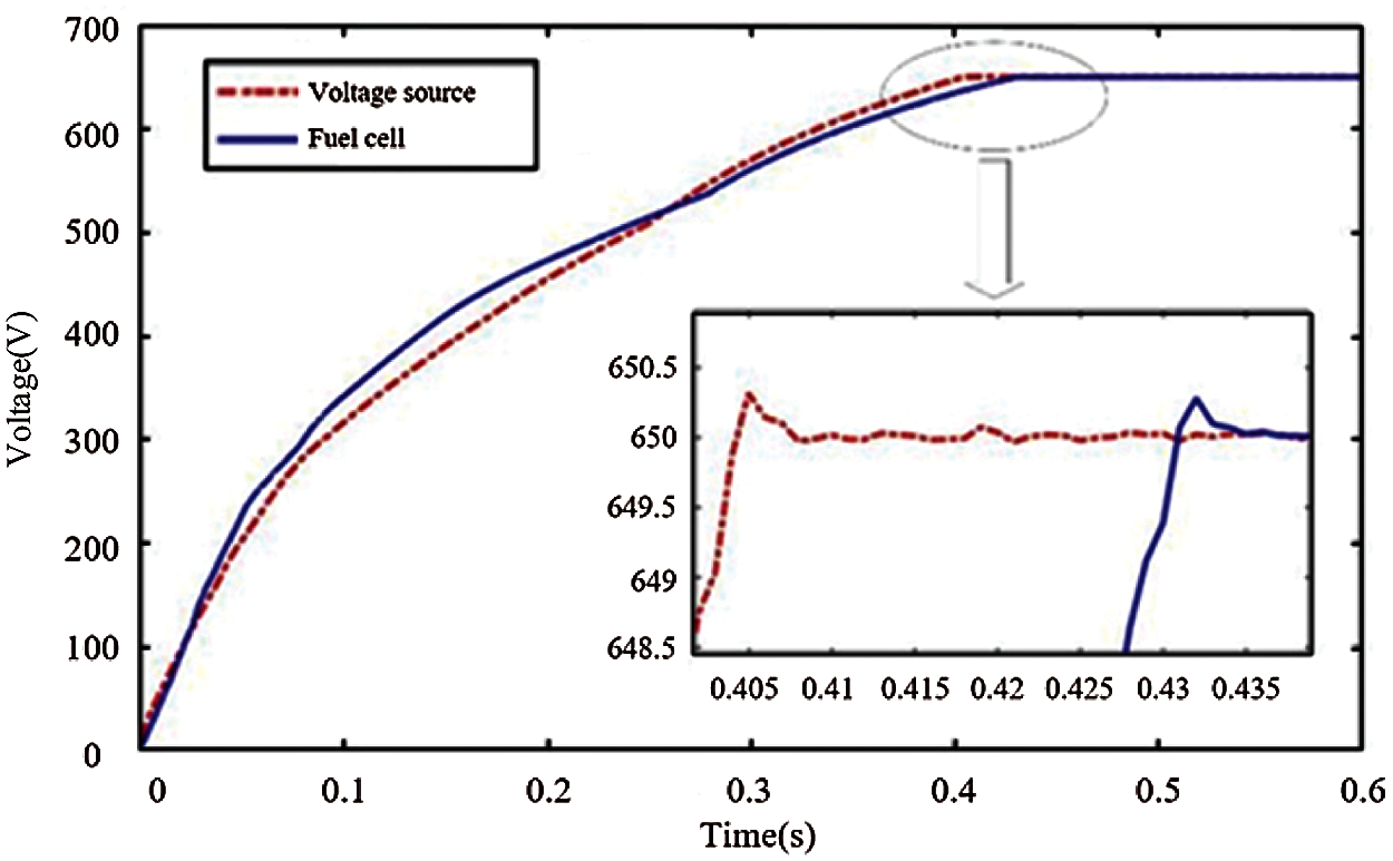
Figure 13: Voltage variation of output terminal of the DC-DC converter under traditional PI controller
The results in Fig. 14 show that the DC-DC converter can establish the stable output voltage quickly under the action of the fuzzy adaptive PI controller at full-load starting, and the voltage regulation time is 0.35 s, which is about 20% less than the 0.44 s of the traditional PI current regulator. According to the data details in the figure, the voltage overshoot and steady-state error of the new algorithm are also smaller than that of the traditional PI controller, and the range of the steady-state error is about ±0.05 V, which meets the requirements.
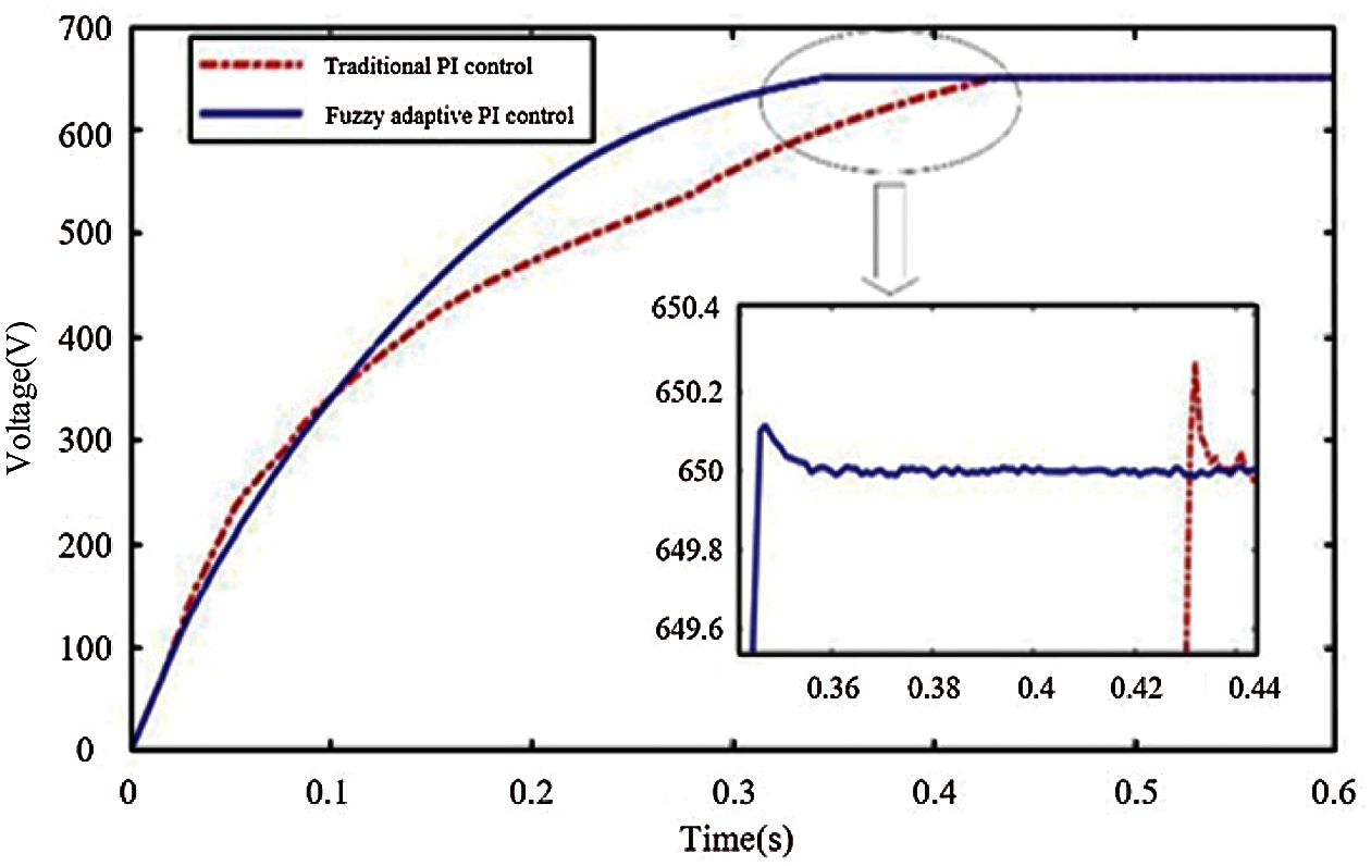
Figure 14: Voltage variation at the DC-DC output terminal of the fuel cell converter during startup
Compared with the traditional PI voltage regulator, as shown in Fig. 15, the new algorithm can greatly reduce the overshoot, and its adjustment time is 0.014 s, which is very fast and meets the requirements. The waveform with the red dotted line in the Fig. 15 is the voltage variation at the DC-DC output terminal when the traditional PI control is used and the load decreases. The waveform with the blue line is the voltage variation when the fuzzy adaptive PI control is used and the load decreases.
In order to better display its disturbance rejection performance, the voltage variation when the load increases is shown in Fig. 16. The test condition is that the load step from the half load to the full load at 1 s. The waveform with the red dotted line is the voltage variation at the DC-DC output terminal when the traditional PI control is used and the load increases. The waveform with the blue line is the voltage variation when the fuzzy adaptive PI control is used and the load increases.
Fig. 17 shows the voltage waveforms of the fuel cell when the traditional PI control and the fuzzy PI control are used respectively. From the figure, the fuel cell voltage can reach the steady value more quickly in the boot process when the fuzzy PI control is used. In addition, note that the adaptive fuzzy PI controller can effectively reduce the fluctuation of the output voltage of the fuel cell converter from the data in the figure, which is conducive to the normal operation of the fuel cell.
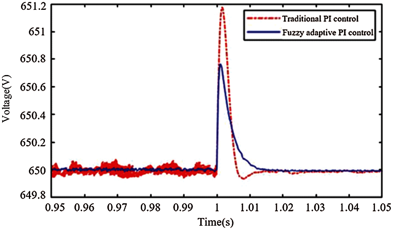
Figure 15: Voltage variation at the DC-DC output terminal of the fuel cell converter when the load decreases
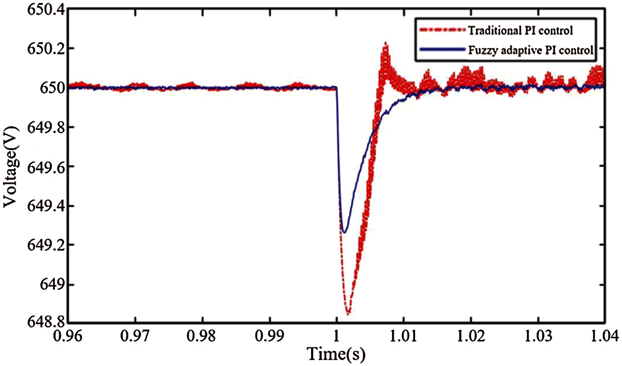
Figure 16: Voltage variation at the DC-DC output terminal of the fuel cell converter when the load increases
In order to test the anti-noise performance, the comparison before and after considering the measurement noise is added, which is shown in Fig. 18. In the test, the signal-to-noise ratio for both voltage and current signals is set at about 5%, which is the serious situation in practice. The result shows no significant difference in both cases, which means the controller has strong anti-noise performance.
Figs. 19 and 20 show the switching waveforms of the full-bridge within 0 to 0.25 s when the traditional PI control and the adaptive fuzzy PI control are adopted (the waveforms are the voltage of the point A relative to the point B in Fig. 1). Note that the output voltage of the full-bridge is higher at the start-up stage of the converter when the adaptive fuzzy PI control is adopted. At the initial stage, the input error of the PI regulator is large. According to the fuzzy control rules, the proportional coefficient and the integral coefficient of the PI regulator become larger, and the full-bridge output voltage becomes higher. When approaching the steady state, the proportional and integral coefficients of the PI regulator will be adjusted for several times as the input error of the PI regulator decreases, so the multi-step waveforms in the dotted frame in Fig. 20 is presented.
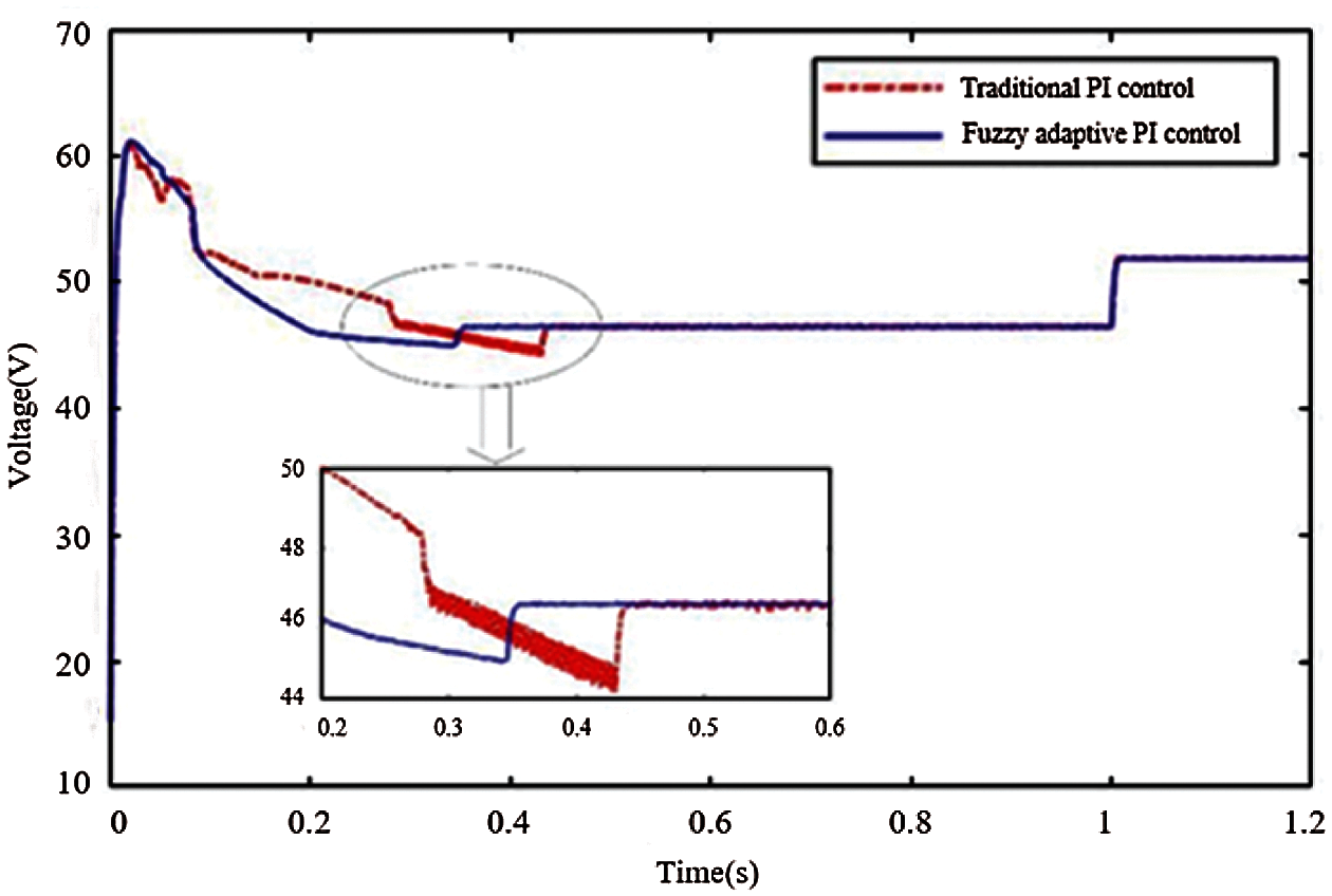
Figure 17: Change of the fuel cell output voltage during simulation experiment
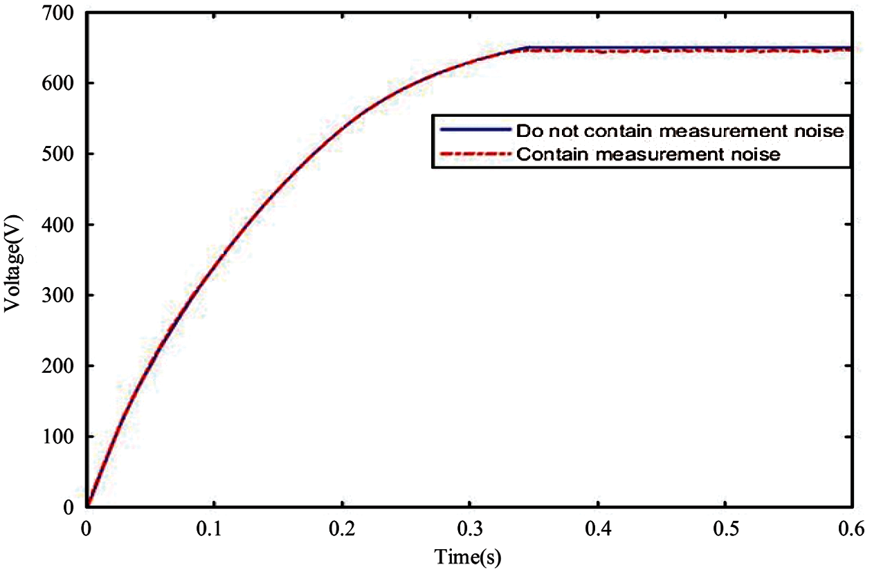
Figure 18: The comparison before and after considering the measurement noise
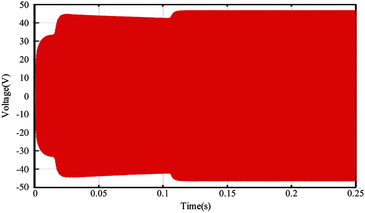
Figure 19: Switching waveform of the full-bridge within 0 to 0.25 s when the traditional PI control is adopted
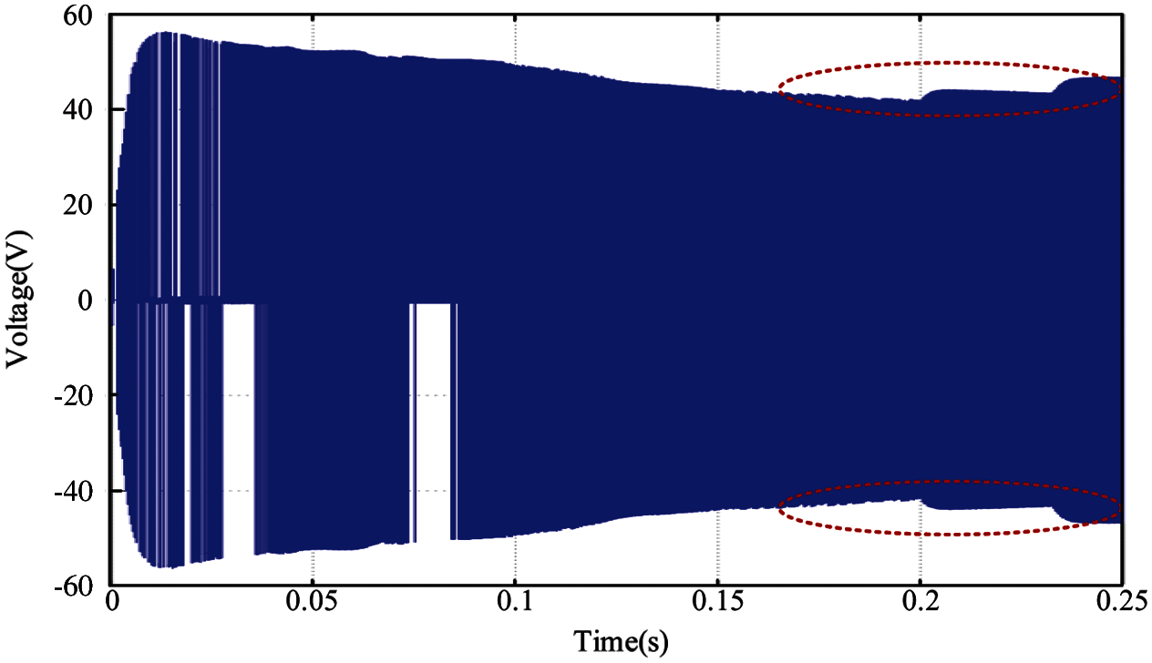
Figure 20: Switching waveform of the full-bridge within 0 to 0.25 s when the adaptive fuzzy PI control is adopted
In this paper, a double closed-loop adaptive fuzzy PI controller is proposed to dynamically adjust PI parameters. The new algorithm can complete the intelligent control of the phase-shifting full-bridge DC-DC converter of the fuel cell under different task states. The simulation results in MATLAB/Simulink show that the algorithm proposed in this paper has a better control effect. Because of the particularity of the fuel cell, the traditional PI control can not give full play to the excellent performance of the fuel cell DC-DC converter. The proposed fuzzy control can not only effectively control the output voltage of the DC-DC converter to be the set value with faster speed and low overshoot, but also enhance its disturbance rejection performance and reduce the output current ripple. In addition, compared with the traditional PI control, it can reduce the adjustment time and the fluctuation of the fuel cell output voltage when the system starts up.
Funding Statement: This work was supported in part by the Natural Science Foundation of Jiangsu Province under Grant BK20200969 (L. Z., URL: http://std.jiangsu.gov.cn/), and in part by the Natural Science Foundation for Universities of Jiangsu Province under Grant 20KJB520008 (Y. Y., URL: http://jyt.jiangsu.gov.cn/), and in part by the Nantong Science and Technology Plan Project under Grant JC2020148 (Y. Y., URL: http://kjj.nantong.gov.cn/), JC2020151 (Y. C., URL: http://kjj.nantong.gov.cn/), JC2019095 (L. R., URL: http://kjj.nantong.gov.cn/).
Conflicts of Interest: The authors declare that they have no conflicts of interest to report regarding the present study.
1. Singh, S. N., Singh, B., Ostergaard, J. (2009). Renewable energy generation in India: Present scenario and future prospects. IEEE Power & Energy Society General Meeting, pp. 1–8. Calgary, AB, Canada. DOI 10.1109/PES.2009.5275448. [Google Scholar] [CrossRef]
2. Elavarasan, R. M., Shafiullah, G. M. (2020). A comprehensive review on renewable energy development, challenges, and policies of leading Indian states with an international perspective. IEEE Access, 8, 74432–74457. DOI 10.1109/ACCESS.2020.2988011. [Google Scholar] [CrossRef]
3. Mustpa, S. I., Hashim, A. H. (2010). Issues and challenges of renewable energy development: A Malaysian experience. Proceedings of the International Conference on Energy and Sustainable Development: Issues and Strategies, pp. 1–6. Chiang Mai, Thailand. [Google Scholar]
4. Kishore, G. I., Premkumar, M., Tripathi, R. K., Nalamati, C. S. (2021). A novel single switch high gain DC-DC converter topology for renewable energy systems. Energy Engineering, 118(2), 199–209. DOI 10.32604/EE.2021.014079. [Google Scholar] [CrossRef]
5. Lindahl, P. A., Shaw, S. R., Leeb, S. B. (2018). Fuel cell stack emulation for cell and hardware-in-the-loop testing. IEEE Transactions on Instrumentation and Measurement, 67(9), 2143–2152. DOI 10.1109/TIM.2018.2814070. [Google Scholar] [CrossRef]
6. Tian, Y., Zou, Q., Lin, Z. (2020). Hydrogen leakage diagnosis for proton exchange membrane fuel cell systems: Methods and suggestions on its application in fuel cell vehicles. IEEE Access, 8, 224895–224910. DOI 10.1109/ACCESS.2020.3044362. [Google Scholar] [CrossRef]
7. Qi, Z., Tang, J., Pei, J., Shan, L. (2020). Fractional controller design of a DC-DC converter for PEMFC. IEEE Access, 8, 120134–120144. DOI 10.1109/ACCESS.2020.3005439. [Google Scholar] [CrossRef]
8. Han, Y., Li, Q., Wang, T., Chen, W., Ma, L. (2018). Multisource coordination energy management strategy based on SOC consensus for a PEMFC–battery–supercapacitor hybrid tramway. IEEE Transactions on Vehicular Technology, 67(1), 296–305. DOI 10.1109/TVT.2017.2747135. [Google Scholar] [CrossRef]
9. Wang, T., Li, Q., Wang, X., Chen, W., Breaz, E. et al. (2020). A power allocation method for multistack PEMFC system considering fuel cell performance consistency. IEEE Transactions on Industry Applications, 56(5), 5340–5351. DOI 10.1109/TIA.2020.3001254. [Google Scholar] [CrossRef]
10. Zhong, C., Li, S. (2016). Control strategies for the air supply system in PEMFC. 35th Chinese Control Conference, pp. 4336–4341. Chengdu, China. [Google Scholar]
11. Tang, X., Wang, C., Mao, J., Liu, Z. (2020). Adaptive fuzzy PID for proton exchange membrane fuel cell oxygen excess ratio control. Chinese Control and Decision Conference, pp. 193–197. Hefei, China. [Google Scholar]
12. Mat, Z. B. A., Kar, M. Y. B., Talik, N. A. B. (2017). Proton exchange membrane (PEM) and solid oxide (SOFC) fuel cell based vehicles—A review. 2nd IEEE International Conference on Intelligent Transportation Engineering, pp. 123–126. Singapore. [Google Scholar]
13. Tusher, M. M. I., Hoque, M. E., Uddin, M. J., Mainuddin, A., Talukder, M. M. U. (2019). A comparative study of a PEMFC, battery, super-capacitor based energy source owing to hybrid vehicle. International Conference on Sustainable Technologies for Industry 4.0, pp. 1–4. Dhaka, Bangladesh. [Google Scholar]
14. Gorji, S. A., Sahebi, H., Ektesabi, G. M., Rad, A. B. (2019). Topologies and control schemes of bidirectional DC-DC power converters: An overview. IEEE Access, 7, 117997–118019. DOI 10.1109/ACCESS.2019.2937239. [Google Scholar] [CrossRef]
15. Mangu, B., Akshatha, S., Suryanarayana, D., Fernandes, B. G. (2016). Grid-connected PV-wind-battery-based multi-input transformer-coupled bidirectional DC-DC converter for household applications. IEEE Journal of Emerging and Selected Topics in Power Electronics, 4(3), 1086–1095. DOI 10.1109/JESTPE.2016.2544789. [Google Scholar] [CrossRef]
16. Forouzesh, M., Siwakoti, Y. P., Gorji, S. A., Blaabjerg, F., Lehman, B. (2017). Step-up DC-DC converters: A comprehensive review of voltage-boosting techniques, topologies, and applications. IEEE Transactions on Power Electronics, 32(12), 9143–9178. DOI 10.1109/TPEL.2017.2652318. [Google Scholar] [CrossRef]
17. Pesce, C., Blasco, R., Riedemann, J., Andrade, I., Peña, R. (2016). A DC-DC converter based on modified flyback converter topology. IEEE Latin America Transactions, 14(9), 3949–3956. DOI 10.1109/TLA.2016.7785917. [Google Scholar] [CrossRef]
18. Lee, H., Yun, J. (2019). High-efficiency bidirectional buck-boost converter for photovoltaic and energy storage systems in a smart grid. IEEE Transactions on Power Electronics, 34(5), 4316–4328. DOI 10.1109/TPEL.2018.2860059. [Google Scholar] [CrossRef]
19. Huang, X., Lee, F. C., Li, Q., Du, W. (2016). High-frequency high-efficiency GaN-based interleaved CRM bidirectional buck/boost converter with inverse coupled inductor. IEEE Transactions on Power Electronics, 31(6), 4343–4352. DOI 10.1109/TPEL.2015.2476482. [Google Scholar] [CrossRef]
20. Wang, Y., Xue, L., Wang, C., Wang, P., Li, W. (2016). Interleaved high-conversion-ratio bidirectional DC–DC converter for distributed energy-storage systems-circuit generation, analysis, and design. IEEE Transactions on Power Electronics, 31(8), 5547–5561. DOI 10.1109/TPEL.2015.2496274. [Google Scholar] [CrossRef]
21. Ibrahim, O., Yahaya, N. Z., Saad, N., Ahmed, K. Y. (2017). Development of observer state output feedback for phase-shifted full bridge DC-DC converter control. IEEE Access, 5, 18143–18154. DOI 10.1109/ACCESS.2017.2745417. [Google Scholar] [CrossRef]
22. Su, M., Dong, H., Liu, K., Zou, W. (2020). A subsynchronous oscillation suppression method based on self-adaptive auto disturbance rejection proportional integral control of voltage source converter based multi-terminal direct current system with doubly-fed induction generator-based wind farm access. Energy Engineering, 117(6), 439–452. DOI 10.32604/EE.2020.011805. [Google Scholar] [CrossRef]
23. Cao, P., Fan, H., Cai, Z. (2021). Adaptive fractional-order PID control for VSC-HVDC systems via cooperative beetle antennae search with offshore wind integration. Energy Engineering, 118(2), 265–284. DOI 10.32604/EE.2021.014513. [Google Scholar] [CrossRef]
24. Guo, Z., Sha, D., Liao, X., Luo, J. (2014). Input-series-output-parallel phase-shift full-bridge derived DC-DC converters with auxiliary LC networks to achieve wide zero-voltage switching range. IEEE Transactions on Power Electronics, 10(29), 5081–5086. DOI 10.1109/TPEL.2014.2309342. [Google Scholar] [CrossRef]
25. Liu, Z., Wang, F., Zhang, Y., Chen, X., Chen, C. L. P. (2015). Adaptive tracking control for a class of nonlinear systems with a fuzzy dead-zone input. IEEE Transactions on Fuzzy Systems, 23(1), 193–204. DOI 10.1109/TFUZZ.2014.2310491. [Google Scholar] [CrossRef]
26. Biricik, S., Komurcugil, H. (2018). Proportional-integral and proportional-resonant based control strategy for PUC inverters. 44th Annual Conference of the IEEE Industrial Electronics Society, pp. 3369–3373. Washington DC. [Google Scholar]
27. Kim, I. H., Son, Y. I. (2017). Regulation of a DC/DC boost converter under parametric uncertainty and input voltage variation using nested reduced-order PI observers. IEEE Transactions on Industrial Electronics, 64(1), 552–562. DOI 10.1109/TIE.2016.2606586. [Google Scholar] [CrossRef]
28. Lu, Y. (2018). Adaptive-fuzzy control compensation design for direct adaptive fuzzy control. IEEE Transactions on Fuzzy Systems, 26(6), 3222–3231. DOI 10.1109/TFUZZ.2018.2815552. [Google Scholar] [CrossRef]
29. Wang, A. L., Qiu, L. J., Feng, G. (2019). Event-triggered robust adaptive fuzzy control for a class of nonlinear systems. IEEE Transactions on Fuzzy Systems, 27(8), 1648–1658. DOI 10.1109/TFUZZ.2018.2886158. [Google Scholar] [CrossRef]
30. Chen, B., Liu, X., Lin, C. (2018). Observer and adaptive fuzzy control design for nonlinear strict-feedback systems with unknown virtual control coefficients. IEEE Transactions on Fuzzy Systems, 26(3), 1732–1743. DOI 10.1109/TFUZZ.2017.2750619. [Google Scholar] [CrossRef]
31. Sagar Bhaskar, M., Ramachandaramurthy, V. K., Padmanaban, S. F., Blaabjerg, D. M. (2020). Survey of DC-DC non-isolated topologies for unidirectional power flow in fuel cell vehicles. IEEE Access, 8, 178130–178166. DOI 10.1109/ACCESS.2020.3027041. [Google Scholar] [CrossRef]
 | This work is licensed under a Creative Commons Attribution 4.0 International License, which permits unrestricted use, distribution, and reproduction in any medium, provided the original work is properly cited. |