| Energy Engineering |
DOI: 10.32604/EE.2022.018145
ARTICLE
Pressure-Induced Instability Characteristics of a Transient Flow and Energy Distribution through a Loosely Bent Square Duct
1Department of Mathematics, Jagannath University, Dhaka, 1100, Bangladesh
2School of Mechanical and Mechatronic Engineering, University of Technology Sydney, New South Wales, Australia
*Corresponding Author: Suvash Chandra Saha. Email: Suvash.Saha@uts.edu.au
Received: 02 July 2021; Accepted: 17 August 2021
Abstract: Due to widespread applications of the bent ducts in engineering fields such as in chemical, mechanical, bio-mechanical and bio-medical engineering, scientists have paid considerable attention to invent new characteristics of fluid flow in a bent duct (BD). In the ongoing study, a spectral-based numerical technique is applied to explore flow characteristics and energy distribution through a loosely bent square duct (BSD) of small curvature. Flow is accelerated due to combined action of the non-dimensional parameters; the Grashof number Gr (=1000), the curvature
Keywords: Square-shaped duct; curvature; secondary flow; energy distribution; chaos
Because of tremendous applications of the bent ducts (BD) in physical and natural sciences, bio-mechanical and bio-medical engineering, many highly ambitious researchers have given substantial attention in studying the flow and HT through a BD. The flow pattern inside the aorta and the bifurcation airways of the lung are intricate due to the complex curvature of the aorta and lung airways. The blood flow or the fluid flow inside the aorta or the bent channel respectively creates SFs causing the centrifugal force, and this SF along with the direction of the axial flow act at the right angle to the main flow direction. The curvature of the aorta and the lung airways shows different physically interesting flow characteristics for the pressure-driven flow. A lot of practical applications like fluid transportation, turbo machinery, gas turbines, heat exchangers, refrigeration, air conditioning system, ventilators, combustion engines, chemical reactors, centrifugal pumps etc., may be mentioned, which attracts the researchers to do advanced research in this fascinating field.
There is a wide-ranging study on fluid flow through a BD that has been continued for several decades. Due to the centrifugal force and tangential stress at the concave wall, acting towards the curvature of the channel center, supplementary secondary vortices appeared which is located near the concave wall, known as the Dean vortices. Dean [1] was the pioneer author who derived the mathematical model first and investigated the viscous incompressible fluid and discovered a pair of counter-rotating vortices appearing in a bent pipe. The bifurcation structure belonging to a combined flow bifurcation consists of several SSs, which are generally influenced by the Centrifugal force (caused due to channel curvature). Several influential investigations for various geometry of the BD were performed by Rudolf et al. [2], Norouzi et al. [3], Yanase et al. [4] for circular cross-section; Nandakumar et al. [5] for semi-circular cross-section; Kao [6] for an oval cross-section; Ligrani et al. [7], Yanase et al. [8], Finlay et al. [9] for a rectangular cross-section.
It has been established that the flow through a stationary bent duct with a temperature difference between the walls, two forces namely centrifugal force and heating-induced buoyancy forces act on the fluid that creates secondary flow. And since the secondary flow enhances heat and mass transfer, knowledge of the magnitude of these effects in different ranges of operating parameters is important in designing the mechanical devices. A comprehensive study of the bifurcation diagram of the fluid through a BSD was performed to investigate the combined solution structure [10]. An extensive simulation of the branching shape of the flow in a BRD was conducted first and detailed by Daskopoulos et al. [11]. Mondal [12] has investigated fluid flow in a BSD and BRD. A detailed study on such system using a spectral method on fluid flow bifurcation structure and stability of 2D flow is available in literature performed by Mondal et al. [13], who showed a close bonding to the transient behavior with the bifurcation diagram. Mondal et al. [14] also studied the bifurcation diagram, stability, and flow state of the flow in a BRD. To obtain reliable and meaningful characteristics and to get a better fundamental understanding of swirling flow and its thermal properties, an advanced numerical simulation model based on 3D vortex structures is used by Watanabe et al. [15]. They have described bifurcation phenomena and stability of the solutions in an SD for both two-and three-dimensional analysis. Chen et al. [16] performed a bifurcation study of the flow passing in a bent tube with increasing Dn and aspect ratio (Ar), where they observed two types of bifurcations depending on the range of Ar. Recently, Hasan et al. [17,18] applied a spectral-based numerical technique to investigate the critical points considering stationary and non-stationary BSD flow. In continuation of this study, very recently, Chanda et al. [19] investigated effects of curvature ratio on fluid flow and thermal distribution in a rotating BRD of aspect ratio 3 maintaining a temperature difference between the horizontal walls using the method that was used by Hasan et al. [20]. They studied flow scenarios over a wide range of the curvature (0.001 ≤ δ ≤ 0.5) for both co-and counter-rotation of the system. They obtained five branches of SS composed of 2- to 11-pair vortices. Effects of curvature on secondary vortices were also obtained and displayed in the bar diagrams. However, most of the previous studies have been performed to explore flow characteristics and temperature distribution through a bent square or rectangular-shaped ducts with medium or strong curvature that are differentially heated. The present work is relatively a comprehensive study on bifurcation structure as well as flow transition and energy distribution through a bent square duct with small curvature considering the bottom and outer walls heated while cooling the other two.
To obtain reliable and meaningful data as well as to get a better fundamental understanding of the oscillating behavior of the unsteady flow in a confined geometry, time-history analysis in a BRD was performed first by Yanase et al. [8]. Several works have been conducted for the last three decades about oscillating behavior in a confined geometry. Chandratilleke et al. [21] performed a numerical approach to elucidate the flow properties through the variable geometries duct for different aspect ratios heated the outer surface. Wang et al. [22] studied numerically and empirically the periodic fluctuation for an incompressible fluid in a BSD, and the comparison shows excellent agreement with both the results. Mondal et al. [23] conducted a numerical manner to analyze the flow transition in bent duct (BD). They investigated the impacts of Dn and Gr numbers on the SF pattern. Nowruzi et al. [24] applied the Homotopic perturbation method to investigate hydrodynamic instability in BD of small aspect ratio for several curvatures. However, their study was unable to focus on the influence of the parameters in the flow transition and velocity profiles. Islam et al. [25] deliberated the influence of the Dean number over a wide range of Tr on transition in a rotating CRD flow. Hasan et al. [18] reflected the numerical investigation of UF through a BSD, and the relationship was established between the stability of SS and US. Chanda et al. [26] conducted a numerical investigation through a BRD for both co-and counter-rotation cases. Very recently, Dolon et al. [27] developed a computational model on curved rectangular duct flow and investigated the combined effects of centrifugal and heating-induced buoyancy instability of the flow. They built up a relationship between the flow velocity and isotherms. Impacts of Dean vortex on overall heat transfer were also shown. However, studies on strong centrifugal instability received less attention before, while the transient solution with coupled impacts on buoyancy-influenced centrifugal unsteadiness through a stationary BSD is not considered though it has an extensive application in engineering processes; in this paper, efforts are directed to reduce this gap.
An essential phenomenon for curved-channel flow is the calculation of HT in a BD because of numerous engineering and industrial applications such as aeronautical, petroleum, mechanical and chemical engineering, metallic and plastic industry, etc. The mentionable applications of flows in the various curved duct (CD) are to promote HT in the fluid causing Dean vortices. Wang et al. [22] conducted a numerical analysis to explain the properties of swirling flow in a CD of aspect ratios 1 to 8 heating from the outer surface. Riyi et al. [28] performed the numerical simulations and experimental studies of the HT in an eccentric annular with maintaining temperature differences individually. Mondal et al. [13] studied the oscillating behavior of the thermal flow in a BSD numerically. The authors investigated the SF structure and the effects of HT performance. In the succeeding paper, Mondal et al. [29] investigated the regular and irregular oscillation with identifying the symmetry and without symmetry condition in flow behaviors, respectively. A numerical procedure, known as FDM, is used by Zhang et al. [30] to investigate the time-dependent CHT and mixing between two different geometries. Hasan et al. [31] performed numerical simulation with CHT through a rotating BSD for various curvatures. They discussed the steady and unsteady solutions with linear stability and found that SF enhances CHT significantly, and the chaotic flow, which occurs at large Dn’s, enhances HT more efficiently than the other US. Recently, Zhao et al. [32] illustrated the influence of friction factor and Nusselt number in terms of time instead of curvature ratios and large Reynolds numbers. Very recently, Chanda et al. [26] discussed the CHT for rotating BRD flow, and they obtained the nearly same result as obtained by Hasan et al. [33]. Very recently, Chanda et al. [34] applied spectral method to investigate heat-flux effect on fluid flow and energy distribution in a BRD. They obtained four SS comprising with 2- to 12-vortex solutions. Effects of curvature on secondary vortices were also obtained and displayed in the bar diagrams. All of these studies admittedly illustrate the flow pattern and heat transfer characteristics in bent square duct for moderate or large curvature, where time-dependent flow features in the presence of centrifugal and buoyancy forces with pressure-induced instability characteristics in a BSD with small curvature are not considered greatly though it has ample engineering applications e.g., plastic industry, metallic industry, gas turbines etc. Considering this issue in mind, an objective of this paper is to find complex structure of the transient flow feature and vortex formation of SF for fully developed 2D flow through a BSD with combined effects of free and forced convection on heat transfer.
The key intention of the current study is to examine the perplexing flow feature and energy distribution in a bent square-shaped duct by finding steady solutions and calculating non-linear behavior of the flow by time-evolution computation. The study articulates and verifies an advanced approach for computational scheme to well identify hydrodynamic variability in a BSD reflected by the generation of Dean vortices. The main purpose of this study is, therefore, to pursuit solution formation of SSs and explores transient behavior with heat-flux properties of secondary vortices (SV) on CHT.
2 Flow Model and Mathematical Formulation
The BSD, whose geometrical parameter of duct height (=width) is 2d, the radius of curvature
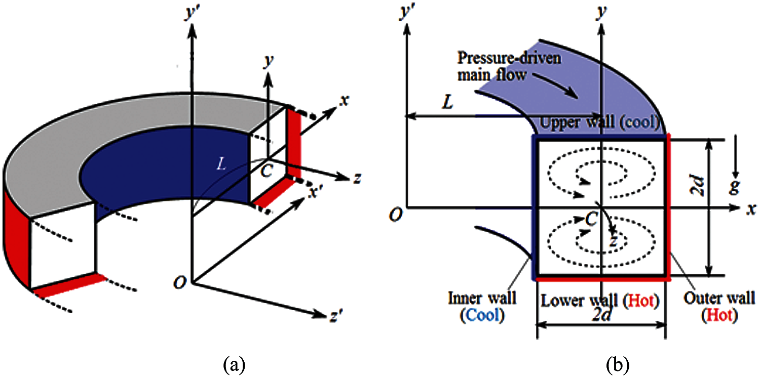
Figure 1: (a) Coordinate system (b) Cross-sectional view
Then, the advancement of transient flow and HT inside a BSD is governed by the following dimensional conservation of mass, momentum, and energy equation can be expressed as:
Conservation of mass equation:
Momentum equations:
Energy equation:
where,
The stream function
Considering the flow as invariant in the
and,
The non-dimensional parameters that characterize the flow and appear in Eqs. (7)–(9) are the Dean number,
The no-slip boundary condition for
\def\theequation{10\alph{equation}} \setcounter{equation}{0}
3.1 Method of Numerical Design
Since the method is numerically based, we have used the Spectral method as a numerical technique to solve the Eqs. (7)–(9). This is one of the best methods for solving the Momentum equation as well as energy equations (see Gottlieb et al. [35] for details). By this method, the variables are expanded in a series of functions consisting of Chebyshev polynomials. The expansion functions
where,
Here, the collocation points
where
which is solved simultaneously with Eq. (17) by using the Newton-Raphson iteration method with path continuation technique. An initial guess at a point
The convergence is assured by taking suitably small
Finally, in order to compute the time-dependent solution, the Crank-Nicolson and Adams–Bashforth methods along with the function expansion (13) and the collocation methods, are applied to Eqs. (7)–(9). A detailed description of the method is available in Mondal et al. [13].
3.2 Hydrodynamic Resistance Coefficient
The resistance coefficient
where,
The value
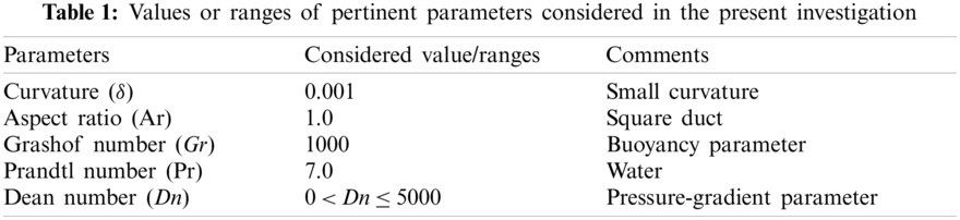
A detailed investigation has been carried out and discussed the branching structure, consisting of the SSs and unsteady solutions. Pertinent parameters are considered as shown in Table 1.
In order to find out the structure of SSs using the parameters as presented in Table 1, the result is presented in Fig. 2a. We noticed from Fig. 2a that six asymmetric branches of SSs are available, which are named as the 1st, 2nd, 3rd, 4th, 5th, and the 6th steady branch (br). Assorted colors and line patterns have been used to distinguish the obtained branches. Fig. 2b represents the amplification of Fig. 2a for visualizing the perplexing branch structure more pronouncedly as well as to categorize the SSs from each other. It is observed from Fig. 2a that only the 1st branch covers the entire region of Dn
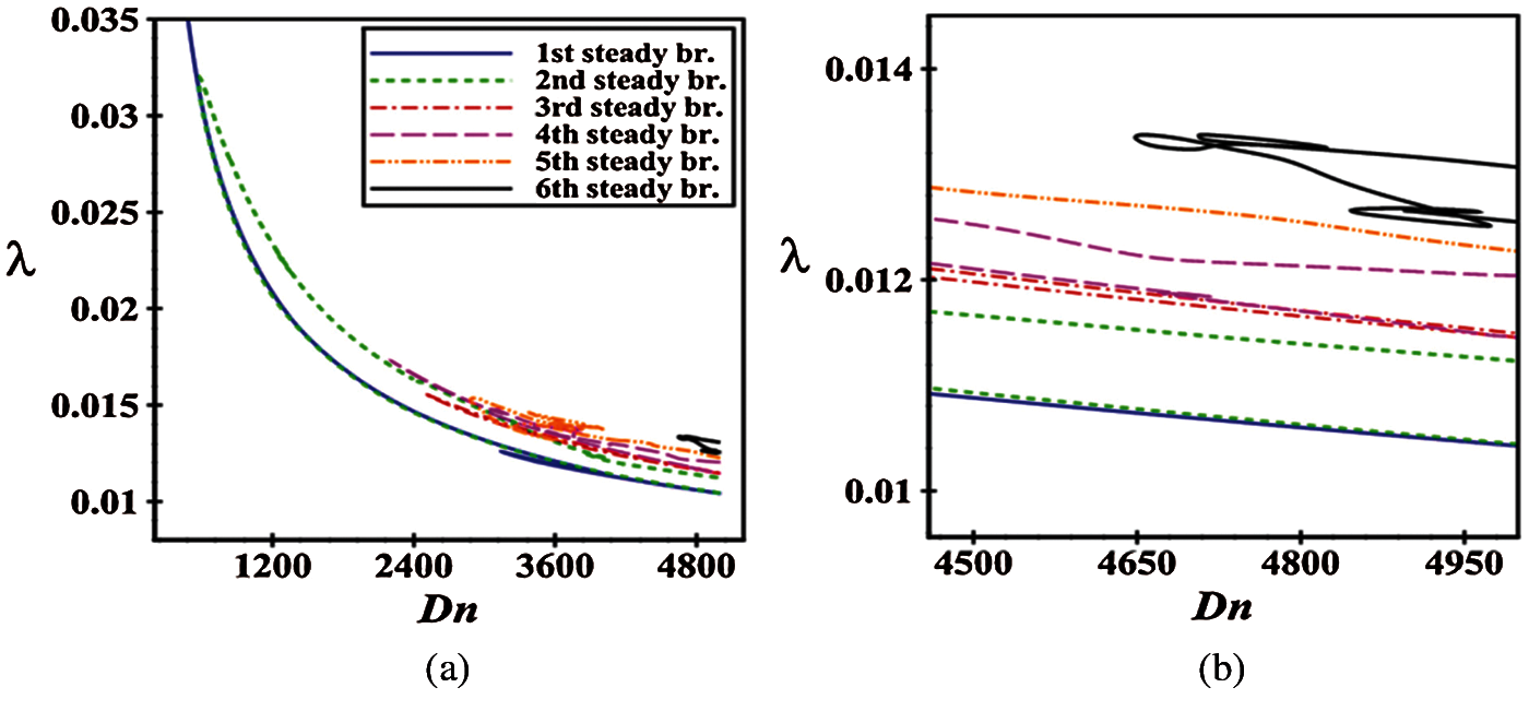
Figure 2: (a) Branching structure of SS; (b) Enlargement of Fig. 2a at large Dn’s
Here, we show the bar diagram of the vortex structure of secondary flows obtained at six branches of SS observed at a glance at various values of Dn for
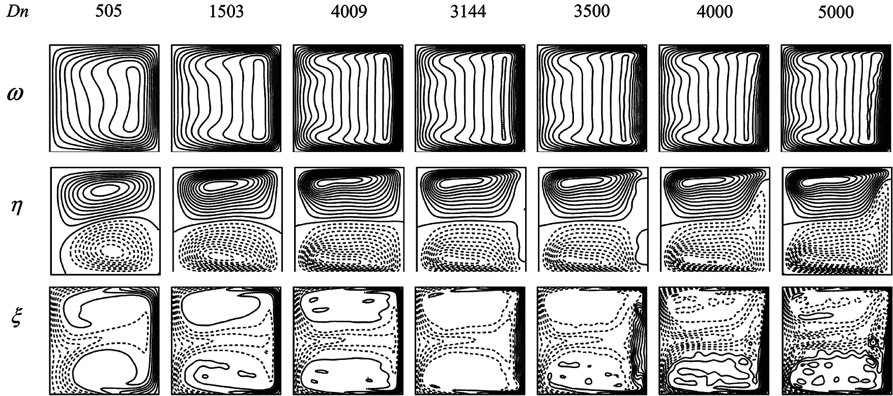
Figure 3: Velocity contour (top & middle) and isotherm (bottom) on the 1st branch
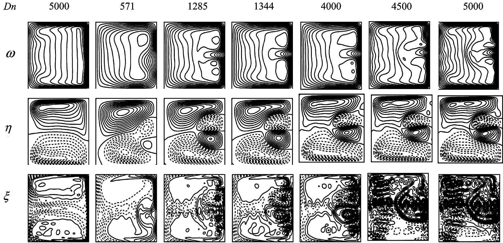
Figure 4: Velocity contour (top & middle) and isotherm (bottom) on the 2nd branch
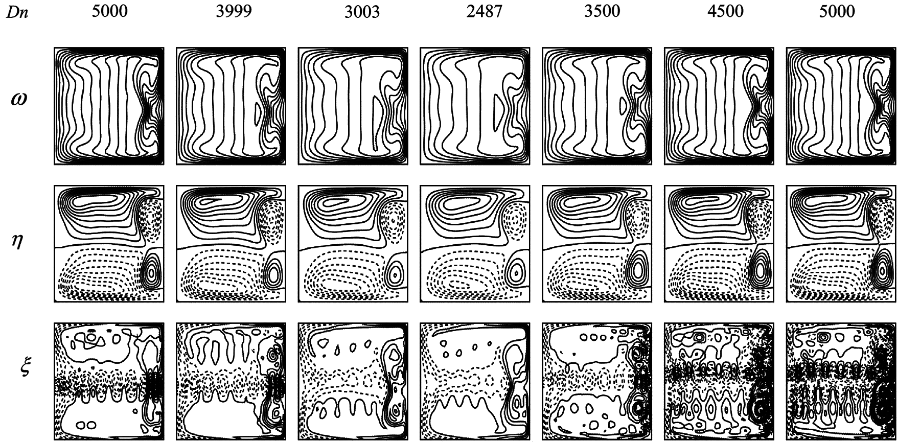
Figure 5: Velocity contour (top & middle) and isotherm (bottom) on the 3rd branch
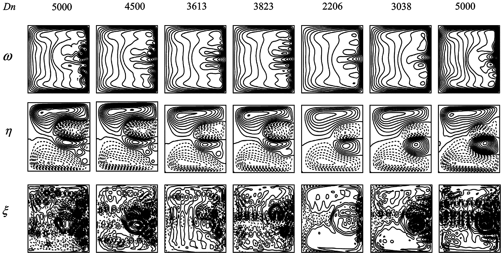
Figure 6: Velocity contour (top & middle) and isotherm (bottom) on the 4th branch
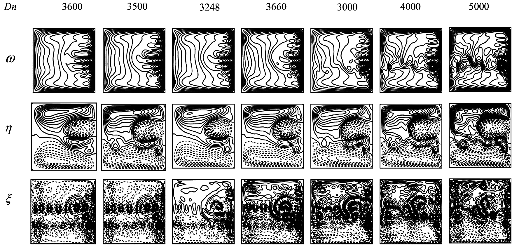
Figure 7: Velocity contour (top & middle) and isotherm (bottom) on the 5th branch
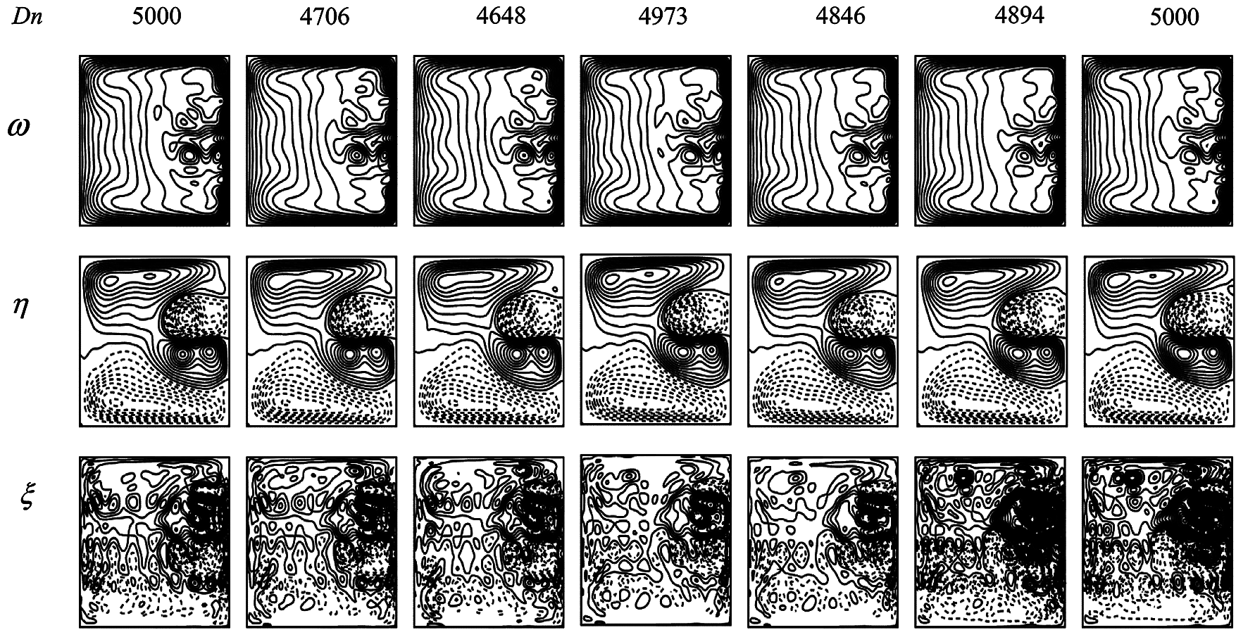
Figure 8: Velocity contour (top & middle) and isotherm (bottom) on the 6th branch
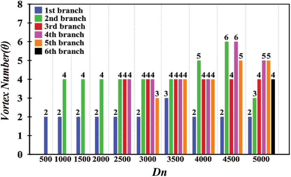
Figure 9: Vortex structure of secondary flow for steady branches for
An exhaustive investigation is presented for calculating the oscillating behavior with the
Next, we deliberated the oscillating behavior for
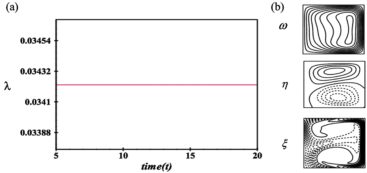
Figure 10: Transient solution for Tr = 500 (a) λ as a function of time (b) Velocity contour (top & middle) and isotherm (bottom) t = 5.0
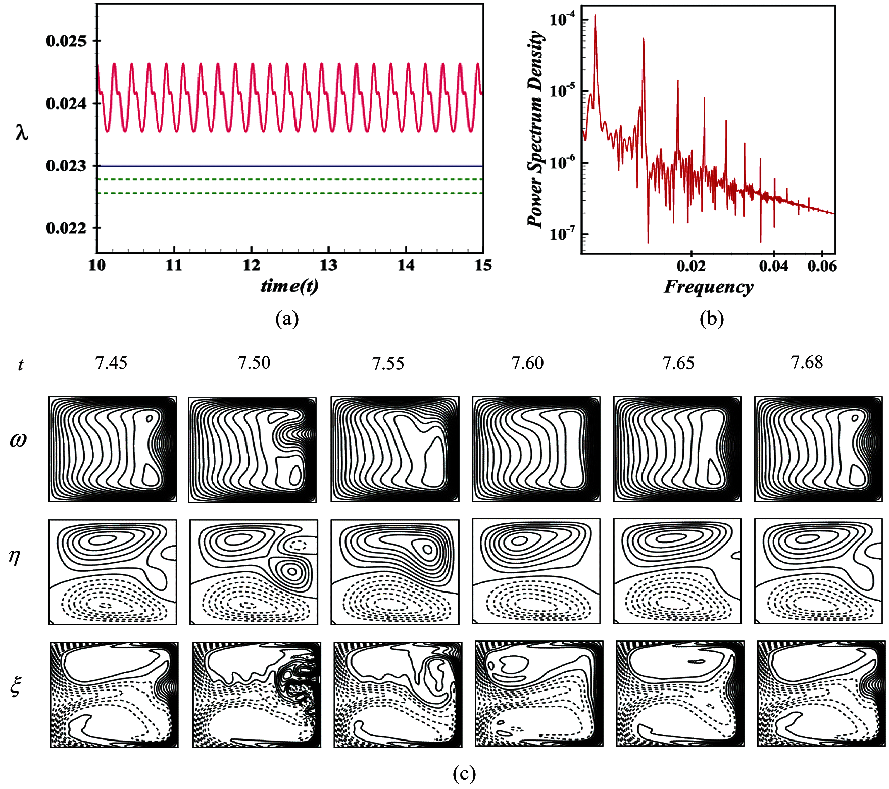
Figure 11: Transient solution for Dn = 1000 (a) λ as a function of time (b) P-S of (a) and (c) Velocity contour (top & middle) and isotherm (bottom)
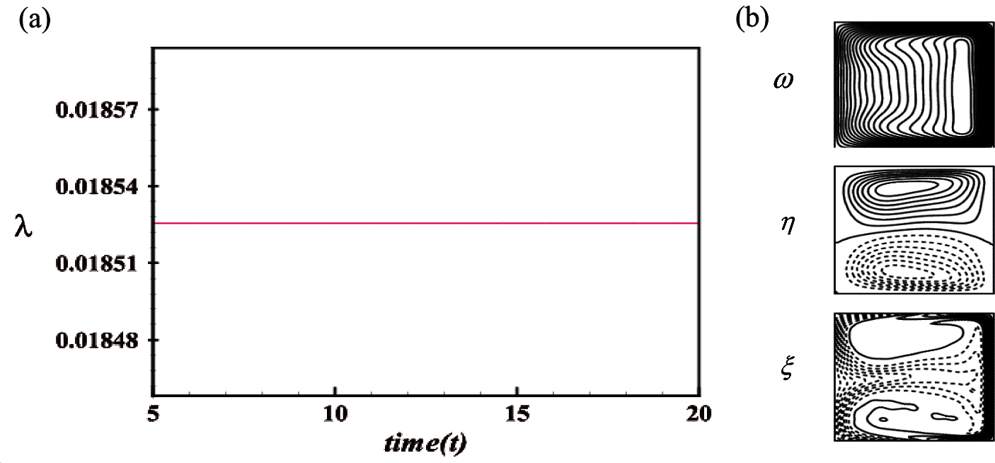
Figure 12: Transient solution for Tr = 1500 (a) λ as a function of time, (b) Velocity contour (top & middle) and isotherm (bottom) at t = 20
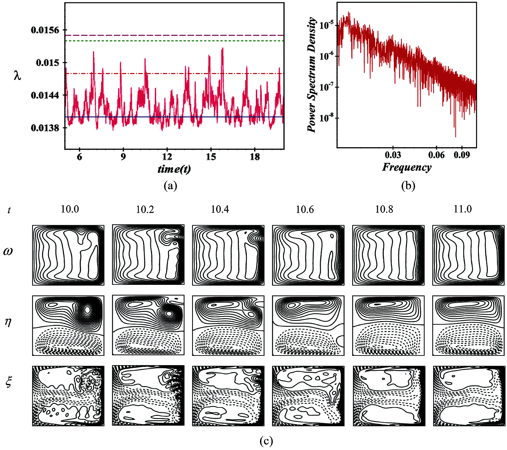
Figure 13: Transient solution for Dn = 2750 (a) λ as a function of time (b) P-S of (a) and (c) Velocity contour (top & middle) and isotherm (bottom)
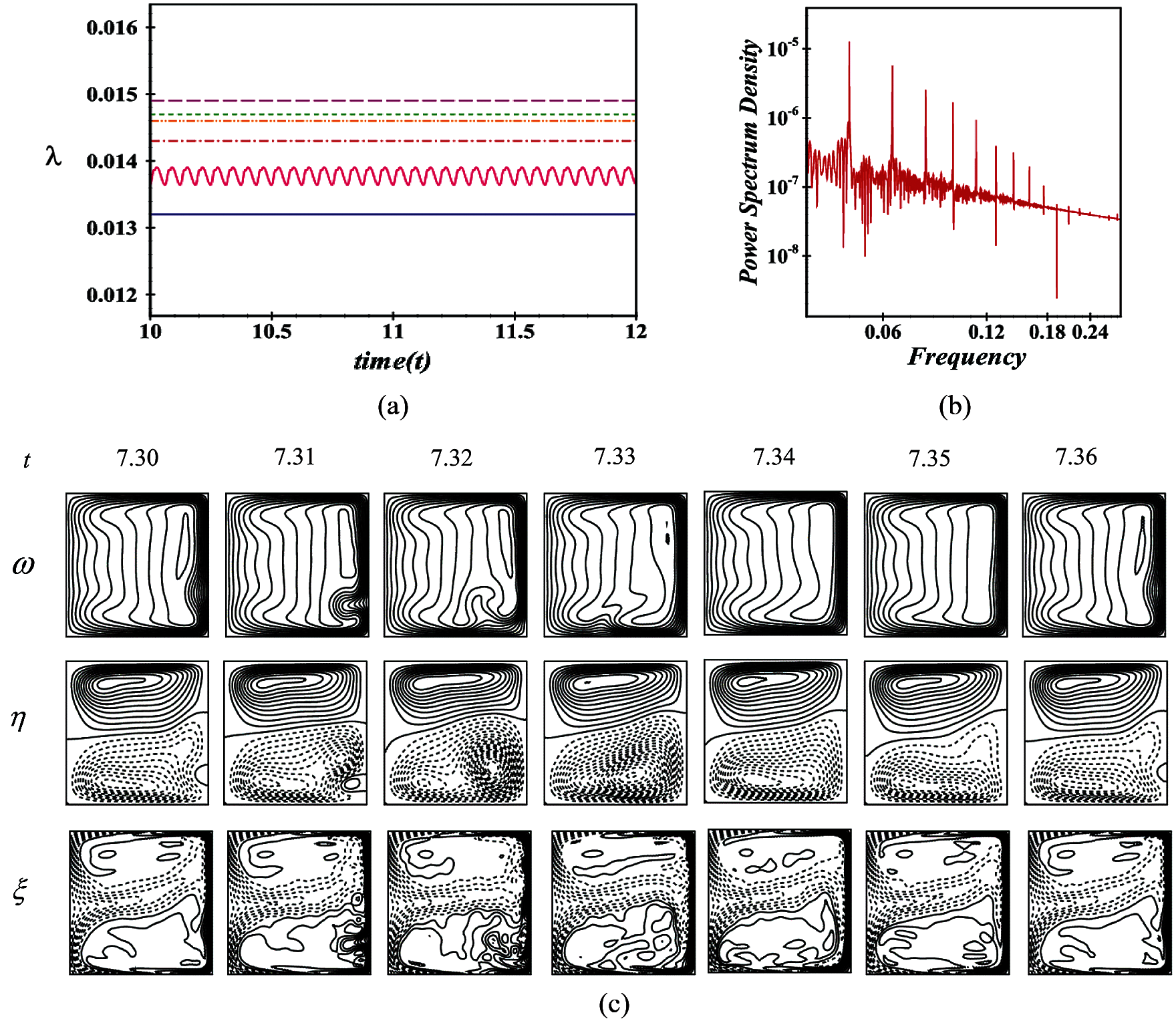
Figure 14: Transient solution for Dn = 3000 (a) λ as a function of time (b) P-S of (a) and (c) Velocity contour (top & middle) and isotherm (bottom)
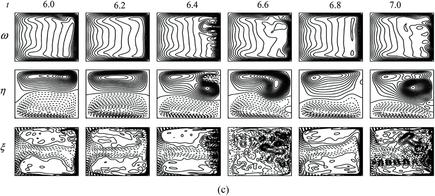
Figure 15: Transient solution for Dn = 3500 (a) λ as a function of time (b) P-S of (a) and (c) Velocity contour (top & middle) and isotherm (bottom)
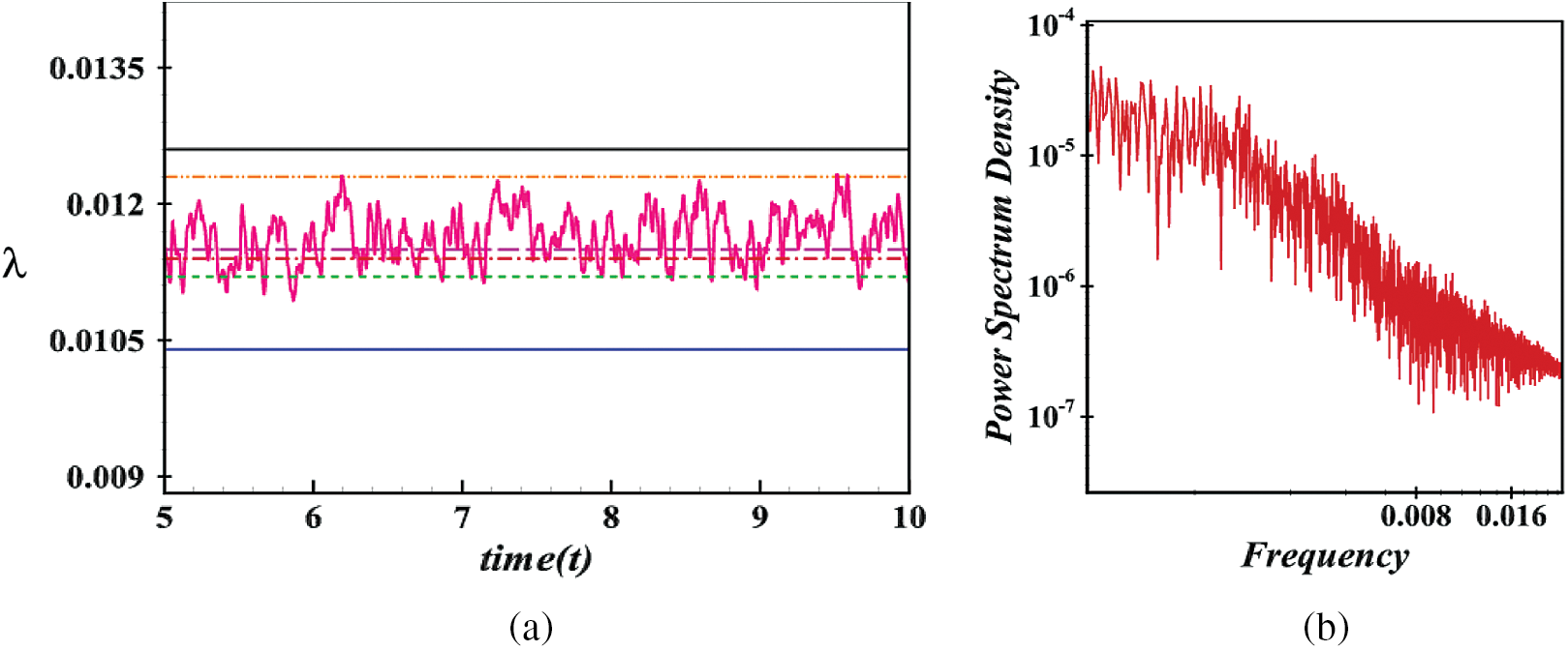
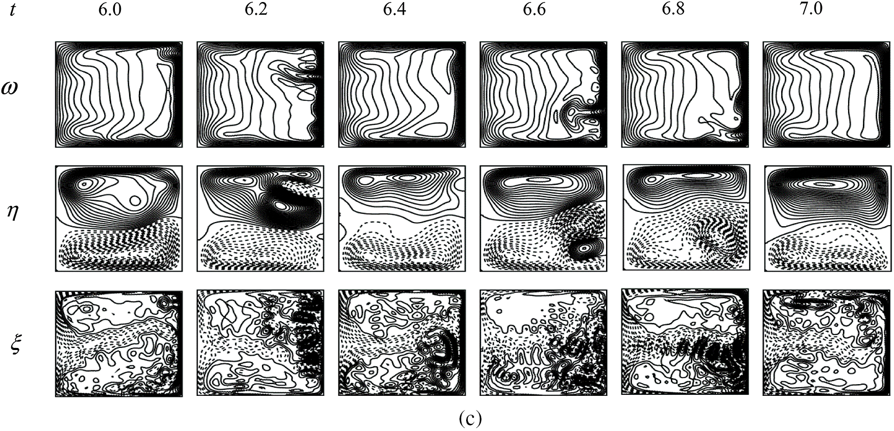
Figure 16: Transient solution for Dn = 5000 (a) λ as a function of time (b) P-S of (a) and (c) Velocity contour (top & middle) and isotherm (bottom)
4.3 Flow State and Vortex Structure
A schematic diagram of the variation of unsteady flow state with respect to Dn is shown in Fig. 17a. Here, the steady-state solution is denoted by squares, periodic or multi-periodic by circles and the chaotic by crosses. The intervals for the various US exist: steady-state;
In Fig. 18, we present a pie chart to show the percentage of unsteady flow state over the Dn number. Since each unsteady solution for Dn values has a region, so we have established the percentage of steady-state, periodic, and chaotic flow. As visualized in the pie chart described in Fig. 18, the steady-state flow covers almost 29% combining two ranges, whereas periodic is approximately 20% and chaotic 51%. It is observed that the chaotic flow covers the maximum flow region where the number of secondary vortices becomes significant.
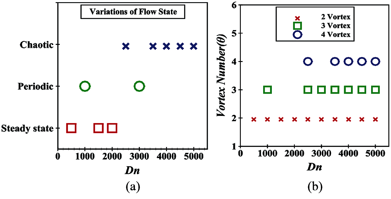
Figure 17: (a) UF characteristics over Dn, (b) Vortices of SF with regard to Dn for US
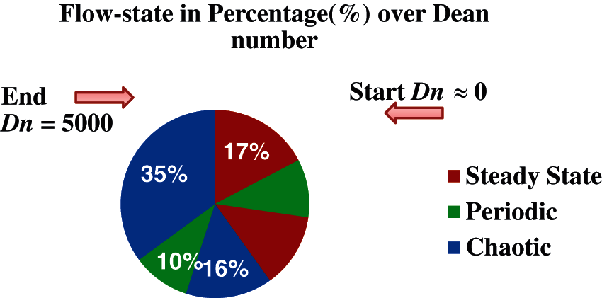
Figure 18: Percentage of unsteady flow state over Dn values
Here, heat transmission is analyzed by the study of temperature gradients (TG). As we know the TG can elucidate in which direction and at what rate the temperature changes around a particular location; therefore, TG on the cooled walls and heated walls are executed as displayed in Fig. 19. From Fig. 19a, it is seen that
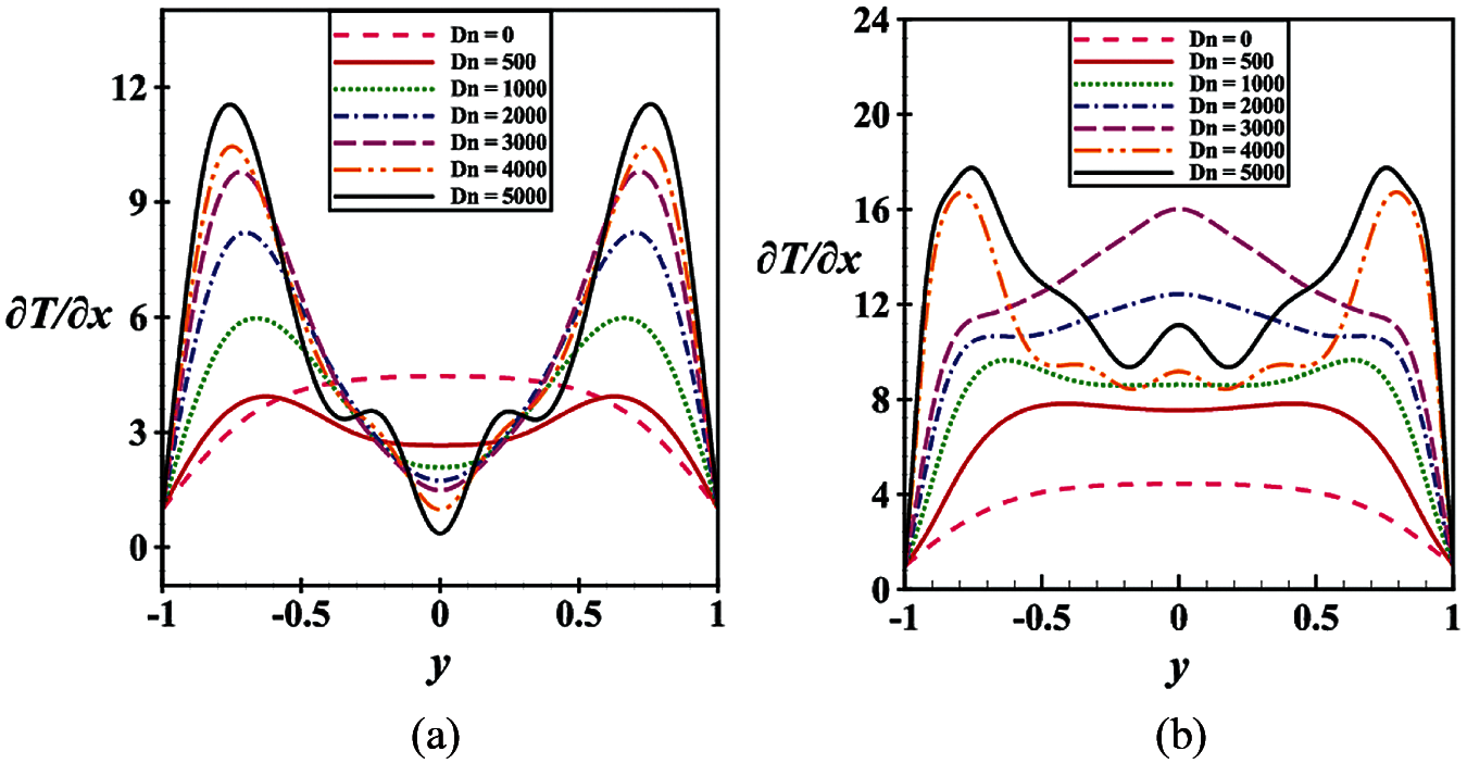
Figure 19: (a) TG at the cooling wall (b) TG at the heated walls
5.1 Comparison in the Dn vs. Nu (Dn~Nu) Plane
For validation, the current numerical results subject to heat transfer with the numerical data provided by Mondal et al. [36] and Wang et al. [37] are plotted graphically in the Dn vs. Nu plane in Fig. 20. The bullets indicate the intersecting point of the specific Dean number (Dn) corresponding to the Nusselt number (Nu). A comparison of the results obtained using the cooled surface is presented in Fig. 20, where it is noticed that the three lines of the graph relating to the heat transfer show almost the same trend. The overall result also agrees well with the above-mentioned two studies.
5.2 Comparison in the Secondary Vortex
In this sub-section, the validation of our findings by comparing with the published experimental results available in the literature is performed. Figs. 21a–21d present a relative comparison of our numerical findings with the established investigations by Bara et al. [38], Mees et al. [39], Wang et al. [22] for curvature
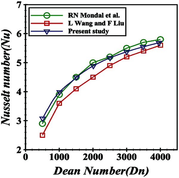
Figure 20: Comparison of the present study with the results by Mondal et al. [36] and Wang et al. [37]
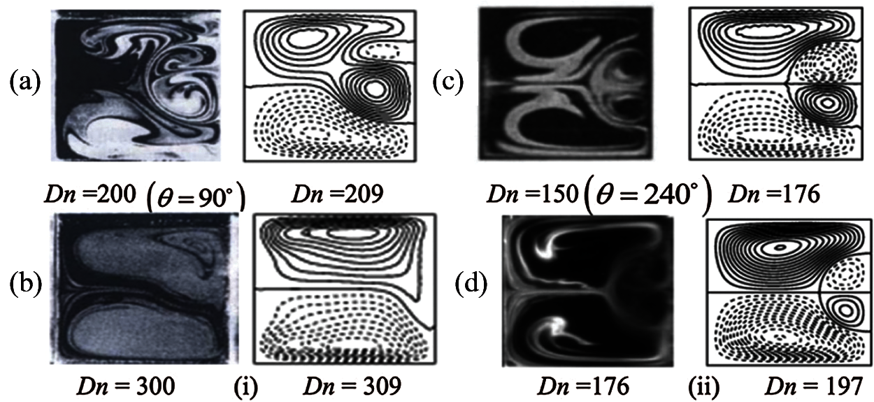
Figure 21: Investigational outcomes vs. numerical data. Left: Laboratory-based experimental results by (a) Bara et al. [38], (b) Mees et al. [39], (c) Wang et al. [22], and (d) Chandratilleke [40] and right: numerical results by the authors
Now we will deliberate the plausibility of applying 2D calculations to study bend channel flows in the present study. Mees et al. [39,41] observed traveling wave solutions in the study of BD flows. They observed the change of secondary flow pattern far downstream using a spiral duct, where Dn increases in the downstream due to an increase of the curvature. Wang et al. [22] showed that periodic flows can be analyzed precisely by 2D calculations. They showed that for an oscillating flow, there exists a close similarity between the flow observation at 270° and 2D calculation. The periodic oscillation, observed in the cross-section of their duct, was truly a traveling wave advancing in the downstream direction that was justified by a 3D study of BSD flows by Yanase et al. [42]. Therefore, it is found that 2D calculations can accurately predict the existence of 3D traveling wave solutions by showing an appearance of 2D periodic oscillation. There is some other evidence showing that the existence of chaotic or turbulent flow may be predicted by 2D analysis. Yamamoto et al. [43] investigated helical pipe flows by 2D perturbations and compared the results with their experimental data, where they observed a good match between the numerical and the experimental data, which shows that even the transition to chaos can be predicted by 2D analysis. The transition from periodic oscillation to chaotic state, obtained by the 2D calculation in the present paper, may correspond to the destabilization of travelling waves in the BD flows like that of Tollmien-Schlichting waves in a boundary layer. Besides, 2D analysis can accurately describe the asymptotic behavior of the flows and without having a significant knowledge on asymptotic behavior of the flows, it is difficult to have a good physical insight into the BD flows. Nevertheless, complete bifurcation study obtained by the 2D analysis in the present paper, which is hardly possible in 3D analysis, may give a firm framework for the 3D study of steady, periodic and chaotic flows in the bend channel. Our 2D analysis, therefore, may contribute to the study of real flows in the BD at some extent although 3D simulation can give more accurate results but it is expensive.
In this study, a spectral-based numerical approach on fluid flow through a BSD with bottom and outer-wall heated while the upper and inner walls in room temperature have been investigated for small curvature varying the Dean number for
• An asymmetric six branches of SSs with 2-6-vortex is found on various branches.
• Transient behavior, as well as PS density analysis, shows that the flow-state changes in the sequence \{steady state, multi-periodic, steady-state, chaotic, periodic, chaotic\} if Dn is increased.
• Flow transition is precisely determined, and it is found that the steady-state, periodic or multi-periodic, and chaotic solution exist in 2 different regions of Dn. The intervals for various US exist like steady-state for
• The study predicts that there exists a 2-vortex solution for steady-state, 2–3-vortex for periodic, 2–4-vortex for multi-periodic oscillation, while 2–6-vortex for the chaotic solution.
• Unsteady flow behavior shows that the steady-state flow remains approximately 29%, periodic 20%, and chaotic 51% in the entire flow region.
• The highly complex secondary flow field develops with higher Dn, and CHT is boosted significantly by the chaotic flow than other flow states.
• The study shows that the existence of axial velocity and wall pressure is greatly influenced by the Dean vortices. The present study also shows that the fluid mixing is certainly induced by the duct curvature and pressure gradient, and as a consequence, overall heat transfer is increased throughout the fluid in the curved channel.
We have plans to study MHD and nanofluid flow in a bent channel in future by CFD.
Funding Statement: The authors received no specific funding for this study.
Conflicts of Interest: The authors declare that they have no conflicts of interest to report regarding the present study.
1. Dean, W. R. (1927). Note on the motion of fluid in a curved pipe. The London, Edinburgh, and Dublin Philosophical Magazine and Journal of Science, 4(20), 208–223. DOI 10.1080/14786440708564324. [Google Scholar] [CrossRef]
2. Rudolf, P., Desová, M. (2007). Flow characteristics of curved ducts. Applied and Computational Mechanics, 1, 255–264. [Google Scholar]
3. Norouzi, M., Biglari, N. (2013). An analytical solution for Dean flow in curved ducts with rectangular cross section. Physics of Fluids, 25(5), 53602. DOI 10.1063/1.4803556. [Google Scholar] [CrossRef]
4. Yanase, S., Goto, N., Yamamoto, K. (1989). Dual solutions of the flow through a curved tube. Fluid Dynamics Research, 5(3), 191–201. DOI 10.1016/0169-5983(89)90021-X. [Google Scholar] [CrossRef]
5. Nandakumar, K., Masliyah, J. H. (1982). Bifurcation in steady laminar flow through curved tubes. Journal of Fluid Mechanics, 119, 475–490. DOI 10.1017/S002211208200144X. [Google Scholar] [CrossRef]
6. Kao, H. C. (1992). Some aspects of bifurcation structure of laminar flow in curved ducts. Journal of Fluid Mechanics, 243(1), 519–539. DOI 10.1017/S0022112092002805. [Google Scholar] [CrossRef]
7. Ligrani, P. M., Niver, R. D. (1988). Flow visualization of Dean Vortices in a curved channel with 40 to 1 aspect ratio. The Physics of Fluids, 31(12), 3605–3617. DOI 10.1063/1.866877. [Google Scholar] [CrossRef]
8. Yanase, S., Nishiyama, K. (1988). On the bifurcation of laminar flows through a curved rectangular tube. Journal of the Physical Society of Japan, 57(11), 3790–3795. DOI 10.1143/JPSJ.57.3790. [Google Scholar] [CrossRef]
9. Finlay, W. H., Nandakumar, K. (1990). Onset of two-dimensional cellular flow in finite curved channels of large aspect ratio. Physics of Fluids A: Fluid Dynamics, 2(7), 1163–1174. DOI 10.1063/1.857617. [Google Scholar] [CrossRef]
10. Winters, K. H. (1987). A bifurcation study of laminar flow in a curved tube of rectangular cross-section. Journal of Fluid Mechanics, 180(1), 343–369. DOI 10.1017/S0022112087001848. [Google Scholar] [CrossRef]
11. Daskopoulos, P., Lenhoff, A. M. (1989). Flow in curved ducts: Bifurcation structure for stationary ducts. Journal of Fluid Mechanics, 203, 125–148. DOI 10.1017/S0022112089001400. [Google Scholar] [CrossRef]
12. Mondal, R. N. (2006). Isothermal and non-isothermal flows through curved ducts with square and rectangular cross sections (Ph.D Thesis). Department of Mechanical Engineering, Okayama University, Japan. [Google Scholar]
13. Mondal, R. N., Kaga, Y., Hyakutake, T., Yanase, S. (2007). Bifurcation diagram for two-dimensional steady flow and unsteady solutions in a curved square duct. Fluid Dynamics Research, 39(5), 413–446. DOI 10.1016/j.fluiddyn.2006.10.001. [Google Scholar] [CrossRef]
14. Mondal, R. N., Ray, S. C., Yanase, S. (2014). Combined effects of centrifugal and coriolis instability of the flow through a rotating curved duct with rectangular cross section. Open Journal of Fluid Dynamics, 4(1), 1–14. DOI 10.4236/ojfd.2014.41001. [Google Scholar] [CrossRef]
15. Watanabe, T., Yanase, S. (2013). Bifurcation study of three-dimensional solutions of the curved square-duct flow. Journal of the Physical Society of Japan, 82(7), 74402. DOI 10.7566/JPSJ.82.074402. [Google Scholar] [CrossRef]
16. Chen, K. T., Yarn, K. F., Chen, H. Y., Tsai, C. C., Luo, W. J. et al. (2017). Aspect ratio effect on laminar flow bifurcations in a curved rectangular tube driven by pressure gradients. Journal of Mechanics, 33(6), 831–840. DOI 10.1017/jmech.2017.93. [Google Scholar] [CrossRef]
17. Hasan, M. S., Mondal, R. N., Lorenzini, G. (2019). Numerical prediction of non-isothermal flow with convective heat transfer through a rotating curved square channel with bottom wall heating and cooling from the ceiling. International Journal of Heat and Technology, 37(3), 710–726. DOI 10.18280/ijht.370307. [Google Scholar] [CrossRef]
18. Hasan, M. S., Mondal, R. N., Lorenzini, G. (2020). Physics of bifurcation of the flow and heat transfer through a curved duct with natural and forced convection. Chinese Journal of Physics, 67(3), 428–457. DOI 10.1016/j.cjph.2020.07.004. [Google Scholar] [CrossRef]
19. Chanda, R. K., Hasan, M. S., Lorenzini, G., Mondal, R. N. (2021). Effects of rotation and curvature ratio on fluid flow and energy distribution through a rotating curved rectangular channel. Journal of Engineering Thermophysics, 30(2), 243–269. DOI 10.1134/S1810232821020089. [Google Scholar] [CrossRef]
20. Hasan, M. S., Mondal, R. N., Kouchi, T., Yanase, S. (2019). Hydrodynamic instability with convective heat transfer through a curved channel with strong rotational speed. AIP Conference Proceedings, 2121(1), 30006. DOI 10.1063/1.5115851. [Google Scholar] [CrossRef]
21. Chandratilleke, T. T., Nursubyakto, K. (2003). Numerical prediction of secondary flow and convective heat transfer in externally heated curved rectangular ducts. International Journal of Thermal Sciences, 42(2), 187–198. DOI 10.1016/S1290-0729(02)00018-2. [Google Scholar] [CrossRef]
22. Wang, L., Yang, T. (2005). Periodic oscillation in curved duct flows. Physica D: Nonlinear Phenomena, 200(3–4), 296–302. DOI 10.1016/j.physd.2004.11.003. [Google Scholar] [CrossRef]
23. Mondal, R. N., Islam, S., Uddin, K., Hossain, A. (2013). Effects of aspect ratio on unsteady solutions through curved duct flow. Applied Mathematics and Mechanics, 34(9), 1107–1122. DOI 10.1007/s10483-013-1731-8. [Google Scholar] [CrossRef]
24. Nowruzi, H., Ghassemi, H., Nourazar, S. S. (2019). Linear hydrodynamic stability of fluid flow in curved rectangular ducts: Semi-analytical study. Journal of Mechanics, 35(5), 747–765. DOI 10.1017/jmech.2019.5. [Google Scholar] [CrossRef]
25. Islam, M. Z., Mondal, R. N., Rashidi, M. M. (2017). Dean-Taylor flow with convective heat transfer through a coiled duct. Computers & Fluids, 149(6), 41–55. DOI 10.1016/j.compfluid.2017.03.001. [Google Scholar] [CrossRef]
26. Chanda, R. K., Hasan, M. S., Alam, M. M., Mondal, R. N. (2020). Hydrothermal behavior of transient fluid flow and heat transfer through a rotating curved rectangular duct with natural and forced convection. Mathematical Modelling of Engineering Problems, 7(4), 501–514. DOI 10.18280/mmep.070401. [Google Scholar] [CrossRef]
27. Dolon, S. N., Hasan, M. S., Lorenzini, G., Mondal, R. N. (2021). A computational modeling on transient heat and fluid flow through a curved duct of large aspect ratio with centrifugal instability. The European Physical Journal Plus, 136(4), 1–27. DOI 10.1140/epjp/s13360-021-01331-0. [Google Scholar] [CrossRef]
28. Lin, R., Wang, X., Xu, W., Jia, X., Jia, Z. (2019). Experimental and numerical study on forced convection heat transport in eccentric annular channels. International Journal of Thermal Sciences, 136, 60–69. DOI 10.1016/j.ijthermalsci.2018.10.003. [Google Scholar] [CrossRef]
29. Mondal, R. N., Watanabe, T., Hossain, M. A., Yanase, S. (2017). Vortex-structure and unsteady solutions with convective heat transfer through a curved duct. Journal of Thermophysics and Heat Transfer, 31(1), 243–254. DOI 10.2514/1.T4913. [Google Scholar] [CrossRef]
30. Zhang, W., Wei, Y., Dou, H. S., Zhu, Z. (2018). Transient behaviors of mixed convection in a square enclosure with an inner impulsively rotating circular cylinder. International Communications in Heat and Mass Transfer, 98, 143–154. DOI 10.1016/j.icheatmasstransfer.2018.08.016. [Google Scholar] [CrossRef]
31. Hasan, M. S., Mondal, R. N., Lorenzini, G. (2019). Centrifugal instability with convective heat transfer through a tightly coiled square duct. Mathematical Modelling of Engineering Problems, 6(3), 397–408. DOI 10.18280/mmep.060311. [Google Scholar] [CrossRef]
32. Zhao, H., Li, X., Wu, Y., Wu, X. (2020). Friction factor and Nusselt number correlations for forced convection in helical tubes. International Journal of Heat and Mass Transfer, 155(20), 119759. DOI 10.1016/j.ijheatmasstransfer.2020.119759. [Google Scholar] [CrossRef]
33. Hasan, M. S., Islam, M. M., Ray, S. C., Mondal, R. N. (2019). Bifurcation structure and unsteady solutions through a curved square duct with bottom wall heating and cooling from the ceiling. AIP Conference Proceedings, 2121(1), 50003. DOI 10.1063/1.5115890. [Google Scholar] [CrossRef]
34. Chanda, R. K., Hasan, M. S., Alam, M. M., Mondal, R. N. (2021). Taylor-heat flux effect on fluid flow and heat transfer in a curved rectangular duct with rotation. International Journal of Applied and Computational Mathematics, 7(4), 146. DOI 10.1007/s40819-021-00986-8. [Google Scholar] [CrossRef]
35. Gottlieb, D., Orszag, S. A. (1977). Numerical analysis of spectral methods: Theory and applications. Society for Industrial and Applied Mathematics, 1–170. DOI 10.1137/1.9781611970425. [Google Scholar] [CrossRef]
36. Mondal, R. N., Kaga, Y., Hyakutake, T., Yanase, S. (2006). Effects of curvature and convective heat transfer in curved square duct flows. ASME, Journal of Fluids Engineering, 128(9), 1013–1022. DOI 10.1115/1.2236131. [Google Scholar] [CrossRef]
37. Wang, L., Liu, F. (2007). Forced convection in tightly coiled ducts: Bifurcation in a high Dean number region. International Journal of Non-Linear Mechanics, 42(8), 1018–1034. DOI 10.1016/j.ijnonlinmec.2007.05.005. [Google Scholar] [CrossRef]
38. Bara, B., Nandakumar, K., Masliyah, J. (1992). An experimental and numerical study of the Dean problem: Flow development towards two-dimensional multiple solutions. Journal of Fluid Mechanics, 244(1), 339–376. DOI 10.1017/S0022112092003100. [Google Scholar] [CrossRef]
39. Mees, P. A., Nandakumar, K., Masliyah, J. H. (1996a). Instability and transitions of flow in a curved square duct: The development of two pairs of Dean vortices. Journal of Fluid Mechanics, 314, 227–246. DOI 10.1017/S0022112096000298. [Google Scholar] [CrossRef]
40. Chandratilleke, T. T. (2001). Secondary flow characteristics and convective heat transfer in a curved rectangular duct with external heating. 5th World Conference on Experimental Heat Transfer, Fluid Mechanics and Thermodynamics. Thessaloniki, Greece. [Google Scholar]
41. Mees, P. A. J., Nandakumar, K., Masliyah, J. H. (1996b). Steady spatial oscillations in a curved duct of square cross-section. Physics of Fluids, 8(12), 3264–3270. DOI 10.1063/1.869108. [Google Scholar] [CrossRef]
42. Yanase, S., Watanabe, T., Hyakutake, T. (2008). Traveling-wave solutions of the flow in a curved-square duct. Physics of Fluids, 20(124101), 1–8. DOI 10.1063/1.3029703. [Google Scholar] [CrossRef]
43. Yamamoto, K., Yanase, S., Jiang, R. (1998). Stability of flow in helical tube. Fluid Dynamics Research, 22(3), 153–170. DOI 10.1016/S0169-5983(97)00032-4. [Google Scholar] [CrossRef]
 | This work is licensed under a Creative Commons Attribution 4.0 International License, which permits unrestricted use, distribution, and reproduction in any medium, provided the original work is properly cited. |