| Energy Engineering |
DOI: 10.32604/ee.2022.015133
ARTICLE
Research on the Impacts of the Inertia and Droop Control Gains from a Variable-Speed Wind Turbine Generator on the Frequency Response
1School of Electrical Engineering, Nantong University, Nantong, China
2School of Electrical Engineering, Northeast Electric Power University, Jilin, China
3Transcell Technology, Nanjing, China
*Corresponding Authors: Xinsong Zhang. Email: prettypebble@163.com; Haochen Sun. Email: jason.sun@transcell.com
Received: 24 November 2020; Accepted: 12 April 2021
Abstract: System frequency must be kept very close to its nominal range to ensure the stability of an electric power grid. Excessive system frequency variations are able to result in load shedding, frequency instability, and even generator damage. With increasing wind power penetration, there is rising concern about the reduction in inertia response and primary frequency control in the electric power grid. Converter-based wind generation is capable of providing inertia response and primary frequency response; nevertheless, the primary frequency and inertia responses of wind generation are different from those of conventional synchronous fleets; it is not completely understood how the primary frequency and inertia responses affect the given system under various disturbances and available kinetic energy levels. Simulations are used to investigate the influences of inertia and droop control strategies on the dynamic frequency responses, particularly the index of the second frequency drop under various disturbance and wind conditions. A quantitative analysis provides insight into setting of inertia and droop control coefficients for various wind and disturbance conditions to facilitate adequate dynamic frequency responses during frequency events.
Keywords: Wind power; inertia control; droop control; frequency stability
The ability of an electric power system to maintain its frequency at an acceptable level is crucial for power system reliability [1]. To this end, an electric power system is required to provide adequate frequency responses (inertia response, primary frequency response and so on) against disturbances; otherwise, frequency variations might lead to load shedding, frequency instability, and even generator damage [2]. The inertia response of synchronous generators is the inherent response by injecting (or extracting) kinetic energy into (or from) the rotating masses of the generator, which is benefical for slowing the speed of system frequency deviation. Primary frequency control increases or decreases the mechanical power of a synchronous generator according to its frequency excursions by using a turbine governor, which is benefical for boosting the frequency nadir and stabilizing the system frequency.
Variable speed wind turbine generators including doubly-fed induction generator (DFIG, Type III) and full-scale converter wind turbine generators (Type IV) rarely contribute to primary frequency response; this is because they are not synchronous with the power grid [3–5]. The lower system inertia and displacements of primary frequency response result in the large rate of change of frequency and low frequency nadir. This may translate to a decline in the stability and reliability of power system. Accordingly, variable speed wind turbine generators should support dynamic frequency response so that wind energy penetration can be heightened while preserving the reliability of power system [6,7].
Many studies have been investigated temporary frequency support function strategies that release stored rotational kinetic energy produced by the rotating masses of a variable speed wind turbine generator to support dynamic frequency response [8–16]. These strategies add additional loops to the rotor side converter (RSC) controller of a DFIG based on the measured frequency: the rate of change of frequency (df/dt) loop and system frequency excursion, these strategies are named as inertia control and droop control strategies, respectively [8–10]. The performance of inertia control strategy with various control coefficients is studied in [11]. This shows that the inertia control strategy can only provide temporary power support to improve the maximum df/dt and does not greatly contribute to the improvement of the frequency nadir. The study of [12] investigated the influences of converter current limits and auxiliary loop parameters on inertia control under rated wind speed. The capability to supply temporary excess active output power support for a DFIG was quantified in [13,14]. This research demonstrated that high wind conditions retain large capability to provide temporary output power. In [15,16], the authors analyzed dynamic frequency response with various inertia and droop control coefficients. They demonstrated that large control coefficients conduce to improve the maximum df/dt and frequency nadir. Nevertheless, few researches have examinzed how various wind speed conditions impact the second frequency drop. Moreover, few studies have addressed how various sizes of disturbance impact dynamic frequency response.
This paper focuses on analyzing the impact of the inertia and droop control coefficients from a DFIG on dynamic frequency response. To this end, simulations with various wind conditions and disturbances are performed by using different control coefficients based on an electromagnetic transient program (restructured version simulator).
2 Fundamental Features of Inertia and Droop Control Strategies from a DFIG
This section addresses the fundamental features of the inertia control strategy and droop control strategy. In addition, this paper analyzes the temporary active power support capability of employing the rotational kinetic energy stored in the rotating masses of a DFIG without de-loading operation. Figs.1 and 2 show the structures of the inertia and droop control strategies.
2.1 Inertia Control Strategy of a DFIG
As shown in Fig. 1, the features of inertia control strategy are similar to those of the inertia response of conventional synchronous generators, which release the kinetic energy from the turbine to arrest the frequency decline.
To perform inertia control from a DFIG, a supplementary control on the basis of df/dt is included combined with the maximum power point tracking (MPPT) control loop in the RSC controller. The output of the inertia control strategy, ∆Pin, is given by:
where Kin is the coefficient of the inertia control strategy and fsys means the measured system frequency in p.u., dfsys/dt is the rate of change of the frequency.

Figure 1: Structure of the inertia control strategy
The inertia control strategy is able to inject active power into the grid according to dfsys/dt. Short and quick active power injection benefits the dynamic frequency response by essentially limiting the maximum dfsys/dt. This means that, during the initial stage of a frequency contingence, dfsys/dt is large value so that the output power of the inertia control strategy is large. Nevertheless, with time, dfsys/dt decreases and becomes zero at a new steady state. As a result, the contribution to improving the frequency nadir is poor, as shown in Fig. 3. Furthermore, dfsys/dt changes its sign from negative value to positive value after the frequency rebounding. Such an effect has an adverse impact on improving the frequency nadir and may result in a large second frequency drop.
2.2 Droop Control Strategy of a DFIG
As shown in Fig. 2, the features of the droop control strategy are similar to those of the governor response of conventional synchronous generators, which increases the mechanical input power based on the measured rotating speed deviation. Unlike in the governor response, the droop control strategy from DFIGs releases kinetic energy from rotating masses rather than reserve power.
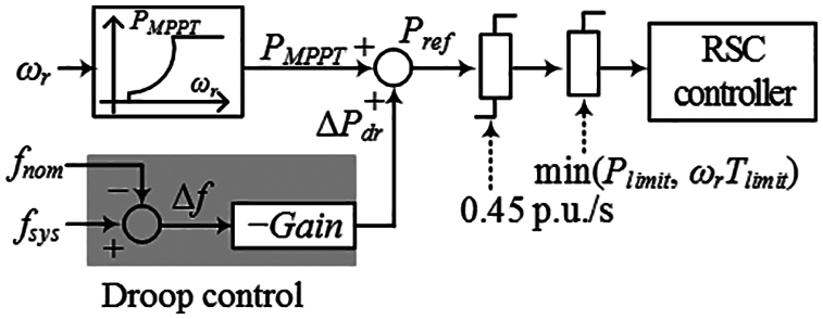
Figure 2: Structure of the droop control strategy
To perform droop control from a DFIG, an additional control loop is included on the basis of frequency deviation and combined with the MPPT control loop. The output of the droop control strategy loop (∆Pdr) can be given as:
where Kdr means the gain of the droop control strategy and fnom denotes as the nominal frequency.
The power injected to the grid from the droop control loop strongly depends on the frequency deviation. As shown in Fig. 3, the injected power around the frequency nadir is sufficiently large to improve the frequency nadir effectively. Nonetheless, the drawback of this control method is that the power injected during the initial stage of a frequency contingence is small so that the contribution for support for the maximum df/dt is limited.
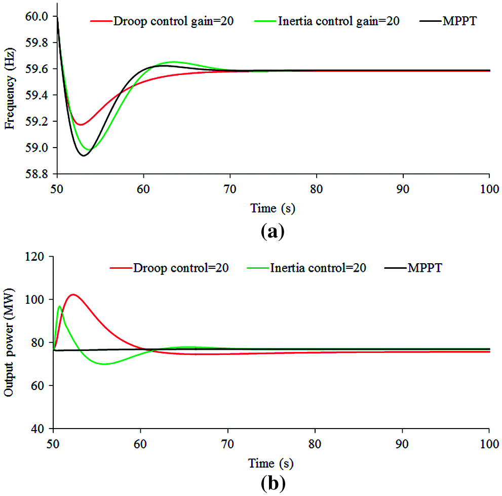
Figure 3: Results following a loss of synchronous generator when DFIG performs inertia and droop control strategies. (a) System frequency; (b) Output of the wind power plant
2.3 Temporary Output Power Support Capability of a DFIG
The rotational kinetic energy stored in the rotating turbine of a DFIG (EDFIG) can be represented as:
where JDFIG means the moment of inertia of a DFIG. ωr means the rotor speed of a DFIG.
The available kinetic energy of a DFIG can be given as:
where HDFIG means the inertia constant of a DFIG. ω0 and ωmin represent the rotor speed of a DFIG prior to disturbance and the minimum rotor speed limit. In this study, the kinetic energy of a DFIG is normalized by its rated capacity; thus, the unit of the normalized kinetic energy is seconds [17].
Fig. 4 displays the temporary output power support capability of a DFIG. From Fig. 4 and (4), it is evident that the temporary output power support potential of a DFIG is proportional to the rotor speed. This means that the available kinetic energy of a DFIG during the high speed region of the rotor is greater than that during the low speed region.
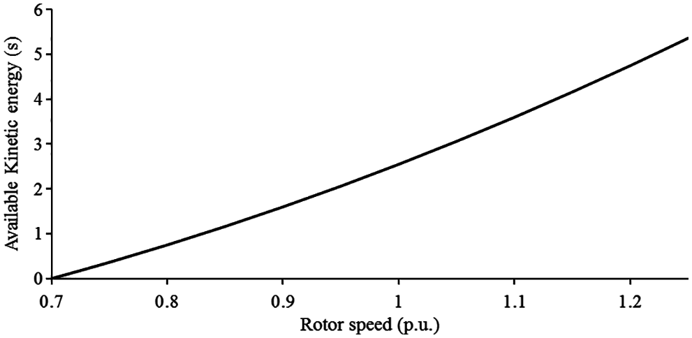
Figure 4: Available kinetic energy of a DFIG
As in (1) and (2), short and quick active power injection relies on the frequency measurements and control coefficients; the frequency measurements including the df/dt and frequency deviation are dependent on the power system conditions and sizes of disturbance, which are uncontrollable. Hence, a dynamic frequency response is primarily determined by the control coefficients of inertia control strategy and droop control strategy. To improve dynamic frequency response, it is important to understand how various wind speed conditions impact the second frequency drop and how various sizes of disturbance impact dynamic frequency response.
The model system shown in Fig. 5 is used to investigate the performance of the system regarding the impact of the control coefficients of the inertia and droop control strategies on the dynamic frequency response. It includes a DFIG-based wind power plant and an electric power grid including five synchronous generators, and static and motor loads are modeled. Six SGs are included in the model system: two 100-MVA SGs, two 150-MVA SGs, and two 200-MVA SGs. For simplicity, all SGs are modeled as steam turbine generators, and the droop gains are set to 5%. The inertia time constants of the SGs are set to 5 s for the 200 MVA SGs, 4.3 s for the 150 MVA SGs, and 4 s for the 100 MVA SGs.
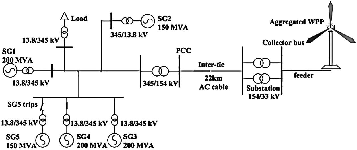
Figure 5: Model system
3.1 Conventional Synchronous Generators
To benchmark the power system with a low ramping ability, all conventional synchronous generators are modeled as steam turbine generators. Fig. 6 shows the IEEEG1 steam governor model, as in [18]; and the droop setting for the synchronous generator are set to 5%, which is the typical droop setting of the stream turbine. Moreover, secondary frequency control of conventional synchronous generators is not considered because the timeframe of the secondary frequency control is significantly more than that of primary frequency control; as a result, the system frequency is not fully recovered to 60 or 50 Hz.
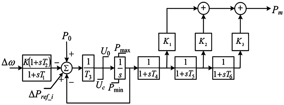
Figure 6: IEEEG1 steam governor model
Mechanical power extracted by a DFIG is expressed in (5) and depends on the air density ρ, wind turbine swept area A, wind speed vw, tip-speed ratio λ, and pitch angle β.
where R represents the radius of the wind turbine.
As in [19], the power coefficient cp is a nonlinear function as in (6).
where the tip-speed ratio λ is given as:
From (5) to (8), it is evident that the output power of a DFIG is strongly dependent on the rotor speed when other parameters of a DFIG are fixed.
cp retains a maximum value (cP, max) at the optimal λ (λopt) when β = 0°. At λopt, a DFIG can extract the maximum power from wind. Substituting (8) in (5), the active power reference for MPPT operation, PMPPT, can be represented as:
where kg represents a constant coefficient of MPPT operation and is set to 0.512.
The power reference for inertia control or droop control strategy is limited by the maximum power limiter and rate of change of power limiter to protect the DFIG. The maximum power limiter is set to 110% of the nominal active power of a DFIG, as in [3]; the rate of change of power limiter is set to 0.45 p.u./s, as in [3,20].
The DFIG calculates the grid frequency used for inertia and droop control without the additional information from a higher level controller. Moreover, inertia time constant for a 5-MW DFIG is set to 5 s including 4 s of induction generator and 1 s of the wind turbine. The detailed parameters are shown in Table 1.

4 Simulations with Various Control Coefficients of the Inertia and Droop Control on the Dynamic Frequency Response
To investigate the impact of the control coefficients of the inertia and droop control on the dynamic frequency response, the maximum rate of change of frequency, value of the frequency nadir, and second frequency drop are compared under different wind conditions and disturbances.
As a disturbance, SG5, which is supplying 70 and 110 MW, is assumed to be tripped out at 50 s. 8 and 10 m/s are considered as various wind conditions in all simulation results.
4.1 Effects of the Available Kinetic Energy and Control Strategies on Dynamic Frequency Response
The kinetic energy available of a DFIG differs from low wind conditions to high wind conditions. Thus, this subsection describes the effects of 10 and 8 m/s on the performance of inertia and droop control strategies when using various control coefficients.
4.1.1 Effects of the Inertia Control Strategy from a DFIG with the Wind Speeds of 8 and 10 m/s
The effects of inertia control strategy coefficient Kin on the dynamic frequency response with various wind speeds are showed in Figs. 7–10. In this case, only inertia control strategy is applied on the DFIG.
In the case of 10 m/s (green line), increasing the control coefficient from zero to 50, the frequency nadir is improved from 59.347 to 59.401 Hz; the maximum df/dt is reduced from −0.400 to −0.304 Hz/s. For 8m/s (black line), the frequency nadir is improved from 59.347 to 59.404 Hz; the maximum df/dt is reduced from −0.403 to −0.307 Hz/s. These indices are plotted in Figs. 7 and 8. The frequency nadir and maximum df/dt of 10 m/s are almost the same as those in 8 m/s. This is because the incremental powers of inertia control strategy with various wind conditions are almost the same calculated by using (1). The basic observation is that under various wind conditions, increasing the coefficient of inertia control strategy has a definitely positive influence on the dynamic frequency response including the frequency nadir and maximum df/dt.
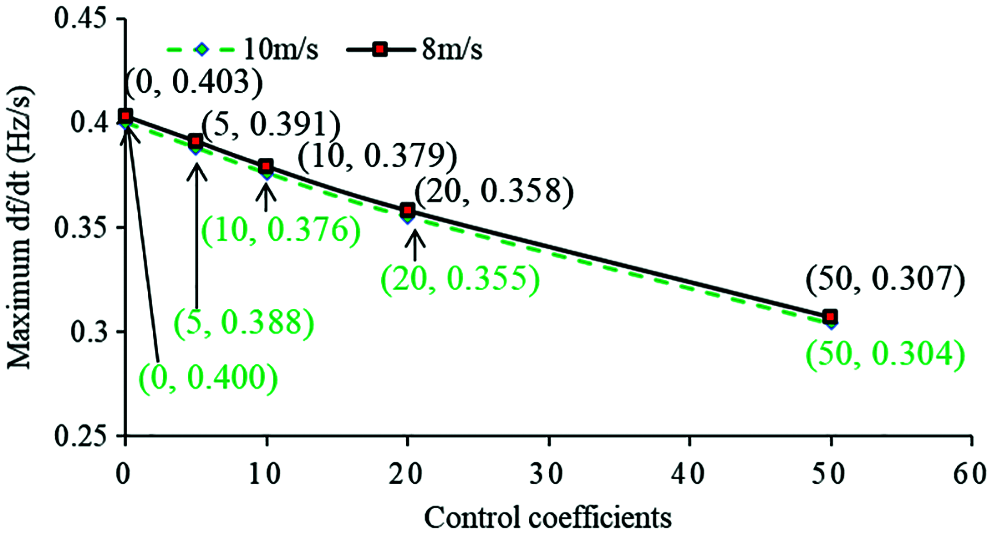
Figure 7: Absolute value of maximum df/dt with different inertia control coefficients
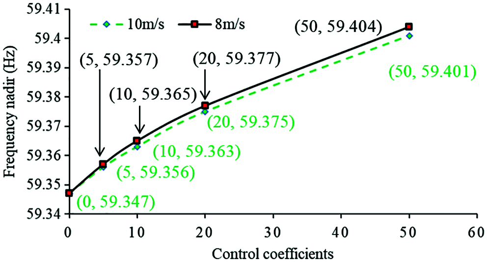
Figure 8: Frequency nadirs with different inertia control coefficients
The results of output power and rotor speed of a DFIG are illustrated in Figs. 9 and 10. The increasing coefficients of inertia control strategy boost the peak output power and the rotor speed reduction. Therefore, with the increasing coefficients of inertia control, the dynamic frequency response becomes better.
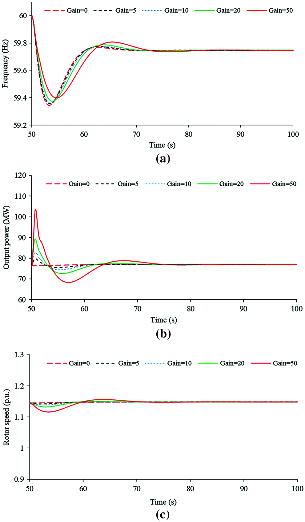
Figure 9: Simulation results of inertia control strategy using various control coefficients under the wind speed of 10 m/s: (a) System frequencies; (b) Active powers; (c) Rotor speeds
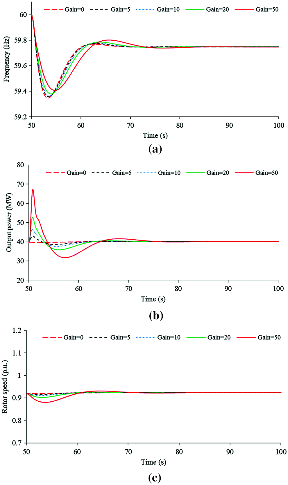
Figure 10: Simulation results of inertia control strategy using various control coefficients under the wind speed of 8 m/s: (a) System frequencies; (b) Active powers; (c) Rotor speeds
4.1.2 Effects of the Droop Control Strategy from a DFIG with the Wind Speeds of 8 and 10 m/s
In this case, only droop control strategy is applied on the RSC controller of a DFIG. The effects of droop control strategy coefficient Kdr on the dynamic frequency response with various wind speeds are showed in Figs. 11–14.
As shown in Figs. 11 and 12, the control coefficient increases from zero to 50, the maximum df/dt is reduced from −0.400 to −0.339 Hz/s for the case of 10 m/s and from −0.403 to −0.342 Hz/s for the case of 8 m/s. The first frequency nadir is increased from 59.347 to 59.621 Hz for the case of 10 m/s and from 59.347 to 59.629 Hz for the case of 8 m/s. Nevertheless, for the case of 8 m/s, the second frequency nadirs (SFN) are caused when the coefficient is set to 40 and 50, which are 59.473 and 59.473 Hz, respectively and are lower than the first frequency nadir. The reason is that over-deceleration of the rotor speed, which results in a severe second frequency drop, is caused (see Fig. 14c). In addition, the output power is limited by the torque limit so that the frequency nadir of 10 m/s is slightly lower than that of 8 m/s (when the coefficient is set to 50). The basic observation is that increasing the coefficient of droop control strategy has a definitely positive influence on the dynamic frequency response including the frequency nadir and maximum df/dt. However, increasing coefficient of droop control beyond 30 cannot substantially contribute to the frequency nadir, even though it still improves the maximum df/dt when the wind speed is low. Furthermore, as the control coefficient increases, the second frequency nadir becomes low.
Compared to inertia control strategy, even though the same coefficient is applied, the droop control strategy is able to improve the frequency nadir, but it is deficient in improving the maximum df/dt. As the available kinetic energy becomes less, the likelihood of causing second frequency nadir becomes larger and further deteriorates the frequency nadir.
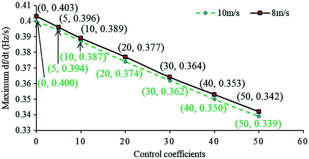
Figure 11: Absolute value of maximum df/dt with different droop control coefficients
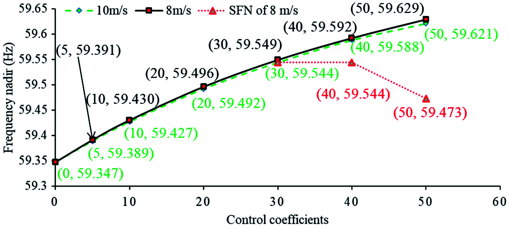
Figure 12: Frequency nadirs with different droop control coefficients
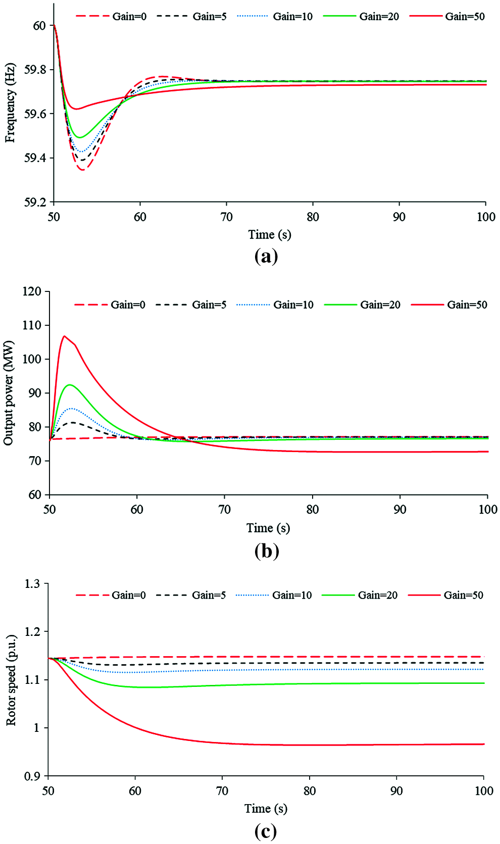
Figure 13: Simulation results of droop control strategy using various control coefficients under the wind speed of 10 m/s: (a) System frequencies; (b) Active powers; (c) Rotor speeds
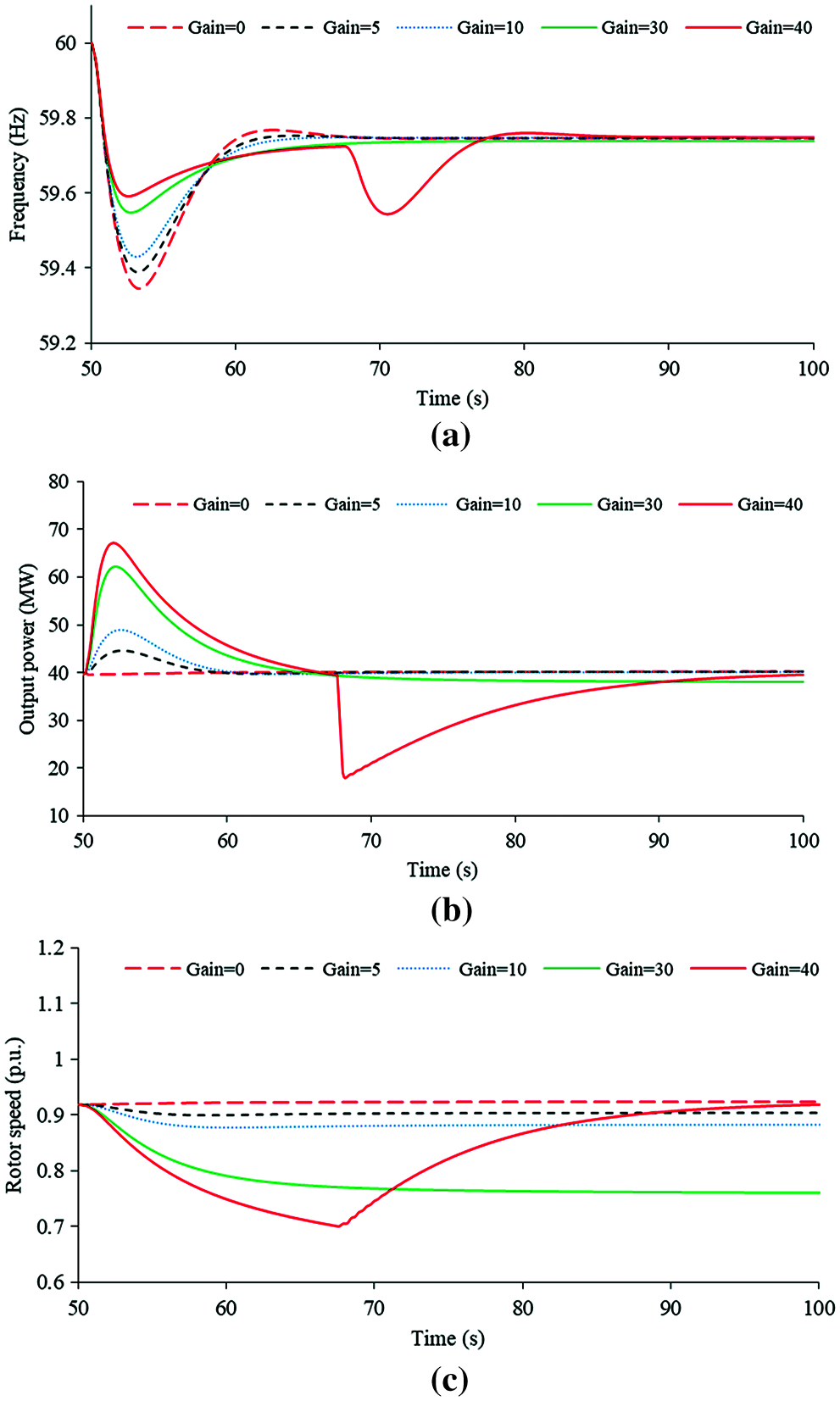
Figure 14: Simulation results of droop control strategy using various control coefficients under the wind speed of 8 m/s: (a) System frequencies; (b) Active powers; (c) Rotor speeds
4.2 Effects of the Disturbances and Control Strategies on Dynamic Frequency Response
The performance of dynamic frequency response is affected by a larger power output of the tripped generator, which results in a lower frequency nadir and large maximum df/dt. This subsection investigates the performance of inertia and droop control strategies when using various control coefficients for a case with the same wind condition as that in previous subsection, but a larger generator generating 110 MW is tripped out from the power grid.
4.2.1 Effects of the Inertia Control Strategy from a DFIG with the Wind Speeds of 8 and 10 m/s
The effects of inertia control strategy coefficient Kin on the dynamic frequency response with various wind speeds are showed in Figs. 15 and 16.
In the case of 10 m/s, increasing the control coefficient from 0 to 50, the frequency nadir is improved from 58.939 to 59.030 Hz; the maximum df/dt is reduced from −0.643 to −0.524 Hz/s. For 8 m/s, the frequency nadir is improved from 58.939 to 59.042 Hz; the maximum df/dt is reduced from −0.646 to −0.529 Hz/s, as shown in Figs. 15 and 16. The frequency nadir and maximum df/dt of 10 m/s are almost the same as those in 8 m/s. This is because the incremental powers of inertia control strategy with various wind conditions are almost the same. The basic observation is that even for a large disturbance, increasing the coefficient of inertia control strategy has a definitely positive influence on the dynamic frequency response including the frequency nadir and maximum df/dt.
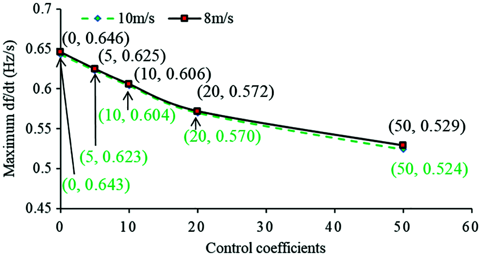
Figure 15: Absolute value of maximum df/dt with different inertia control coefficients

Figure 16: Frequency nadirs with different inertia control coefficients
4.2.2 Effects of the Droop Control Strategy from a DFIG with the Wind Speeds of 8 and 10 m/s
The influences of droop control strategy coefficient Kdr on the dynamic frequency response with various wind speeds are showed in Figs. 17 and 18.
As shown in Figs. 17 and 18, the control coefficient increases from 0 to 50, the maximum df/dt is reduced from −0.634 to −0.542 Hz/s for the case of 10 m/s and from −0.646 to −0.546 Hz/s for the case of 8 m/s. The first frequency nadir is increased from 58.939 to 59.226 Hz for the case of 10 m/s and from 58.939 to 59.342 Hz for the case of 8 m/s. Nevertheless, the second frequency nadir is caused when the coefficient is set to 50, which is 59.102 Hz for 10 m/s; the second frequency nadirs are caused when the coefficients are set to 40 and 50 for 8 m/s, which are 59.277 and 59.158 Hz, respectively. They are all lower than the first frequency nadir. The reason is that over-deceleration of the rotor speed is caused due to a large disturbance. In addition, the output power is limited by the torque limit referred to power so that the frequency nadir of 10 m/s is lower than that of 8 m/s when the control coefficients are set to 30, 40, and 50. The basic observation is that increasing the coefficient of droop control strategy has a definitely positive influence on the dynamic frequency response including the frequency nadir and maximum df/dt. However, increasing coefficient of inertia control beyond 30 cannot substantially contribute to the frequency nadir, even though it still improves the maximum df/dt for a low wind speed. Furthermore, as the control coefficient increases, the second frequency nadir becomes low. With the size of disturbance becomes large, more kinetic energy is released from the DFIG. The likelihood of causing second frequency nadir becomes larger and further deteriorating the frequency nadir, particularly for a low wind speed.
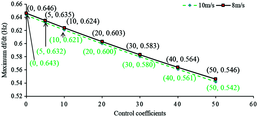
Figure 17: Absolute value of maximum df/dt with different inertia control coefficients
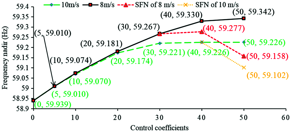
Figure 18: Frequency nadirs with different inertia control coefficients
The main objective of this research is to assess the influences of inertia and droop control coefficients on the dynamic frequency response with various wind conditions and disturbances. To this end, simulations with various wind conditions and disturbances using different control coefficient were performed.
Quantitative simulation results indicate that with the same control coefficient, the inertia control strategy is able to improve the maximum df/dt; whereas, the droop control strategy is able to improve the frequency nadir. For different disturbances and wind conditions, increasing the coefficients of the inertia control strategy and droop control strategy has a definitely positive influence on the dynamic frequency response including the frequency nadir and maximum df/dt. However, increasing the droop control coefficient beyond some point (which varies with different disturbances and wind conditions) does not substantially contribute to the frequency nadir, even though it still improves the maximum df/dt. For a low wind speed, the likelihood of causing a second frequency drop becomes large. For a high wind speed, the output power might be limited by the torque limit so that the contribution to improving the frequency nadir decreases.
A DFIG has a wide operating range compared to those of conventional synchronous generators. The available kinetic energies of a DFIG at 10 and 8 m/s are 1.62 and 2.67 s, respectively, which are 3.32 times and 5.48 times those of a synchronous generator with the same inertia constant that of a DFIG. Different wind conditions retain various available kinetic energies so that the control coefficients of inertia and droop control strategies should be set to different values. Hence, to utilize a DFIG to sufficiently support dynamic frequency response, a control coefficient that varies with the available kinetic energy and disturbance should be suggested.
Funding Statement: This work was supported by the Natural Science Foundation of the Jiangsu Higher Education Institutions of China (20KJB470026), and Key Project of Smart Grid Technology and Equipment of National Key Research and Development Plan of China (2016YFB0900601).
Conflicts of Interest: The authors declare that they have no conflicts of interest to report regarding the present study.
1. Ye, Y., Qiao, Y., Lu, Z. (2019). Revolution of frequency regulation in the converter-dominated power system. Renewable and Sustainable Energy Reviews, 111, 145–156. DOI 10.1016/j.rser.2019.04.066. [Google Scholar] [CrossRef]
2. Bao, W. Y., Ding, L., Liu, Z. F., Zhu, G. F., Kheshti, M. et al. (2020). Analytically derived fixed termination time for stepwise inertial control of wind turbines—Part I: Analytical derivation. International Journal of Electrical Power & Energy Systems, 121, 1–10. DOI 10.1016/j.ijepes.2020.106120. [Google Scholar] [CrossRef]
3. Yang, D. J., Kim, J., Kang, Y. C., Muljadi, E., Zhang, N. et al. (2018). Temporary frequency support of a DFIG for high wind power penetration. IEEE Transactions on Power Systems, 33(3), 3428–3437. DOI 10.1109/TPWRS.2018.2810841. [Google Scholar] [CrossRef]
4. Yang, D. J., Gao, H. C., Zhang, L., Zheng, T. Y., Hua, L. et al. (2020). Short-term frequency support of a doubly-fed induction generator based on an adaptive power reference function. International Journal of Electrical Power & Energy Systems, 119(1), 105955. DOI 10.1016/j.ijepes.2020.105955. [Google Scholar] [CrossRef]
5. Ackermann, T. (2012). Overview of integration studies-methodologies and results. In: Wind power in power system. England: John Wiley & Sons. [Google Scholar]
6. TransÉnergie, H. Q. (2009). Transmission provider technical requirements for the connection of power plants to the Hydro Québec transmission system. Revision February. https://www.hydroquebec.com/transenergie/fr/raccordement-reseau.html. [Google Scholar]
7. National Grid UK (2010). Grid code review panel paper, future frequency response services. https://www.nationalgrideso.com/codes/grid-code/meetings/grid-code-panel-29-august-2019. [Google Scholar]
8. Morren, J., Pierik, J., de Haan, S. W. (2006). Inertial response of variable speed wind turbines. Electric Power Systems Research, 76(11), 980–987. DOI 10.1016/j.epsr.2005.12.002. [Google Scholar] [CrossRef]
9. Ekanayake, J., Jenkins, N. (2004). Comparison of the response of doubly fed and fixed-speed induction generator wind turbines to changes in network frequency. IEEE Transactions on Energy Conversion, 19(4), 800–802. DOI 10.1109/TEC.2004.827712. [Google Scholar] [CrossRef]
10. Morren, J., Haan, S., Kling, L. W., Ferreira, J. A. (2006). Wind turbines emulating inertia and supporting primary frequency control. IEEE Transactions on Power Systems, 21(1), 433–434. DOI 10.1109/TPWRS.2005.861956. [Google Scholar] [CrossRef]
11. Lorenzo, Z., Andreas, J. R., Janus, M. S., Ioannis, M., Anca, D. H. et al. (2013). Virtual inertia for variable speed wind turbines. Wind Energy, 16, 1225–1239. DOI 10.1002/we.1549. [Google Scholar] [CrossRef]
12. Kayikci, M., Milanovic, J. V. (2009). Dynamic contribution of doubly-based wind plants to system frequency disturbances. IEEE Transactions on Power Systems, 24(22), 859–867. DOI 10.1109/TPWRS.2009.2016062. [Google Scholar] [CrossRef]
13. Tarnowski, G., Kjaer, P., Sørensen, P., Østergaard, J. (2009). Variable speed wind turbines capability for temporary over-production. IEEE Power & Energy Society General Meeting, pp. 1–7. Canada. DOI 10.1109/PES.2009.5275387. [Google Scholar] [CrossRef]
14. Xu, G., Xu, L., Morrow, D. J. (2012). Assessment and implementation of inertial response from variable speed wind turbines. Proceedings 11th International Workshop on Large-Scale Integration of Wind Power into Power Systems, Lisbon, Portugal. [Google Scholar]
15. Margaris, I. D., Papathanassiou, S. A., Hatziargyriou, N. D., Hansen, A. D., Sorensen, P. (2012). Frequency control in autonomous power systems with high wind power penetration. IEEE Transactions on Sustainable Energy, 3(2), 189–199. DOI 10.1109/TSTE.2011.2174660. [Google Scholar] [CrossRef]
16. Zhao, J. J., Lye, X., Fu, Y., Hu, X., Li, F. (2016). Coordinated microgrid frequency regulation based on DFIG variable coefficient using virtual inertia and primary frequency control. IEEE Transactions on Energy Conversion, 31(3), 833–845. DOI 10.1109/TEC.2016.2537539. [Google Scholar] [CrossRef]
17. Hu, Y. L., Wu, Y. K. (2019). Approximation to frequency control capability of a DFIG-based wind farm using a simple linear gain droop control. IEEE Transactions on Industry Applications, 55(3), 2300–2309. DOI 10.1109/TIA.2018.2886993. [Google Scholar] [CrossRef]
18. Byerly, R. T., Aanstad, O., Berry, D. H., Dunlop, R. D., Ewart, D. N. et al. (1973). Dynamic models for steam and hydro turbines in power system studies. IEEE Transactions on Power Apparatus and Systems, (6), 1904–1915. DOI 10.1109/TPAS.1973.293570. [Google Scholar] [CrossRef]
19. Yang, S. (2010). Novel sensorless generator control and grid fault ride-through strategies for variable-speed wind turbines and implementation on a new real-time simulation platform (Ph.D. Thesis). USA: Iowa State University. [Google Scholar]
20. Wang, Y., Delille, G., Bayem, H., Guilaud, X., Francois, B. (2013). High wind power penetration in isolated power systems—Assessment of wind inertial and primary frequency responses. IEEE Transactions on Power Systems, 28(3), 2412–2420. DOI 10.1109/TPWRS.2013.2240466. [Google Scholar] [CrossRef]
 | This work is licensed under a Creative Commons Attribution 4.0 International License, which permits unrestricted use, distribution, and reproduction in any medium, provided the original work is properly cited. |