| Energy Engineering |
DOI: 10.32604/ee.2022.016585
ARTICLE
A Dual Arm Complementary Hybrid Modulation Strategy Combining NL-SPWM for MMC Applications
1Key Laboratory of Smart Grid of Ministry of Education, Tianjin University, Tianjin, 300072, China
2Electric Power Research Institute of Yunnan Power Grid Co., Ltd., Kunming, 650217, China
*Corresponding Author: Yanbo Che. Email: lab538@163.com
Received: 26 March 2021; Accepted: 21 June 2021
Abstract: In the medium voltage direct current (MVDC) transmission system, a small number of MMC sub modules will reduce the power quality. In this paper, based on the research background of Photovoltaic Medium Voltage Direct Current (PV-MVDC) system, a Hybrid Modulation Strategy based on the Decoupled Double Synchronous Reference Frame (DDSRF) control strategy is proposed. The dual arm complementary hybrid modulation combining nearest-level-SPWM (NL-SPWM) can keep the number of SMs in the ON state constant. Then, the corresponding voltage sharing control algorithm of sub module (SM) is introduced. Through theoretical calculation, the modulation strategy can be found to stabilize the DC voltage and reduce the harmonic content. A 32-level MMC system has been developed to verity that the proposed hybrid modulation strategy and its SM voltage sharing algorithm have the advantages of restraining circulating current and maintaining capacitor voltage balance.
Keywords: Modular multilevel converter; modulation strategy; dual arm complementary; nearest-level-modulation; harmonics improvement
New energy power generation is one of the effective ways to solve the challenges of rapid growth of electricity demand and economic flexible operation of power grid. Photovoltaic modules can achieve the DC output, which is convenient for photovoltaic field access. Due to the dispersion of solar energy resources, it is a feasible solution for photovoltaic power generation to be connected to medium and high voltage power grid through distributed architecture [1]. A novel multilevel inverter is proposed in [2], which can not only reduce the number of switches and modular DC voltage sources, but also ensure a higher level at the output. However, it is not suitable for medium and high voltage DC transmission. Compared with the traditional two-level voltage source converter (VSC), the modular multilevel converter (MMC) has the advantages of scalability, flexibility, redundancy and low distortion [3]. MMC has become the preferred technology for medium and high voltage power grid, as it can realize the output of medium and high voltage through the series connection of SMs [4]. Besides, MMC topology have shown a superior performance during unbalanced PV power generation [5]. The large capacity distributed photovoltaic power station is connected to the medium and high voltage DC power grid, which helps to realize the economic operation of the system. However, for the MMC converter used in medium voltage direct current (MVDC) transmission system, the number of modules is small. If the common modulation strategy like nearest level modulation (NLM) is adopted, there will be obvious low-voltage harmonic and current distortion, which will reduce the power quality. Therefore, it is difficult to meet the actual operation requirements of photovoltaic medium and high voltage collection access system, which needs to be studied in depth.
Experts and scholars have studied the double frequency problem caused by power grid imbalance extensively and deeply. One of the solutions is using the control strategy of MMC in double decoupled synchronous coordinate system [6–11]. Based on this control strategy, a new hybrid modulation strategy is proposed in this paper.
Different modulation methods have important effects on the switching losses, capacitor voltage balance and voltage harmonic content of MMC. At present, two modulation strategies are commonly used in MMC, namely nearest level modulation (NLM) and carrier phase shift PWM (CPS-PWM). In [12–15], the implementation and operation principle of NLM are discussed in detail. For HVDC system with hundreds of modules in series, the ideal sinusoidal current can be obtained in MMC with NLM. However, for the MVDC transmission system below 10 kV, less number of single-phase arm series sub modules (SM) result in significant low-voltage harmonics. Although, NLM is simple to implement, it is mainly suitable for high-level converters and its applicability to MVDC system is limited. In [16–20], the basic operating principle of CPS-PWM was introduced. Beside this, the circulating current suppression strategy was also proposed. In research work [21], a fault-tolerant control strategy based on CPS-PWM is proposed. The redundant SMs is used to replace the faulty SMs to achieve fault-tolerant control of MMC. In [22], the authors proposed a flexible capacitor voltage control strategy based on CPS-PWM method. Although CPS-PWM method can reduce harmonics, the control becomes more complex because each SM is independently modulated [17]. Besides, the switching frequency IGBT in arms is high which results in high switching losses.
2 MMC Control Based on Decoupled Double Synchronous Coordinate System
The basic structure of 3-phase MMC is shown in Fig. 1. This structure utilizes the half bridge submodule design.
Under the stable working state, the three-phase AC voltage, DC voltage and arm voltage of MMC are symmetrical, so the mathematical model of MMC is illustrated by taking phase A as an example. The current value of upper and lower arms is
where, the line current at point O on the AC side is ioa; idiffa is the internal current of the converter flowing through the upper and lower arms at the same time, which is called the internal current of phase A.
According to KVL, the voltage of the upper and lower arms can be expressed as
Among them, upa and una represent the voltage of the upper and lower arms, respectively; ipa and ina are the current flowing through the upper and lower arms respectively; the voltage to ground is represented as uao; the equivalent inductance of the arm is expressed as L0.
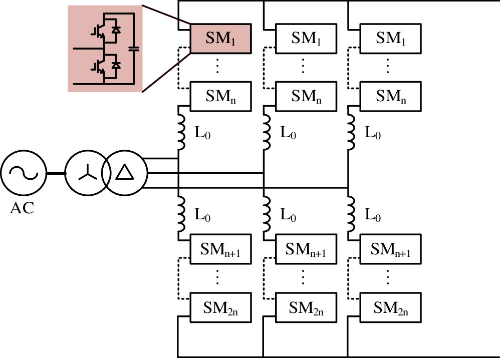
Figure 1: The topology of MMC
The internal electromotive force of phase A is
The internal unbalanced voltage drop of phase A is denoted as
It can be regarded as the voltage drop of idiffa on the series reactance of a arm, which is caused by the difference between the sum of voltage of upper and lower arms and DC voltage.
According to the switching status of IGBT in the upper and lower bridge arms of the sub module, the half bridge sub module (HBSM) can be divided into three working modes: BLOCK, ON and OFF. Combined with the current directions, it can be divided into six working states, as shown in Fig. 2.
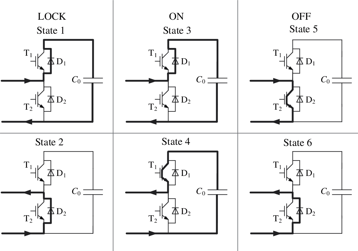
Figure 2: The working states of HBSM
In States 1 and 3, the voltage stresses of T1 and D1 are 0, that of T2 and D2 are −uc0. In States 2, 5 and 6, the voltage stresses of T1, T2, D1 and D2 are all 0. In State 4, the voltage stresses of T1 and D1 are 0, that of T2 and D2 are uc0.
2.2 MMC Control Strategy Based on Decoupled Double Synchronous Reference Frame
The general controller of MMC adopts double closed-loop control. The inner loop controller can quickly track the reference value of dq axis by adjusting the output voltage of the converter; and the outer loop controller can calculate dq axis current reference value of current controller according to DC voltage, active power and reactive power. MMC control in decoupled double synchronous reference frame (DDSRF) is adopted in this paper. The control block diagram is shown in Fig. 3.
The DDSRF can be used to decompose the instantaneous voltage and current into positive sequence component, negative sequence component and zero sequence component when the power grid is subjected to nonlinear load or transient fault. In dq coordinate system, the second harmonic component is eliminated by the component transformation difference between positive sequence and negative sequence, and the high-order harmonic component is eliminated by low-pass filter. Finally, the fundamental voltage wave is obtained.
The structure of phase locked loop (PLL) in DDSRF (DDSRF-PLL) is shown in Fig. 3a. By controlling the output value θ of PLL, the positive sequence component of q axis is zero to realize the phase-locked function. Since the second harmonic component cannot not be contained in the input signal of PLL, it can still be used in unbalanced state.
For the three-phase voltage and current, the abc component is transformed into dq coordinate system by T(θ) and T(−θ). The transformation of voltage and current is shown in Figs. 3b and 3c, respectively.
The inner loop controller adopts feedforward decoupling method to compensate voltage coupling. At the same time, considering the operating characteristics of the system under unbalanced conditions, the positive sequence component and negative sequence component of voltage and current are separated. Because the zero sequence component is blocked by Δ − Y transformer, there are only positive and negative sequence components. Therefore, the positive sequence and negative sequence current controllers with PI regulation are shown in Figs. 3d and 3e. By setting the negative sequence current command to 0, the negative sequence current value of MMC side can be suppressed and the current overload of power devices can be avoided.
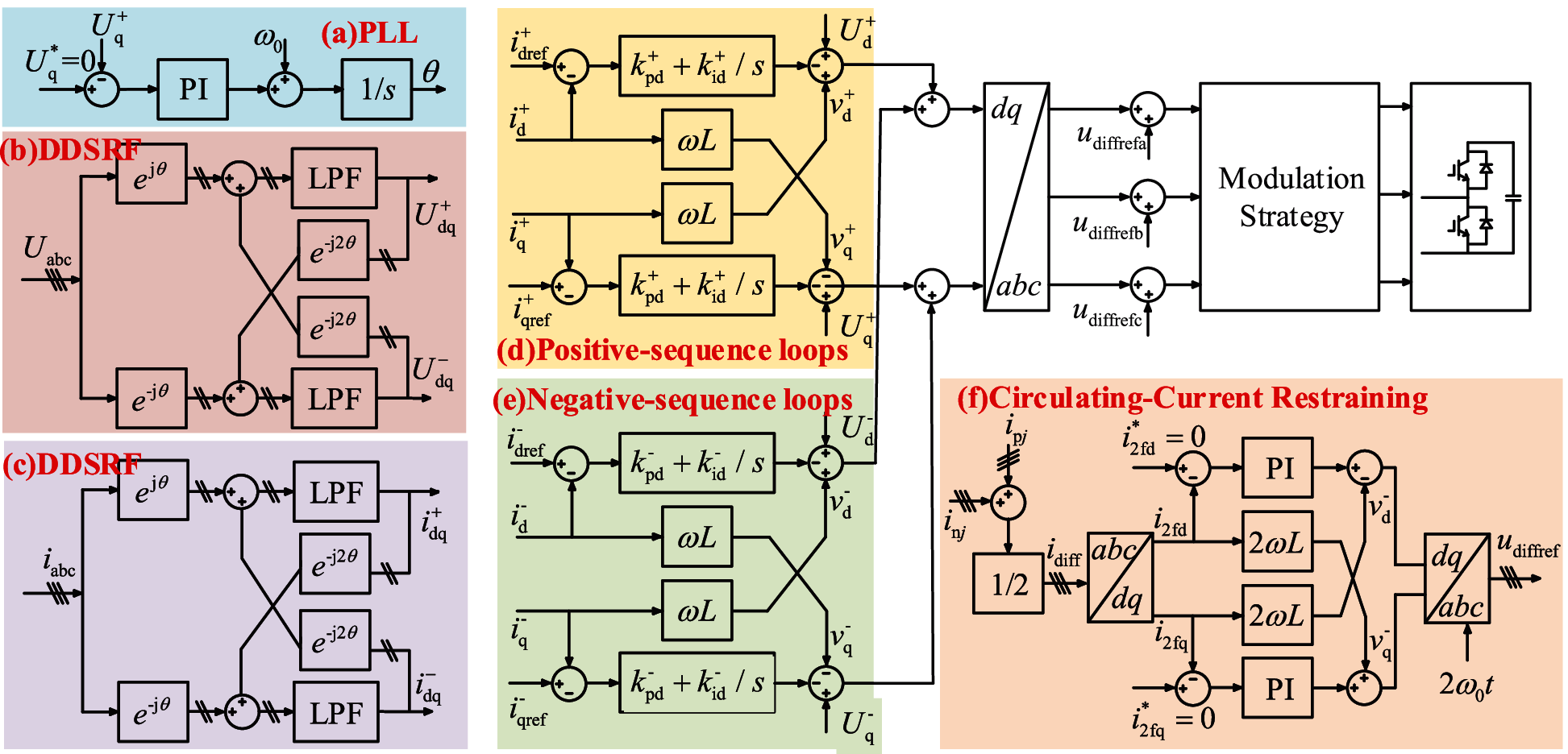
Figure 3: Control block diagram of MMC
The circulating current exists in the MMC converter, which is independent of the external power supply and load. The existence of circulating current will lead to the distortion of arm current. Hence, it is necessary to restrain the circulating current. The three-phase circulating current flows in the phase sequence of A–C–B between MMC phase units, presenting double frequency negative sequence characteristics. By using the transformation formula and bringing θ = 2ω into the transformation matrix, the circulation can be separated into two direct flows in a rotating coordinate system, as shown in Fig. 3f.
In this paper, a constant DC voltage outer loop controller is adopted. The DC bus voltage and current are Udc and Idc, respectively. Ignoring the network loss, line loss, device loss and other losses, the active power of photovoltaic input DC side and grid connected output AC side should be equal, according to the law of conservation of energy.
Then the d-axis current component is
The expression of outer loop voltage controller is deduced as follows:
The block diagram of constant DC voltage outer loop controller is shown in Fig. 4.
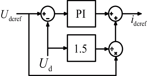
Figure 4: Outer loop controller of constant DC voltage
3 NL-SPWM Combining Dual Arm Complementary Strategy
Fig. 5 shows the block diagram of NL-SPWM combining dual arm complementary strategy proposed in this paper.
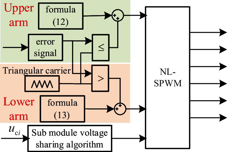
Figure 5: Control block diagram of NL-SPWM combining dual arm complementary strategy
3.1 Traditional MMC Modulation Strategy
The control of MMC usually adopts NLM or CPS-PWM. The two modulation strategies are briefly introduced below.
Compared with the traditional high-frequency PWM modulation strategy, the NLM strategy has some advantages in waveform quality, switching loss, control mode and capacitor voltage equalization. The basic principle of NLM is to make the output voltage waveform as close to the sine wave as possible by controlling the number of SMs in the on and off state.
The phase voltage and arm voltage output by using NLM strategy can be expressed as
The number of upper and lower arms in SMs can be calculated by formula (2) and formula (8)–(10) as follows:
where N is the number of SMs in the arms; Npi and Nni represent the number of ON state SMs in the upper and lower arms, respectively. round (x) is the nearest integer function; uoi is the reference voltage of phase i and Uc is the capacitance voltage of SMs.
The basic principle of CPS-PWM strategy can be expressed as comparing N triangular carrier signals in the same frequency, same peak value but 360°/N phase interval with the same sinusoidal modulation signal. The N-channel independent PWM pulse signals are distributed to the power switch devices of N SMs in the arms, and the SMs can be switched independently at any time. This method is suitable for high switching frequency application scenarios.
In the medium and low voltage applications, the step wave generated by the NLM strategy will produce some error signals in the process of approaching the sinusoidal modulation signal. Especially when the number of levels is small, the error is large. The output phase voltage will contain large low order harmonic components, and the distortion rate of output phase current is high. When the CPS-PWM strategy is used, the harmonic content will be lower than the NLM strategy, but the switching frequency of power devices is too high, the switching loss is too large, and the control is complex. Based on the NLM strategy, hybrid modulation strategy (NL-SPWM) adopts the principle of CPS-PWM to remodulate the error signal generated by the NLM strategy. On the premise of ensuring the quality of output voltage waveform, the conversion efficiency of MMC is improved, and the switching loss and total harmonic distortion rate of phase current are reduced.
First of all, the hybrid modulation strategy uses the basic idea of the NLM and the principle of rounding down to generate a group of step waves approaching the modulated signal. The number of SMs that should be put into each phase arm is as follows:
At this time, the total number of SMs put into operation at any time is N − 1.
Secondly, the error signal between the stepped wave and the sinusoidal modulation signal in the downward NLM process is collected. It is regarded as the modulation signal on each step of the step wave. CPS-PWM is used for modulation. In order to reduce the switching frequency as much as possible, only one SM is selected for CPS-PWM modulation. The principle is shown in Fig. 6.
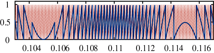
Figure 6: Schematic diagram of NL-SPWM
Finally, this group of CPS-PWM signals are superimposed on the stepped wave generated by the downward NLM to form the SM switch control signal of hybrid modulation strategy. The generation process of mixed modulation pulse signal is shown in Fig. 7.
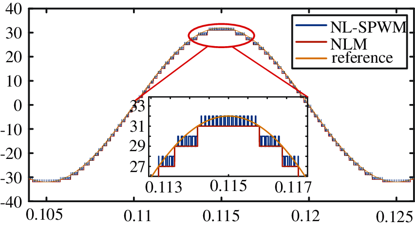
Figure 7: Comparison of output waveforms
In the hybrid modulation strategy, only one SM works in SPWM mode at any time, and the other N − 1 SMs are switched in the form of step wave. Compared with the modulation process of the NLM strategy, the triangular carrier signal is used to remodulate the error signal generated by the downward approaching sinusoidal modulation signal, which improves the modulation accuracy of the modulation strategy.
3.3 Dual Arm Complementary Hybrid Modulation Strategy Combining NL-SPWM
As the number of SMs in ON state is N − 1 after the NLM, it does not meet the requirement that the number of on SMs of upper and lower arms is N. In this paper, the upper and lower arms use the same triangular carrier signal and choose the opposite ON and OFF states for modulation, so as to ensure that the upper and lower arms are completely complementary. Thus, the input number of SMs is always N.
Suppose the carrier signal is utri and the error signal is uΔ. Then the control signal of the upper and lower arms can be expressed as
The DC bus voltage can be calculated as
Therefore, the NL-SPWM method can ensure the dc voltage of the MMC to remain at NUc in any instance. As long as the voltage balancing for each SM is realized, the arm circulating current can be reduced as well.
The specific principle is shown in Fig. 8.
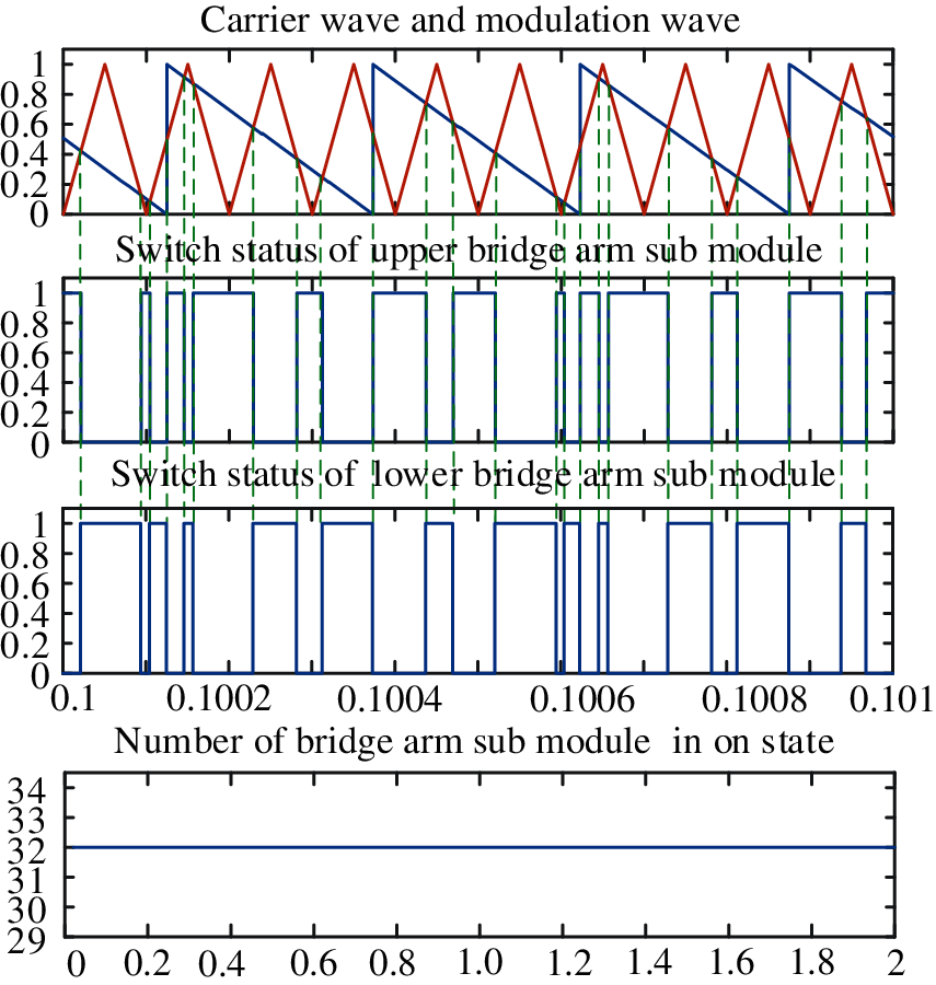
Figure 8: Complementary schematic diagram of upper and lower arms
It can be seen from Eq. (12) that when the downward NLM method is adopted, at most 31 SMs of the upper arm are turned on. Then, the operation mode of the 32nd SM is determined according to the relationship between the error signal and triangle carrier as shown in Eqs. (13), (14). At the same time, the corresponding 32nd SM of the lower arm adopts complementary control signal to make the output voltage as close to the voltage reference value as possible. The operation modes of the lower arms are opposite to that of the upper arms.
3.4 Capacitor Voltage Equalization of SMs
The traditional sorting algorithm has better control effect for the NLM strategy with low switching frequency [13]. In the hybrid modulation strategy, a SM works in CPS-PWM mode and its overall switching frequency is slightly higher than the nearest level modulation strategy. Therefore, in order to reduce the switching frequency of the SM of hybrid modulation strategy, this paper designed an improved SM voltage sharing control algorithm based on the traditional sorting algorithm.
Firstly, when the level number changes, according to the principle of the nearest level approximation and the principle of rounding down, the sum of the number of SMs that should be put into each phase arm is calculated as N − 1.
Secondly, according to the current direction of each phase arm, the working state of the SM is judged. When the SMs work in the charging mode, the capacitor voltage values of the arm SMs are sorted from small to large, and the SMs with lower capacitance voltage are put in priority. When the SMs work in the discharge mode, the capacitor voltage values of the arm SMs are sorted from large to small, and the SMs with higher capacitance voltage are put in priority.
Finally, the second to the N SMs are switched normally. The modulation signal of the first SM adopts the method proposed in 3.3, that is, the error signal between step wave and sinusoidal modulation signal produced by downward approximation is compared with the triangular carrier signal, and the working state of the SM is givenThe improved SM voltage sharing control flow is shown in Fig. 9.
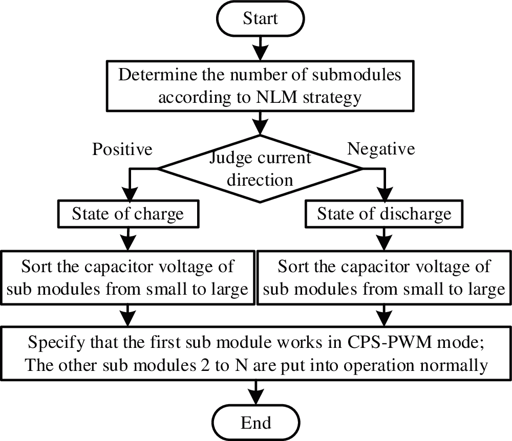
Figure 9: Generation process of SM capacitor voltage equalization
The improved voltage sharing control algorithm of SMs has a feature: when the SMs work in charging mode, the control algorithm puts the SM with the smallest capacitance voltage of arms in the CPS-PWM mode; when the SMs works in the discharge mode, the control algorithm puts the SM with the largest capacitance voltage value of arms in the CPS-PWM mode. This arrangement can ensure that the output voltage of each phase is stable at any time to the greatest extent. Only one SM works in CPS-PWM mode, which reduces the switching frequency of hybrid modulation strategy and the switching loss of MMC system to a certain extent. It not only realizes the voltage balance of the SMs, but also suppresses the circulating current of the arms.
3.5 Harmonic Analysis of the MMC with NL-SPWM
The capacitor voltages of the SMs are assumed to be balanced and constant in the following harmonic analysis. According to the principle of NL-SPWM, the output multilevel PWM waveform of the MMC can be regarded as the superposition of a N − 1 level staircase wave and a two-level PWM wave.
Therefore, the harmonic analysis of uni is carried out with unlm and uPWM separately.
According to the double Fourier transform, the PWM wave can be expressed as
where y = ωrt and x = ωct, ωr and ωc are the angular frequencies of the reference wave and carrier wave, respectively.
To obtain analytical expressions for the harmonics, the valid ntegral interval for x and y should be determined first, and then the amplitude of harmonics can be calculated by (18).
The reference wave of the PWM module in the lower arm, namely ur, which can be divided into 2N segments. The switching instants are ± y0,…, ± yk,…, ± yN, where y0 = π, yN = 0, and segment number k is the number of SMs in ON state. The per-unit reference wave of segment ± k can be expressed as
The switching instant yk can be calculated by
According to (17)–(20), uPWM can be derived as
where
where <M> represents the smallest integer greater than M and Jn(x) is the n-order Bessel function.
The Fourier series of the staircase wave in the lower arm is derived as
Substituting (21) and (22) to (16), the output voltage of the lower arm is expressed as
For the N + 1 level modulation, the phase voltage has the same frequency spectrum with the lower arm voltage waveform except the dc component, which is expressed as
Likewise, the output voltage of phase B can be derived as
Then, the Fourier series of the line voltage uab is given as
The main harmonic components of the phase voltage with different N while fc = 2000 Hz and fr = 50 Hz are calculated according to above harmonic analytical expressions and shown in Fig. 9. The harmonic characteristics of the NL-SPWM are summarized as follows:
1. The second harmonic is effectively suppressed and there is no low-order harmonics. The phase voltage contains odd carrier frequency harmonics, sideband harmonics near carrier frequency. The line voltage does not contain the harmonics of mωc (m = 1, 2, 3,…).
2. As seen in Fig. 10, the harmonic of ωc is the most prominent harmonic component in the phase voltage spectrum, and the other harmonics are all less than 2% even with N = 6. As the line voltage has no ωc harmonic, its total harmonic distortions (THD) stays small even for the MMC with very few modules.
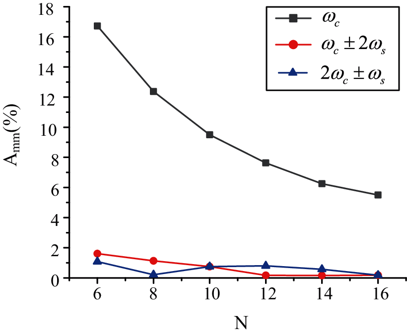
Figure 10: Main harmonic components of the phase voltage by NL-SPWM with different N
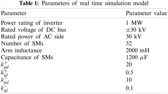
In MATLAB/Simulink, the MMC system with 32 half bridge SM is built by using NLM and NL-SPWM modulation methods, respectively. Since neutral point grounding is set at the DC bus, the DC bus voltage rating is ±30 KV. The MMC parameters are shown in Table 1.
The input phase current of MMC network side is analyzed. Under NLM and NL-SPWM modulation, the simulation results of MMC output phase current are shown in Fig. 11a; the voltage of arm on phase A are shown in Fig. 11b; DC side output voltage of MMC is shown in Fig. 11c. Taking the A-phase upper arm as an example, the fluctuation of capacitor voltage of SMs in the charging and discharging process of the two modulation strategies are shown in Fig. 11d. Fourier analysis is used to analyze the phase current simulation results of the nearest level modulation strategy and the hybrid modulation strategy, respectively. The analysis results of the nearest level modulation strategy are shown in Fig. 11e.
As shown in Fig. 11a, it can be seen from the comparison that the waveform quality of the phase current under the NLM strategy is poor, the distortion is serious, and there are many burrs. Under the mixed modulation strategy, the input phase current waveform of MMC is smoother and closer to sine wave. The phase voltage of the two modulation strategies achieves phase synchronization.
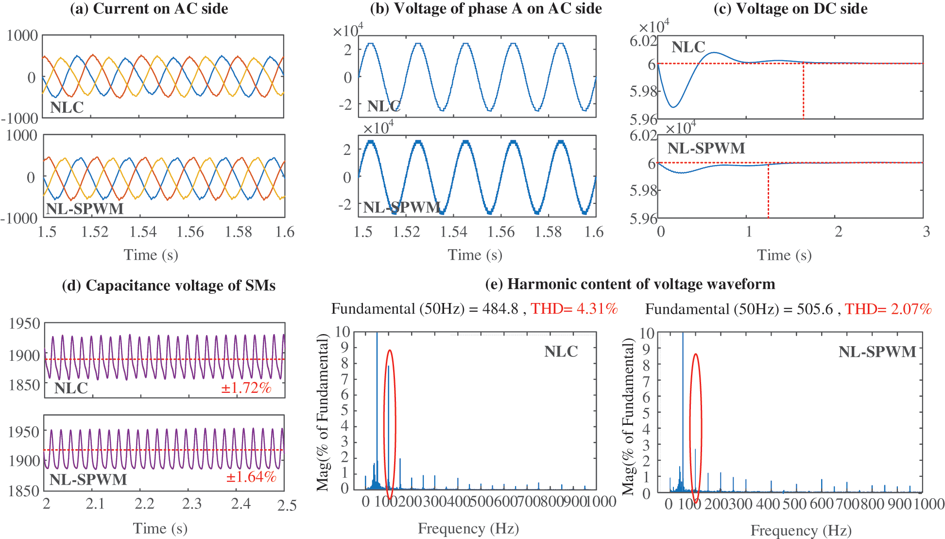
Figure 11: Output waveform comparison between NLM and NL-SPWM
As shown in Fig. 11b, when the voltage of the upper arm of phase a under NL-SPWM is locally amplified, it can be observed that the voltage of the upper arm under the mixed modulation is composed of multiple fine step waves, which is closer to the sine wave in effect.
It can be seen from Fig. 11c that the DC side output voltage with NLM strategy has overshoot and large fluctuation, while the DC side output voltage with NL-SPWM is more stable and the overshoot is significantly smaller.
Compared with Fig. 11d, it can be seen that under the NLM, the capacitor voltage of SMs fluctuates up and down in 1887 V, with the fluctuation range of ±1.72%; while under the mixed modulation strategy, the capacitor voltage of SMs fluctuates up and down in 1918 V with the fluctuation amplitude within ±1.64%. It can be concluded that in steady-state operation, the capacitor voltage of the SMs under the two modulation strategies are better, but the voltage fluctuation of the SMs in the hybrid modulation strategy with the improved voltage sharing control algorithm is smaller.
From Fig. 11e, the total harmonic distortion (THD) rate of MMC input phase current under the NLM strategy is 4.31%, and that of MMC input phase current under hybrid modulation strategy is 2.07%. Under the two modulation strategies, the total harmonic distortion rates of MMC input phase voltage are all well controlled, but the total harmonic distortion rate of input phase current and phase voltage under hybrid modulation strategy is lower than that of the NLM strategy. At the same time, compared with the NLM, it can be seen that the second harmonic of the proposed modulation strategy is significantly reduced. Therefore, according to the simulation results of MMC input phase current, the mixed modulation strategy has better modulation effect on MMC.
In this paper, a 32 level MMC topology is built for application in PV-MVDC System. Then, MMC control strategy based on DDSRF is established. As a dual arm complementary hybrid modulation strategy based on NL-SPWM is designed, the number of SMs input by upper and lower arms are guaranteed to be constant. The corresponding voltage sharing control algorithm is proposed subsequently. Finally, the superiority of the proposed strategy is verified by simulation.
The dual arm complementary hybrid modulation strategy inherits the advantages of the NLM. Without additional control for each SM, the voltage balance can be achieved by sorting the SMs according to their voltage, which simplifies the control system. Different from CPS-PWM, NL-SPWM reduces the nonlinear harmonics caused by different SMs voltages. As one SM operates in PWM mode, the system switching frequency will be slightly higher than the NLM strategy, but the overall switching frequency of the SMs is far lower than that of CPS-PWM strategy.
The proposed modulation strategy and its voltage sharing algorithm can not only ensure the stability of DC output voltage, but also achieve good voltage sharing effect. Besides, the second harmonic and harmonic distortion rate are significantly reduced.
Funding Statement: This work was supported by the National Key Research and Development Project of China (2018YFB0905803).
Conflicts of Interest: The authors declare that they have no conflicts of interest to report regarding the present study.
1. Iddique, H., Doncker, R. (2018). Evaluation of DC collector-grid configurations for large photovoltaic parks. IEEE Transactions of Power Delivery, 33(1), 311–320. DOI 10.1109/TPWRD.2017.2702018. [Google Scholar] [CrossRef]
2. Siddique, M. D., Mekhilef, S., Shah, N. M., Memon, M. A. (2019). Optimal design of a new cascaded multilevel inverter topology with reduced switch count. IEEE Access, 7, 24498–24510. DOI 10.1109/ACCESS.2019.2890872. [Google Scholar] [CrossRef]
3. Debnath, S., Qin, J., Bahrani, B., Saeedifard, M., Barbosa, P. (2019). Operation, control, and applications of the modular multilevel converter: A review. IEEE Transactions on Power Electronics, 30(1), 37–53. DOI 10.1109/TPEL.2014.2309937. [Google Scholar] [CrossRef]
4. Yi, W., Hu, C., Ding, R., Xu, L., Chao, F. et al. (2018). A nearest level PWM method for the MMC in DC distribution grids. IEEE Transactions on Power Electronics, 3(11), 9209–9218. DOI 10.1109/TPEL.2018.2792148. [Google Scholar] [CrossRef]
5. Elsanabary, A. I., Konstantinou, G., Mekhilef, S., Townsend, C. D., Stojcevski, A. (2020). Medium voltage large-scale grid-connected photovoltaic systems using cascaded H-bridge and modular multilevel converters: A review. IEEE Access, 8, 223686–223699. DOI 10.1109/ACCESS.2020.3044882. [Google Scholar] [CrossRef]
6. Moon, J. W., Park, J. W., Kang, D. W. (2015). A control method of HVDC-modular multilevel converter based on arm current under the unbalanced voltage condition. IEEE Transactions on Power Delivery, 30(2), 529–536. DOI 10.1109/TPWRD.2014.2342229. [Google Scholar] [CrossRef]
7. Che, Y., Lv, Z., Zhu, J., Zhou, J., Jia, J. et al. (2020). Automatic-coordinated transitioning control scheme for PV-MVDC system under grid unbalanced conditions. International Journal of Electrical Power & Energy Systems, 119(3), 105896. DOI 10.1016/j.ijepes.2020.105896. [Google Scholar] [CrossRef]
8. Miret, J., Castilla, M., Camacho, A., Vicuña, L. G. D., Matas, J. (2012). Control scheme for photovoltaic three-phase inverters to minimize peak currents during unbalanced grid-voltage sags. IEEE Transactions on Power Electronics, 27(10), 4262–4271. DOI 10.1109/TPEL.2012.2191306. [Google Scholar] [CrossRef]
9. Roscoe, A. J., Finney, S. J., Burt, G. M. (2011). Tradeoffs between AC power quality and dc bus ripple for 3-phase 3-wire inverter-connected devices within microgrids. IEEE Transactions on Power Electronics, 26(3), 674–688. DOI 10.1109/TPEL.2011.2105892. [Google Scholar] [CrossRef]
10. Yazdani, A., Iravani, R. (2016). A unified dynamic model and control for the voltage-sourced converter under unbalanced grid conditions. IEEE Transactions Power Delivery, 21(3), 1620–1629. DOI 10.1109/TPWRD.2006.874641. [Google Scholar] [CrossRef]
11. Moon, J., Park, J., Kang, D., Kim, J. (2015). A control method of HVDC-modular multilevel converter based on arm current under the unbalanced voltage condition. IEEE Transactions Power Delivery, 30(2), 529–536. DOI 10.1109/TPWRD.2014.2342229. [Google Scholar] [CrossRef]
12. Hu, P., Jiang, D. (2015). A level-increased nearest level modulation method for modular multilevel converters. IEEE Transactions on Power Electronics, 30(4), 1836–1842. DOI 10.1109/TPEL.2014.2325875. [Google Scholar] [CrossRef]
13. Deng, Y., Saeedifard, M., Harley, R. G. (2015). An improved nearest-level modulation method for the modular multilevel converter. IEEE Applied Power Electronics Conference and Exposition, pp. 1595–1600. Charlotte, NC. [Google Scholar]
14. Lin, L., Lin, Y., He, Z., Chen, Y., Hu, J. et al. (2016). Improved nearest-level modulation for a modular multilevel converter with a lower submodule number. IEEE Transactions on Power Electronics, 31(8), 5369–5377. DOI 10.1109/TPEL.2016.2521059. [Google Scholar] [CrossRef]
15. Mei, M., Wang, P., Che, Y. (2021). Adaptive coordinated control strategy for multi-terminal flexible DC transmission systems with deviation control. Journal of Power Electronics, 21(4), 724–734. DOI 10.1007/s43236-021-00219-7. [Google Scholar] [CrossRef]
16. Ji, M., Wang, Y., Hu, C. (2019). A novel modulation method for the mmc applied to medium voltage distribution grids. 45th Annual Conference of the IEEE Industrial Electronics Society, Lisbon, Portugal. [Google Scholar]
17. Lei, L., Lin, Y., Zhen, H., Yu, C., Hu, J. et al. (2016). Improved nearest-level modulation for a modular multilevel converter with a lower submodule number. IEEE Transactions on Power Electronics, 31(8), 5369–5377. DOI 10.1109/TPEL.2016.2521059. [Google Scholar] [CrossRef]
18. Deng, F., Chen, Z. (2014). A control method for voltage balancing in modular multilevel converters. IEEE Transactions on Power Electronics, 29(1), 66–76. DOI 10.1109/TPEL.2013.2251426. [Google Scholar] [CrossRef]
19. Zhang, M., Huang, L., Yao, W., Lu, Z. (2014). Circulating harmonic current elimination of a CPS-PWM-based modular multilevel converter with aplug-in repetitive controller. IEEE Transactions on Power Electronics, 29(4), 2083–2097. DOI 10.1109/TPEL.2013.2269140. [Google Scholar] [CrossRef]
20. Lu, S., Yuan, L., Li, K., Zhao, Z. (2017). An improved phase-shifted carrier modulation scheme for a hybrid modular multilevel converter. IEEE Transactions on Power Electronics, 32(1), 81–97. DOI 10.1109/TPEL.2016.2532386. [Google Scholar] [CrossRef]
21. Li, K., Yuan, L., Zhao, Z., Lu, S., Zhang, Y. (2017). Fault-tolerant control of MMC with hot reserved submodules based on carrier phase shift modulation. IEEE Transactions on Power Electronics, 32(9), 6778–6791. DOI 10.1109/TPEL.2016.2628762. [Google Scholar] [CrossRef]
22. Tai, B., Gao, C., Liu, X., Chen, Z. (2017). A novel flexible capacitor voltage control strategy for variable-speed drives with modular multilevel converters. IEEE Transactions on Power Electronics, 32(1), 128–141. DOI 10.1109/TPEL.2016.2535463. [Google Scholar] [CrossRef]
 | This work is licensed under a Creative Commons Attribution 4.0 International License, which permits unrestricted use, distribution, and reproduction in any medium, provided the original work is properly cited. |