| Energy Engineering |
DOI: 10.32604/ee.2022.016661
ARTICLE
Analysis of Power Quality Problems in Large-Scale Application of Air-Source Heat Pump
1Key Laboratory of Smart Grid of Education Ministry, Tianjin University, Tianjin, 300072, China
2Electric Power Science Research Institute of State Grid Jiangxi Electric Power Co., Ltd., Nanchang, 330096, China
*Corresponding Author: Yanbo Che. Email: lab538@163.com
Received: 15 March 2021; Accepted: 15 June 2021
Abstract: With the implementation of electric energy alternatives, the large-scale application of electric energy substitution represented by air-source heat pumps has replaced traditional coal-fired heating, which is beneficial for the environment and alleviates air pollution. However, the large-scale application of air-source heat pumps has brought power quality problems such as voltage sags, harmonic pollution, and three-phase imbalance to the distribution network. This paper studies the fixed-frequency and variable-frequency air-source heat pump, introduces its working principle, analyzes the mechanism of its power quality problem. Moreover, the paper establishes a simulation model for the fixed-frequency heat pump and variable-frequency heat pump to connect to the distribution network. This research mainly studies the impact of large-scale fixed-frequency heat pumps on the depth of voltage sags in the distribution network and the impact of large-scale variable-frequency heat pumps on the harmonic content of the distribution network under different penetration rates and uses measured data to verify the reliability of the simulation results. This paper uses experimental data for the first time to verify the real power quality problems of large-scale heat pumps, which can provide a reference for determining the power quality standards for heat pumps connected to the power grid. At the same time, it can also provide a reference for the power quality management of the distribution network that is actually connected to electric heating.
Keywords: Air-source heat pump; voltage sag; harmonic; penetration rate
In order to solve the problem of urban smog, the State Grid Corporation of China issued a power substitution implementation plan on 15 August, 2013. The plan proposes to vigorously advocate the new concept of energy consumption of “substituting electricity for coal, using electricity for oil, and electricity from afar” and fully initiate the work of electric energy substitution in the company’s business area [1]. At present, the large-scale application of electric energy substitution technology represented by electric heating plays a vital role in optimizing Chinese energy structure and controlling environmental pollution.
After implementing electric energy substitution, heating equipment based on air-source heat pumps has been applied to rural distribution networks on a large scale via low energy consumption and high efficiency. Beijing has carried out a pilot promotion of air-source heat pumps since 2015. From 2016, following the requirements of the State Council and the Ministry of Environmental Protection, entire large-scale villages have been promoted “coal-to-clean energy” to achieve the goal of “no coal” in villages in the southern seven districts and plains in 2017 [2].
When a large-scale air-source heat pump is connected to the distribution network, the power quality problem of the distribution network becomes more and more serious. When the heating season arrives, low voltages appear in the electric energy replacement area, and even three-phase imbalance and other problems occur. Due to these problems, grid planning, power dispatching, and benefits evaluation after the large-scale integration of heat pumps cannot be carried out. Therefore, it is necessary to study the power quality problems after the large-scale application of air-source heat pumps to solve the power problems in this scenario.
The literature in [3] analyzed the performance of the heat pumps with different refrigerants and vapor injection methods to select the suitable configuration. The study reported that using an economizer has a more significant impact on the GSHP cycle. The research in [4] investigated the impact of various refrigerants on the efficiency of the geothermal heat pump operation and concludes that R134A and R125 refrigerants have the highest and lowest COP and exergy efficiency, respectively. The authors in [5] investigated the two-phase flow boiling heat transfer characteristics of a refrigerant. The optimization of the energy cost value and efficiency of the energy system through thermodynamic analysis is performed in [6]. The literature in [7] uses thermo-economic analysis to achieve the best cycle from a thermodynamic and economic perspective. The research in [8] performs ANNs modeling to predict pressure drop in two-phase flow in long horizontal pipes for a wide range of operating conditions considering the pipe diameters and fluid characteristics. In most cases, the deviation of the predicted pressure drop from the experimental data does not exceed 5%. The above-mentioned literature mainly focuses on advanced technologies that can improve the performance of the passive and active systems of heat pumps. The analysis of the harmonic effects of various types of electric heating equipment in the low-voltage distribution network is performed in [9]. Literature in [10] uses the actual load data to construct a simulation model of the power consumption of the typical electric heating load. It analyzes the influence of multiple electric heating equipment on the harmonics and voltage sag of the distribution network. The study in [11] simulated the voltage drop and harmonics caused by the large-scale heat pump access to the low-voltage distribution network and analyzed the different effects of different heat pumps. Although the above papers have analyzed the power quality problems of multiple or large-scale heat pumps, they have not analyzed the power quality problems of each phase, nor have they considered power quality problems such as three-phase imbalance. This paper starts from the mechanism of the power quality problem generated by the heat pump and combines it with the distribution network implemented by the actual electric energy alternative scheme. Subsequently, a simulation model of the large-scale heat pump access to the distribution network is established. The power quality problems of each phase generated by large-scale fixed-frequency and variable-frequency heat pumps are analyzed, respectively. Finally, the reliability of the simulation results is verified according to the measured data.
2 The mechanism of Air-Source Heat Pump Power Quality Problem
Air-source heat pumps are classified into fixed-frequency air-source heat pumps and variable-frequency air-source heat pumps according to whether the frequency changes during operation. This article takes the fixed-frequency and variable-frequency air-source heat pump as the research objective. Later, the paper introduces its working principle and analyzes its power quality emission characteristics.
2.1 Brief Introduction of Air-Source Heat Pump
The air-source heat pump system is based on the principle of reverse Carnot cycle and is mainly composed of a compressor, an evaporator, a condenser, and an expansion valve. Its working principle is shown in Fig. 1.
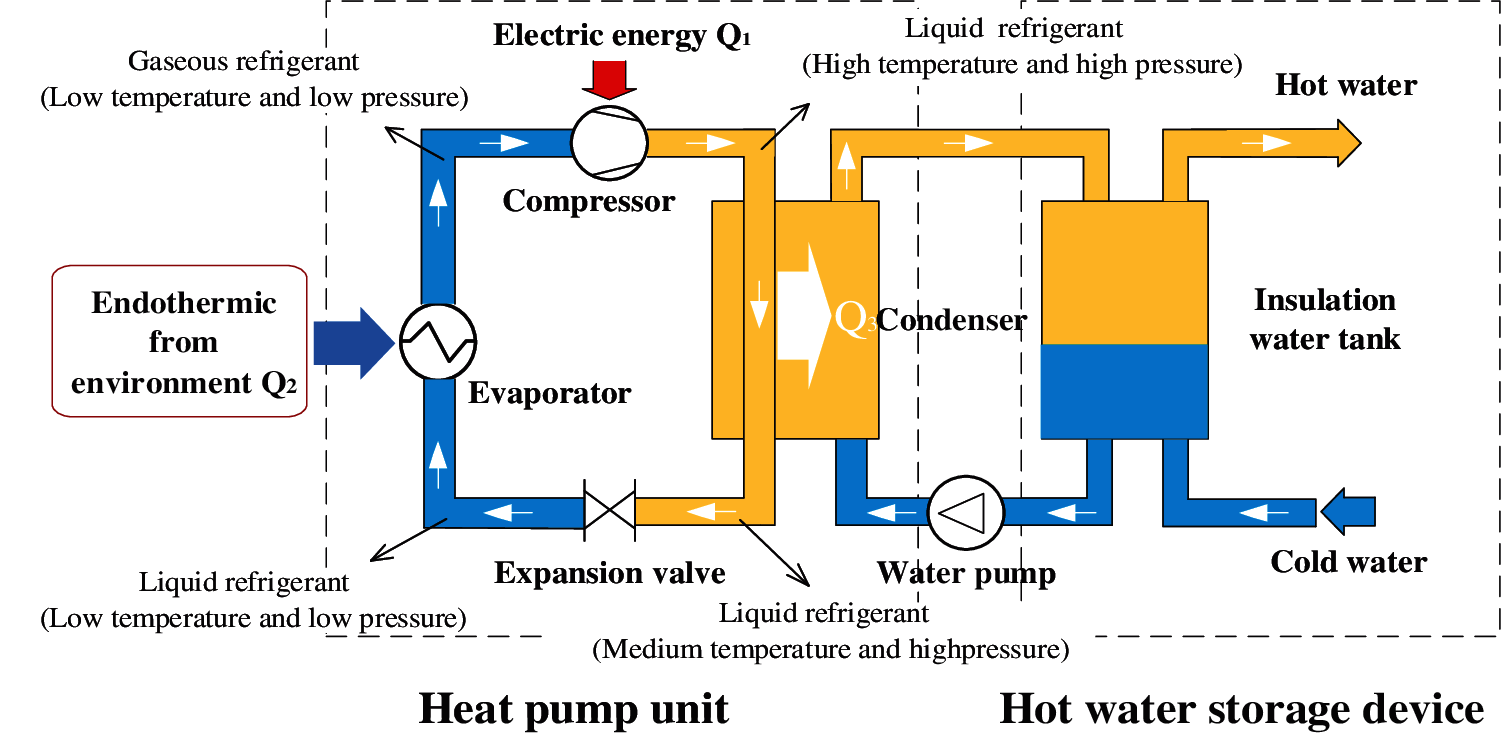
Figure 1: Working principle of air-source heat pump
First, the low-temperature (−32–40°C) and low-pressure liquid refrigerant passes through the evaporator to absorb the heat Q2 in the air and changes from a liquid state to a low-temperature (5–40°C) and low-pressure gaseous refrigerant. The compressor converts low-temperature and low-pressure gaseous refrigerant into high-pressure, high-temperature (80–100°C) gas, and the heat converted by the compressor’s compression function is Q1. The high-temperature and high-pressure liquid refrigerant exchanges heat with water to become a medium-temperature (40–60°C) and high-pressure liquid. In this process, the refrigerant emits heat (Q3 = Q1 + Q2) to heat the water, and the hot water is placed in the water storage device. The high-pressure liquid refrigerant is decompressed through the expansion valve back to a low-temperature and low-pressure state and then enters the evaporator again to recirculate the process. Air-source uses high-level energy to make heat flow from low-level heat source air to a high-level heat source. The air-source heat pump can convert the unusable low-level heat energy (such as the heat in the air, soil, water) into usable high-level heat energy to save part of the high-level energy (such as coal, gas, oil, electricity, etc.).Therefore, it has low energy consumption, high efficiency, high speed, good safety, strong environmental protection, and can continuously supply hot water.
2.2 Power Quality Emission Characteristics
2.2.1 Fixed-Frequency Air-Source Heat Pump
The compressor determines the operating performance of the fixed-frequency air-source heat pump, which can be equivalent to a single-phase asynchronous motor [12], as shown in Fig. 2.
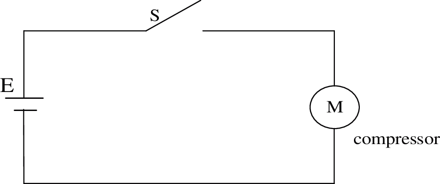
Figure 2: Fixed-frequency heat pump equivalent topology
The authors in [13] study the voltage sag problem when the fixed-frequency air-source heat pump starts and analyze the factors that affect the voltage sag. The research establishes the equivalent impedance model of its access to the distribution network, as shown in Fig. 3.
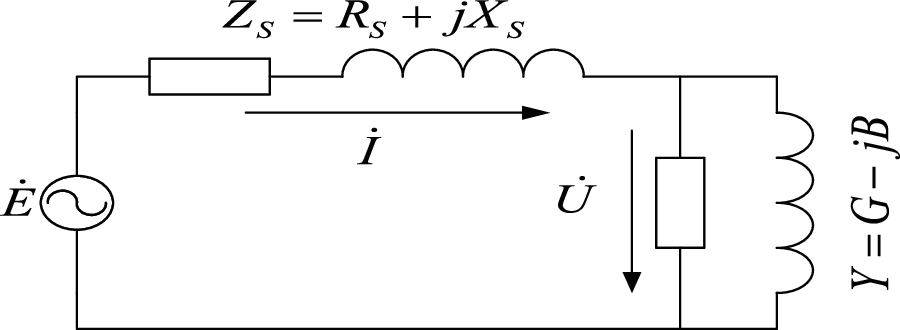
Figure 3: Fixed-frequency heat pump equivalent topology
It can be seen that the relationship between the starting current of the fixed-frequency heat pump and the active power and reactive power is:
The voltage sag caused by the starting current on ZS is shown in Eq. (2).
Eq. (2) can be simplified. See Eq. (3).
From the above analysis, it can be seen that the fixed-frequency air-source heat pump will indeed produce a voltage sag when it is started, and its size is related to the impedance of the access point, active power, reactive power, and load voltage.
2.2.2 Variable-Frequency Air-Source Heat Pump
The main working parts of the variable-frequency air-source heat pump can be equivalent to AC-DC-AC variable-frequency device and compressor, and its structure is shown in Fig. 4.
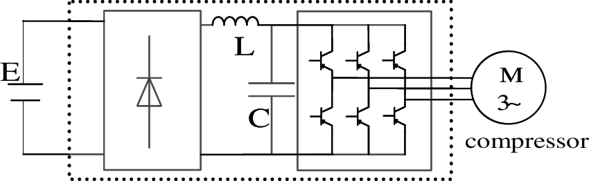
Figure 4: Variable-frequency heat pump equivalent topology
It can be seen from Fig. 4 that the frequency conversion device covers the rectification and inverter parts, and the rectification and inverter components composed of a large number of power electronic components are standard non-linear equipment so that the frequency conversion heat pump will cause harmonic pollution to the grid.
The literature in [14] carried out Fourier decomposition on the AC side current of the rectifier circuit and found that the AC side harmonics have the following law: the harmonic order is mainly odd, the higher the harmonic order, the smaller the harmonic amplitude.
3 Large-Scale Heat Pump Application Scenarios
According to the current mature technologies and application practices, the “electricity substitution” policy guides village residents to use air-source heat pumps, ground-source heat pump equipment, and high-efficiency, low-emission gas heating equipment with a higher coefficient of performance (COP). The policy also promotes fixed-frequency or variable-frequency air-source heat pumps and encourages air-source heat pumps to use environmentally friendly refrigerants. For the installation of heat pumps in the whole village for heating, the municipal finance will give high subsidies to reduce the burden on households. At the same time, in the large-scale application of heat pumps, the village government often purchases the same type of heat pumps and installs them collectively. Therefore, when we study the power quality of heat pumps in large-scale applications, at the same time, we can study the power quality problems of large-scale fixed-frequency heat pumps and variable-frequency heat pumps.
3.2 Definition of Penetration Rate
The penetration rate of large-scale electric heating applications refers to the ratio of the total power of large-scale electric heating applications to the total power of all low-voltage loads in a particular area. The specific formula is shown in Eq. (4).
where: η is the penetration rate of electric heating (%); PERH is the total power (kW) of the stable operation of electric heating; PT is the total power of the low-voltage side of the distribution transformer (kW); PLV is the total power (kW) of ordinary loads in the low-voltage distribution network.
Take the low-voltage distribution network of a particular village as an example to study the power quality of heat pumps connected to the grid under different penetration rates. The Electric Power Science Research Institute of State Grid Jiangxi Electric Power Co., Ltd. (China) provided the village network map. The topology of the distribution network is shown in Fig. 5. According to the wiring diagram of the village’s low-voltage distribution network and user load parameters, a comprehensive simulation model of large-scale heat pump access to the distribution network was built in simulink. In the simulation model, since only the power quality of the heat pump is considered, the fixed-frequency heat pump is replaced by a single-phase asynchronous motor, and the variable frequency heat pump is replaced by a frequency converter and a three-phase motor. Simulation parameters are shown in Table 1, the voltage level is 10 kV, the short-circuit capacity of the low-voltage station area is 10MVA, there are 140 residents in total, and the wire types are BLV and VLV. After launching the “Electric Energy Substitution” program, the village has all installed air-source heat pump equipment, and the average power supply capacity of electric heating households has been increased from 1 to 5 kw.
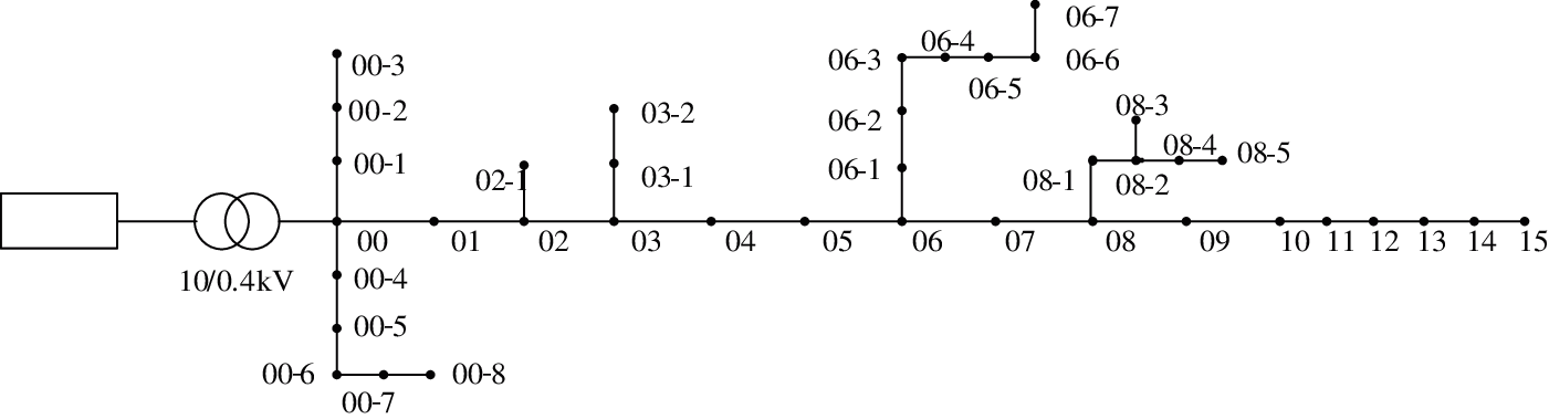
Figure 5: Topological diagram of a district distribution network
A field test was conducted on the power quality problem in the low-voltage station area. The test helped verify whether the impact of large-scale electric heating on the power quality of the power grid is the same as the simulation results. The test points are shown in Fig. 6.

Figure 6: Schematic diagram of measuring points in a village transformer room
4 Influence After the Fixed-Frequency Heat Pump is Connected
4.1 Analysis of the Simulation Results of a Single Fixed-Frequency Heat Pump
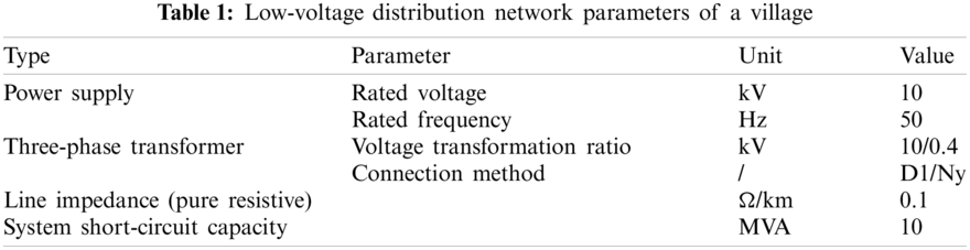
A simulation analysis of individual heat pump equipment connected to the distribution network was carried out to study the characteristics of large-scale heat pumps connected to the distribution network. According to the fixed-frequency heat pump structure, a simulation model is built in Simulink. Observe the voltage sag when a single fixed-frequency heat pump starts under different circuit resistances, as shown in Fig. 7.
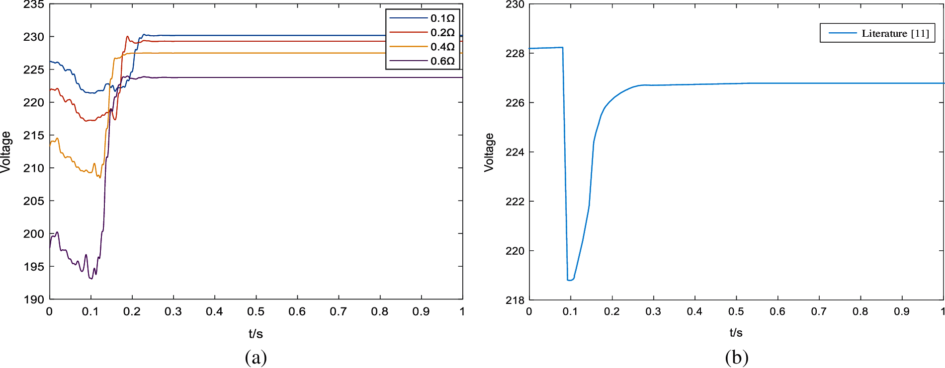
Figure 7: Voltage dip when the fixed-frequency heat pump starts (a) Starting voltage drop under different line resistance (b) Voltage drop in literature [11]
Fig. 7 shows that there will be a transient voltage drop when the fixed-frequency heat pump is started. As the line resistance increases, the voltage drop amplitude increases. At the same time, this phenomenon is also pointed out in Document 11. Although the voltage sag caused by a single heat pump will not significantly impact the power grid, when multiple heat pumps are running, the voltage sag caused to the power grid needs to be considered.
4.2 Analysis of Simulation Results of Large-Scale Application of Fixed-Frequency Heat Pump
According to the built simulation model, the average power of the air-source heat pump is set to 5.0 kW, and the average power of the ordinary electric load is 1.0 kW. There are 0, 24, 54, and 140 fixed-frequency heat pumps connected to the distribution network, respectively, and the corresponding penetration rates are 0%, 40%, 60%, and 80%. Select 0–15 nodes on the mainline, and observe the influence of the air-source heat pump starting simultaneously on the voltage sag of each node of the low-voltage distribution network under different permeability, as shown in Fig. 8.
Figure 8: Voltage dip when the fixed-frequency heat pump starts (a) Phase A simulation results (b) Phase B simulation results (c) Phase C simulation results
It can be seen from Fig. 8 that as the permeability of the fixed-frequency heat pump increases, the voltage sag caused by the start of the heat pump increases, and phase C has the largest increase. When the fixed-frequency heat pump is not connected to the station area, the voltage sag of each node of the three phases is not lower than the voltage sag threshold of 0.9 p.u. [15]. When the penetration rate of the fixed-frequency heat pump is 40%, the start of the heat pump has caused the terminal voltage of the B and C phase lines to be lower than the voltage sag threshold. When the penetration rate of the fixed-frequency heat pump reaches 60%, the start of the heat pump causes the terminal voltage of the three-phase line to be lower than the voltage sag threshold. When the penetration rate of the fixed-frequency heat pump reaches 80%, the three-phase voltage will drop drastically when the fixed-frequency heat pump starts, and the terminal voltage of the three-phase A, B, and C drops to 0.759, 0.604, 0.534 p.u., respectively. This will seriously affect the regular use of other electrical equipment in the station.
After the fixed-frequency heat pump is started, due to the unbalanced three-phase load, it may cause the three-phase unbalance problem in the station area. Calculate the magnitude of the three-phase current unbalance at the common connection point, and the results are shown in Table 2.
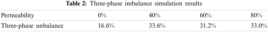
It can be seen from Table 2 that when the fixed-frequency heat pump is connected on a large scale, the three-phase imbalance in the station area has nearly doubled. However, with the increase of the fixed-frequency permeability, the three-phase unbalance degree in the station area did not show apparent regularity. China Power Grid Corporation enterprise standard Q/GDW15192014 “Distribution Network Operation and Maintenance Regulations” stipulates [16]: Dyn11 wiring transformer load imbalance is not more than 25%. The three-phase load in this station has an unbalance degree of more than 30% in the fixed-frequency heat pump penetration rate of 40%, 60%, and 80%, which has exceeded the standard of the State Grid Corporation.
Under test conditions, observe the fundamental power and power factor of the incoming line of the fixed-frequency heat pump in the village. Since it is impossible to start and stop the fixed-frequency heat pumps of multiple users at the same time in the test environment, three heat pumps of three phases are selected for 24 h test on the fundamental wave power and fundamental wave power factor of the inlet side, and the trend of change is shown in Fig. 9.

Figure 9: Three-phase fundamental power change trend graphs
It can be seen from Fig. 9 that there are many burrs in the fundamental power trend on the inlet side of the fixed-frequency heat pump. Therefore, within a short period when the equipment is started, the reactive power will have a greater impact, the active power will drop, the inrush current will be greater, and the power factor will be reduced.
Test the effective value of the fundamental wave of the bus voltage, and the test result is shown in Fig. 10.
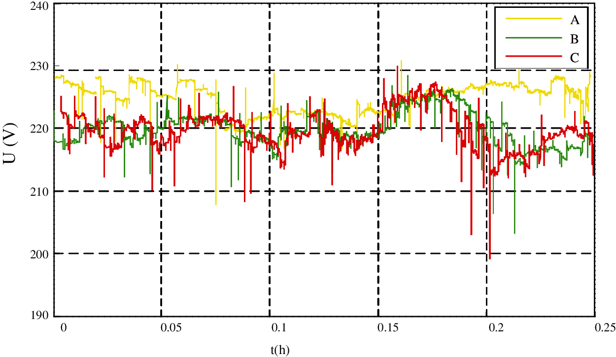
Figure 10: Three-phase bus voltage trend chart
It can be seen from Fig. 10 that the three-phase voltage has dropped repeatedly during the test period, and the C-phase has the largest drop, with a maximum drop of 0.86 p.u., which is already below the voltage sag threshold. Since multiple fixed-frequency heat pumps did not start simultaneously in the test environment, the measured voltage drop phenomenon was not as evident as the simulation result. However, it is sufficient to prove that the large-scale fixed-frequency heat pump will cause voltage sag problems in the distribution network.
5 Influence after the Variable-Frequency Heat Pump is Connected
5.1 Analysis of Simulation Results of a Single Unit of Variable-Frequency Heat Pump
Build a simulation model in Simulink according to the structure of the variable-frequency heat pump. Observe the harmonic content generated when a single variable-frequency heat pump runs, as shown in Table 3.
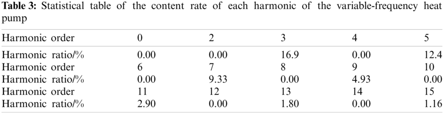
It can be seen from the simulation results that the variable-frequency heat pump will inject harmonics into the grid side. The harmonic order is mainly an odd number, and the third harmonic ratio is the highest, reaching 16.9%. The harmonic content rate decreases with the increase of the harmonic order.
5.2 Analysis of Simulation Results of Large-Scale Application of Variable-Frequency Heat Pump
According to the simulation model built, 0, 24, 54, and 140 variable-frequency air-source heat pumps are connected to the distribution network, respectively, and the corresponding penetration rates are 0%, 40%, 60%, and 80%. Observe the harmonic content under each permeability at the common connection point, as shown in Tables 4–7.
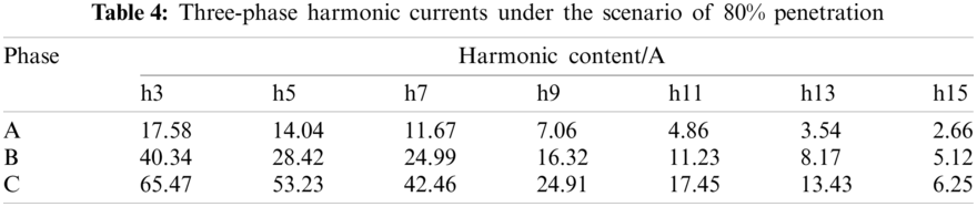
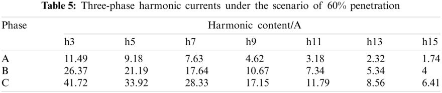
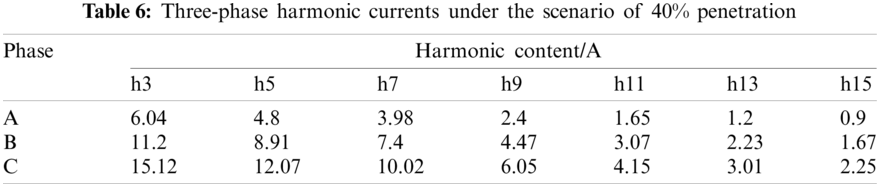
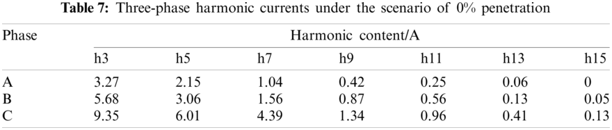
From the simulation results, it can be seen that with the increase of the permeability of the variable-frequency heat pump, the amplitude of each harmonic current increases, and the third harmonic has the largest increase. When the penetration rate reaches 80%, the amplitude of the 3rd harmonic current generated by phase C is as high as 65.47 A, and the amplitude of the 5th, 7th, and ninth harmonic currents are also maintained above 20 A. According to the short-circuit capacity of the station area, the third harmonic current of phase C under the scenario of 80% penetration rate exceeds the allowable value of 62 A for user injection into the low-voltage distribution network harmonic current specified in the standard [17]. When the penetration rate is 60% and 40%, the harmonics of the three phases do not exceed the allowable value of harmonic current injected into the low-voltage distribution network by users in the standard. Therefore, it can be inferred that different penetration rates of down-conversion heat pumps have different effects on the harmonics of the distribution network. When the penetration rates of the frequency conversion heat pumps reach 80%, a large number of frequency conversion air-source heat pumps will cause harmonic pollution to the distribution network. As the penetration rate of variable-frequency heat pumps increases, the harmonic currents in the station area will gradually exceed the standard.
Under the test conditions, the harmonic current and harmonic distortion rate were tested at the public connection point of the village, and the changing trend is shown in Fig. 11.
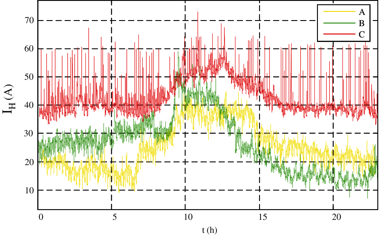
Figure 11: Harmonic current variation trend diagram at the common connection point
By observing the trend graph of harmonic content and total harmonic distortion at the common connection point, it can be found that there are different degrees of harmonic current in each phase. Phase C has the largest harmonic current, and the peak value of total harmonic current reaches 76.03 A. The simulation result comparison shows that the tested harmonic current is closer to the simulation result under the scenario of 80% permeability, which proves that the large-scale variable-frequency heat pump causes harmonic pollution to the distribution network.
By analyzing the mechanism of power quality problems generated by heat pump equipment, modeling and simulation are carried out to study the power quality impact of large-scale heat pump equipment connected to the low-voltage distribution network. It can be seen from the simulation results that as the load permeability of the fixed-frequency heat pump increases, the sag depth and duration increase. When the penetration rate of fixed-frequency heat pumps increased to 40%, the voltage sag of the distribution network exceeded the grid standard. With the increase in the permeability of variable-frequency heat pumps, harmonic voltage and current contents also increase. However, the increase in harmonic voltage is slight, and the content is low. The noticeable increase is in the 3rd harmonic current. When the frequency conversion heat pump penetration rate reaches 80%, the third harmonic current at the public connection point of the power grid has reached 65 A.
It can be seen from the test results that the fundamental reactive power of the fixed-frequency heat pump has an upward impact burr when the fixed-frequency heat pump is started, and the voltage drops to 0.9 p.u. several times during the test. When a large-scale variable-frequency heat pump runs, each phase has a sizeable harmonic current. The harmonic current is mainly the 3rd harmonic, and the total harmonic current of phase C is as high as 76 A.
Regarding the voltage sag caused by the start-up of the fixed-frequency heat pump, measures such as the optimization of the access position and the start-up sequence control should be taken to control it. The variable-frequency heat pump has scattered running time and large rated power, and the harmonics generated by it are mainly affected by the peak load. For the problem of harmonic pollution caused by variable-frequency heat pumps, measures to suppress harmonics should be taken in the area with a higher proportion of variable-frequency heat pumps.
Funding Statement: Science and Technology Project of State Grid Corporation of China, Scale application and benefit evaluation of typical power substitution technology considering the influence of power quality (52182018000H).
Conflicts of Interest: The authors declare that they have no conflicts of interest to report regarding the present study.
1. State Grid Corporation of China (2013). The state grid corporation of China fully started the replacement of electric energy. Cambridge: Cambridge University Press. http://www.sasac.gov.cn/n2588025/n2588124/c4148394/content.html. [Google Scholar]
2. The people’s Government of Beijing Municipality (2013). Notice of the Beijing municipal people’s government on printing and distributing the beijing clean air action plan for 2013–2017. http://www.zhb.gov.cn/gzfw_13107/zcfg/hjjzc/dfhjjjzc/201605/t20160520_346665.shtml. [Google Scholar]
3. Maddah, S., Goodarzi, M., Safaei, M. R. (2020). Comparative study of the performance of air and geothermal sources of heat pumps cycle operating with various refrigerants and vapor injection. Alexandria Engineering Journal, 59(6), 4037–4047. DOI 10.1016/j.aej.2020.07.009. [Google Scholar] [CrossRef]
4. Deymi-Dashtebayaz, M., Maddah, S., Goodarzi, M., Maddah, O. (2020). Investigation of the effect of using various HFC refrigerants in geothermal heat pump with residential heating applications. Journal of Thermal Analysis and Calorimetry, 141(1), 361–372. DOI 10.1007/s10973-020-09539-5. [Google Scholar] [CrossRef]
5. Keepaiboon, C., Dalkilic, A. S., Mahian, O., Ahn, H. S., Wongwises, S. et al. (2020). Two-phase flow boiling in a microfluidic channel at high mass flux. Physics of Fluids, 32(9093309. DOI 10.1063/5.0023758. [Google Scholar] [CrossRef]
6. Mehrdad, S., Dadsetani, R., Amiriyoon, A., Leon, A. S., Safaei, M. R. et al. (2020). Exergo-economic optimization of organic rankine cycle for saving of thermal energy in a sample power plant by using of strength pareto evolutionary algorithm II. Processes, 8(3), 264. DOI 10.3390/pr8030264. [Google Scholar] [CrossRef]
7. Dadsetani, R., Sheikhzadeh, G. H. A., Safaei, M. R., Alnaqi, A. A., Amiriyoon, A. (2019). Exergoeconomic optimization of liquefying cycle for noble gas argon. Heat and Mass Transfer, 55(7), 1995–2007. DOI 10.1007/s00231-018-2501-5. [Google Scholar] [CrossRef]
8. Shadloo, M. S., Rahmat, A., Karimipour, A., Wongwises, S. (2020). Estimation of pressure drop of two-phase flow in horizontal long pipes using artificial neural networks. Journal of Energy Resources Technology–Transactions of the ASME, 142(11), 106634. DOI 10.1115/1.4047593. [Google Scholar] [CrossRef]
9. Li, W., Zhang, F., Zhang, L., Yan, Z., Zhou, C. et al. (2016). Analysis and evaluation of harmonic in the coal-to-electricity project considering differences of electric heating radiators. Power system and clean energy, 32(10), 34–41. DOI 10.3969/j.issn. [Google Scholar] [CrossRef]
10. Yuan, Z., Bao, H., Zhou, L. M., Zhang, H. Y., Yang, J. H. et al. (2019). Analysis on the impacts of large-scale electric heating radiators to power quality of distribution networks. Electrical Measurement & Instrumentation, 56(1), 60–68+101. DOI 10.19753/j.issn1001-1390. [Google Scholar] [CrossRef]
11. Zhou, L. M., Zhang, H. Y., Bao, H., Jin, K. Y., Yang, J. H. et al. (2018). The impact analysis of large scale air-source heat pumps on operation characteristics and power quality of distribution networks. Power System and Clean Energy, 34(5), 74–82. DOI 10.3969/j.issn.1674-3814. [Google Scholar] [CrossRef]
12. Luo, Z. L. (2015). Improvement analysis on motor of air-source heat pump’s compressor. Refrigeration and Air-Conditioning, 15(5), 26–28. [Google Scholar]
13. Zhang, M., Niu, T., Guo, X. Y. (2016). Comparison on formula and simulation calculation of grid voltage drop at time of motor starting. Electrotechnics Electric, 1(8), 15–18+46. [Google Scholar]
14. Liu, J. J., Wang, Z. A. (1996). Harmonic analysis of LC-filtered single phase bridge rectifiers. Power Electronics, 1(2), 5–9. [Google Scholar]
15. Zhou, S. J., Yu, K. S., Tan, Z. Q., Liu, X., Lin, H. X. et al. (2008). National standards of the people’s republic of China-power quality power supply voltage deviation: GB/T 12325–2008. China: China Electric Power Press. [Google Scholar]
16. Dan, L. S., Shen, H. J., Zhu, S. P., Ning, X., Zhu, M. et al. (2014). Regulations of operating and maintenance for distribution network. China: China State Grid Corporation. [Google Scholar]
17. Liu, J. C., Lin, H. X., Zhang, P., Jiao, L., Ceng, Y. Y. (1993). Power quality—Interharmonics in public supply network. China: China Standard Press. [Google Scholar]
 | This work is licensed under a Creative Commons Attribution 4.0 International License, which permits unrestricted use, distribution, and reproduction in any medium, provided the original work is properly cited. |