| Energy Engineering |
DOI: 10.32604/ee.2022.016769
ARTICLE
A Fault Current Limiting Hybrid DC Circuit Breaker
Mechanical and Control Engineering College, Shengli College China University of Petroleum, Dongying, 257061, China
*Corresponding Author: Lei Huang. Email: 2015016@slcupc.edu.cn
Received: 25 March 2021; Accepted: 01 July 2021
Abstract: Due to the low impedance characteristic of the high voltage direct current (HVDC) grid, the fault current rises extremely fast after a DC-side fault occurs, and this phenomenon seriously endangers the safety of the HVDC grid. In order to suppress the rising speed of the fault current and reduce the current interruption requirements of the main breaker (MB), a fault current limiting hybrid DC circuit breaker (FCL-HCB) has been proposed in this paper, and it has the capability of bidirectional fault current limiting and fault current interruption. After the occurrence of the overcurrent in the HVDC grid, the current limiting circuit (CLC) of FCL-HCB is put into operation immediately, and whether the protected line is cut off or resumed to normal operation is decided according to the fault detection result. Compared with the traditional hybrid DC circuit breaker (HCB), the required number of semiconductor switches and the peak value of fault current after fault occurs are greatly reduced by adopting the proposed device. Extensive simulations also verify the effectiveness of the proposed FCL-HCB.
Keywords: Fault current limiting hybrid DC circuit breaker (FCL-HCB); high voltage direct current (HVDC) grid; fault current limiting; fault current interruption; DC circuit breaker
Compared with the traditional line commutated converter (LCC)-based high-voltage DC (HVDC) transmission systems, HVDC grids based on modular multilevel converter (MMC) have more advantages, such as independent control of active and reactive power, easiness to form a multi-terminal network, power supply for passive networks, etc. [1]. These characteristics of the MMC-HVDC grid have solved the problem of large-scale renewable energy integration [2], therefore it has become a research hotspot in recent years.
One of the important factors restricting the development of the HVDC grid is the fault isolation technology [3]. At present, there are two main fault isolation schemes for HVDC grids [4,5]: one is a combination scheme based on converters with fault-blocking capability, such as full-bridge (FB)-MMC, and disconnectors; the other is based on converters without fault-blocking capability, such as half-bridge (HB)-MMC, and DC circuit breakers (DCCBs). The former scheme relies on the FB-submodule (SMs) in the converter to generate a reverse voltage to clear the fault current after the occurrence of the fault, and then uses disconnectors to isolate the fault line. Because this scheme requires that the number of FB-SMs in the converter accounts for more than 50% of the total number of SMs, it will cause additional investment costs and operation power losses [1]. In addition, the scheme will cause short-term outage of the HVDC grid, which is not conducive to the safe and stable operation of the HVDC grid [2]. Like the alternative current (AC) grid, the latter scheme adopts DCCBs to isolate the fault line directly without causing additional problems. Therefore, this scheme is an ideal solution for HVDC grid fault isolation.
Currently, the proposed DCCBs can be divided into three main types, namely mechanical DC circuit breakers (MCBs), solid-state DC circuit breakers (SSCBs) and hybrid DC circuit breakers (HCBs) [6–9]. MCBs use fast mechanical switches to interrupt the fault current, and its action speed is relatively slow. Besides, because there is no zero-crossing point in the fault current of the HVDC grid, the MCB requires auxiliary circuit to manually create it [6]. The SSCB use the current-block capability of power electronic devices to interrupt fault current and it can operate extremely fast (within 1 ms). However, it requires high investment cost and may cause large power losses [7]. SSCBs are usually used in the power systems of ships, submarines, etc. [8]. The HCB combines the advantages of the MCB and the SSCB, which has the characteristics of low conduction loss and fast action speed [9]. However, it requires many semiconductor switches in series to withstand the transient interruption voltage (TIV), so the investment cost is relatively high. At present, Nanrui Electric Co., Ltd., China and China Xidian Electric Co. Ltd., China have both successfully developed the 500 kV HCBs.
Due to the low-impedance characteristic of the HVDC grid, the fault current develops extremely fast, and within a few milliseconds it can reach several times or even tens of times the rated current. To suppress the rising speed of the fault current, many fault current limiters have been proposed [10–14]. A fault current limiter based on thyristors has been proposed [10]. The device can put a current limiting reactor into operation to limit the fault current during the fault. However, in order to achieve the bidirectional current limiting effect, it is necessary to pre-charge the two capacitors, and the structure is more complicated. To limit the rise speed of the fault current, a method by connecting thyristors and energy dissipation resistors in parallel of the current limiting reactor has been proposed [11]. In addition to the current limiting capability, this method can also shorten the energy dissipation time of the current limiting reactor after the DCCB operates. A high inductance solid-state fault current limiter based on DC reactor has been proposed, which can decrease the fault current with small time delay [12]. A liquid metal current limiter is proposed for medium voltage DC (MVDC) networks [13]. After 1.53 ms of the current limiting reaction time, the current limiter can limit the fault current to half of that without the current limiter. A current-commutation-based fault current limiter has been proposed [14]. By combining the half-control unit and the full-control unit, the fault current can be greatly limited without much negative influence on the DC system.
Most of the fault current limiters proposed at present are independent devices, so installing the fault current limiter requires additional investment costs. Fault current limiting devices have fault current limiting function, HCB on the cut off the fault current has a superior performance. HCB which has the capability of fault current limiting can be implemented in fault current limiting. FCL-HCB can further inhibit the rise of the fault current, and reduce the pressure of the HCB to cut off the fault current, Therefore, a current limiting hybrid DC circuit breaker topology is proposed [15], but it still relies on the DC reactor in the line for fault current limiting. Li et al. proposed a fault current limiting method [16,17]. When a fault occurs, the shunt reactor will be in series state, thus inhibiting the fault current. However, the fault breaking speed of the shunt reactor is not significantly improved compared with the traditional ABB HCB. To solve this problem, this paper proposes a fault current limiting hybrid DC circuit breaker (FCL-HCB). By integrating the current limiting circuit (CLC) into the HCB, additional equipment investment is avoided. Compared the proposed FCL-HCB with the traditional HCB, the peak value of the fault current is reduced by 35.63%, the energy consumption of the main breaker (MB) is reduced by 47.13%, and the energy dissipation time is shortened by 18.28%.
The rest of the paper is organized as follows. The traditional HCB and the proposed FCL-HCB are introduced in Section 2. In Section 3, the operation principle of FCL-HCB is elaborated. The effectiveness of the proposed FCL-HCB is verified in Section 4. The comparison of the traditional HCB and the proposed FCL-HCB is developed in Section 5. In Section 6, some discussions are given.
The HCB has been first proposed by ABB [7], and its topology is shown in Fig. 1.
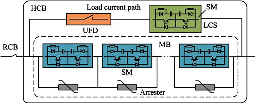
Figure 1: The topology of the traditional HCB
The traditional HCB consists of a residual current breaker (RCB), a load current branch and an MB (Fig. 1). The load current branch is a series branch of the load commutation switch (LCS) and the ultra-fast disconnector (UFD). The MB is composed of many IGBT-based SMs connected in series and arresters. The number of SMs connected in series in the MB may reach hundreds for the high-voltage application, and this will result in high manufacturing cost. The RCB is used to isolate the faulty line physically after the completion of the current interruption process.
When the HCB receives the trip command from the protection, the MB is turned on and the LCS is turned off. At this time, the fault current starts to be transferred to the MB. When the fault current of the load current branch drops to zero, the UFD starts the opening action. The opening time of UFD in zero current state is about 2 ms [18]. After the UFD completes the opening action, the MB is turned off, and the fault current is transferred to the arresters to be dissipated.
The topology of the FCL-HCB proposed in this paper is shown in Fig. 2. It contains an RCB, a load current path, a CLC, an MB and four diode branches D1–D4. The RCB and the load current path are the same as those of the traditional HCB. The MB in the FCL-HCB contains many SMs and arresters. However, the SMs in the MB of the FCL-HCB are different from those of the traditional HCB. The comparison of those two kinds of SMs is illustrated in Fig. 3. Because the direction of the current flowing through the MB of FCL-HCB has been fixed, the SM in the FCL-HCB requires only one IGBT, while the SM in the traditional HCB requires two IGBTs to achieve the bidirectional current interruption. The CLC is composed of two thyristor branches T1, T2, a capacitor C, a current limiting inductor L, an energy absorption resistor Re and a diode branch De. The capacitor C is pre-charged, and the polarity of the pre-charged voltage is negative. Several pre-charging methods for capacitors have been proposed [19–21]. Reference [19] proposes to use an isolated auxiliary power supply to charge the capacitor. A laser energy charging scheme for high-voltage capacitors is proposed in [20]. In [21], the authors realize high-voltage capacitor charging by the DC system. The pre-charging methods of the capacitor can be selected according to the actual situation. The operation principles of the proposed FCL-HCB are elaborated in the next section.
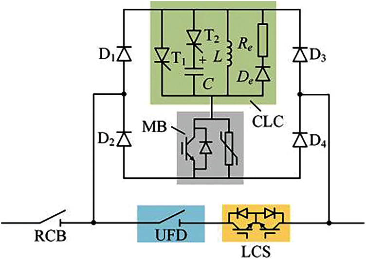
Figure 2: The topology of the FCL-HCB
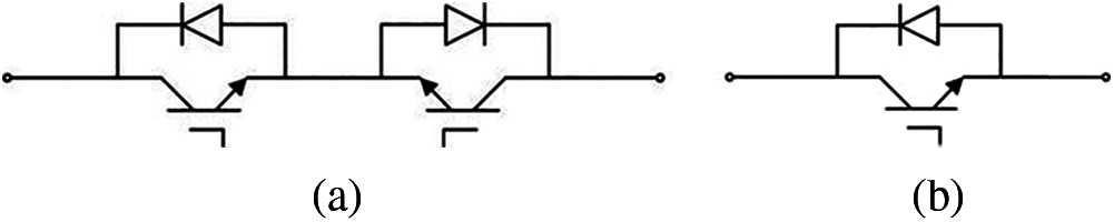
Figure 3: The comparison of SMs in the MB of the traditional HCB and the proposed FCL-HCB. (a) The traditional HCB; (b) The proposed FCL-HCB
3 Operation Principle of FCL-HCB
For the safety of the electronic devices, the HVDC grid usually has very high requirements for fault isolation speed. Taking the Zhangbei four-terminal HVDC grid in China as an example, the protection is required to send trip signal within 3 ms, and the HCB is required to interrupt fault current within 3 ms [22]. For the traditional HCBs, the time from the occurrence of the fault to the fault current being interrupted is 6 ms, so the rise time of the fault current is 6 ms. At this time, the fault current has reached an extremely high value which causes great pressure to the MB. In addition, because the fault identification time left for the protection system is only 3 ms, the reliability of the protection system is greatly challenged.
In order to solve the above problems, the FCL-HCB proposed in this paper puts the CLC into operation immediately when the overcurrent of the protected line is detected, instead of waiting for the trip command of the protection system. Because the detection time of the overcurrent can be extremely short (less than 0.5 ms), the CLC in the FCL-HCB can greatly reduce the rising speed of the fault current. If the cause of the overcurrent is a fault in the protected line, the FCL-HCB can continue to operate to interrupt the fault current. Otherwise, if the cause of the overcurrent is a non-fault factor or the fault is an external fault, the CLC can exit and the normal operation can be resumed. It is worth noting that during the process of fault current interruption of the FCL-HCB, because the current limiting inductor in the CLC is bypassed by the energy dissipation resistor Re, the energy consumed by the arresters in the MB and the total energy consumption time are both greatly reduced. Thereby, the pressure of devices in the HVDC grid to withstand large currents is greatly reduced.
3.1 Operation Principle After Occurrence of Internal Fault
The detailed operation principle of the proposed FCL-HCB is as follows:
1. Stage I:
The two-terminal test system is utilized to analyze the operation principle of the FCL-HCB (Fig. 4). The converters S1 and S2 are MMCs, and their output voltages are assumed to be constant during the fault current limiting and the fault current interruption, and their values are considered as Udc. Therefore, during the analysis process, the converters S1 and S2 can be assumed as an ideal voltage source Udc in series with an equivalent arm inductance Leq. The pre-charged voltage of the capacitor C is -Ucp. The length of the DC line is l km. The L-model of the DC line has been adopted to simplify the analysis, and the inductance of the DC line is Lline. The load current is Iload. In addition, the DC inductor Ldc is configured. The occurring time of a short-circuit fault F is assumed as t0 at αl km from the converter S1. After the occurrence of the fault, both converters S1 and S2 feed fault current into the fault point. The FCL-HCB1 in Fig. 4 is selected as the research objective. The overcurrent is detected at time t1. The fault current in the FCL-HCB has been illustrated in red (Fig. 5).
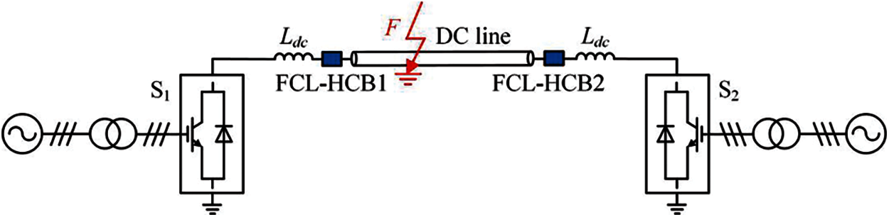
Figure 4: The test system
2. Stage II:
When the overcurrent is detected at time t1, the FCL-HCB starts to operate. At the same time, the thyristor branch T1 is triggered and the LCS and the MB are both turned on. The fault current starts to be transferred from the load current path to the thyristor branch T1 and the MB via the diode branches D1 and D4. At time t2, the current flows through the load current path decays to zero, and the UFD starts to open. The UFD completes the open process at time t3. The time interval between t2 and t3 can be considered as 2 ms. During this stage, the equivalent diagram of the FCL-HCB is shown in Fig. 6. The dotted red line in Fig. 6 indicates that the fault current has been decreased. The total fault current is(t) during the period from time t0 to time t3 can be adopted as follows:
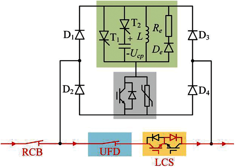
Figure 5: The current in the FCL-HCB in Stage I
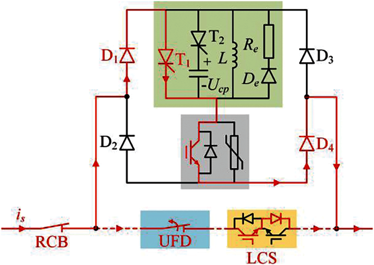
Figure 6: The current in the FCL-HCB in Stage II
3. Stage III:
At the end of the opening action of the UFD at time t3, the thyristor branch T2 is triggered. Because of the reverse voltage applied on the thyristor branch T1 by the pre-charged voltage of the capacitor C, the current flowing through the thyristor branch T1 has been decreased. After the thyristor branch T1 withstands the reverse voltage for a period, its forward blocking ability can be restored at time t4. The block time of the existing fast thyristor requires about tens to hundreds of microseconds [10]. Stage 3 starts at the trigger time of thyristor T2 and ends at the time when the thyristor T1 is blocked completely. During this stage, since the thyristor T1 is in the process of blocking and has not been completely blocked, no current will flow in the current limiting inductor and De-Re. During this stage, the current paths in the FCL-HCB are illustrated in Fig. 7.
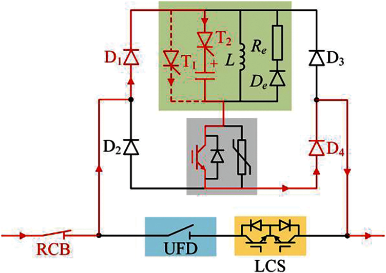
Figure 7: The current in the FCL-HCB in Stage III
4. Stage IV:
After the block of the thyristor T1, the capacitor C and the current limiting inductor L are connected in parallel. The current continues to charge the capacitor C, and the voltage of the capacitor changes from negative value to positive value. After the positive voltage of the capacitor rises to its peak value, the current of the capacitor decays to zero at time t5. At this time, the thyristor branch T2 is blocked due to its reverse voltage and zero current condition. Then, the current limiting inductor L is connected in series to the current path, and the operation of the current limiting is completed. The current paths in the FCL_HCB are shown in Fig. 8. The equivalent circuit in this stage is shown in Fig. 9.
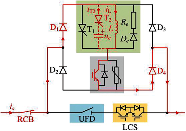
Figure 8: The current in the FCL-HCB in Stage IV
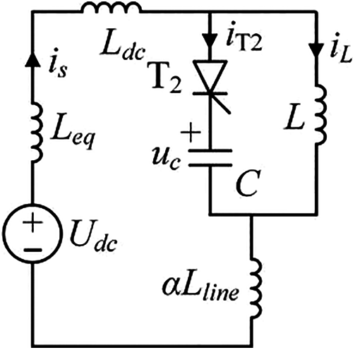
Figure 9: The equivalent circuit in Stage IV
According to Fig. 9, the following differential equations can be obtained.
The initial value conditions of the above differential equations can be described by the following equations:
The expressions of the current iL(t) and the voltage uc(t) can be obtained by (2) and (3).
where
5. Stage V:
After time delay, the trip signal is received by the FCL-HCB from the protection system at time t6. The MB is commanded to turn off immediately. Then, the fault current is commutated from the SMs to the arresters to be dissipated. Besides, due to the large TIV generated by the arresters, the fault current in the current limiting inductor L is forced into the Re-De branch. Therefore, the energy dissipation time of the arresters can be greatly reduced. At time t7, the current through the MB and the RCB decreases to zero. However, the energy dissipation of the L-Re-De loop may have not completed due to a larger time constant. The current paths in the FCL-HCB are shown in Fig. 10.
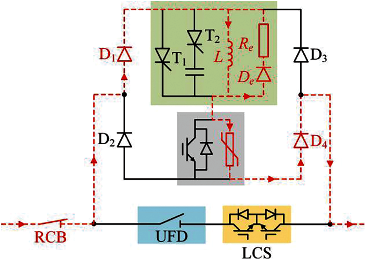
Figure 10: The current in the FCL-HCB in Stage V
6. Stage VI:
After the fault current interruption at time t7, the RCB is forced to open to isolate the fault line physically. The current in the current limiting inductor will be dissipated by the resistor Re and it decreased to zero finally. The current paths during this stage are shown in Fig. 11.
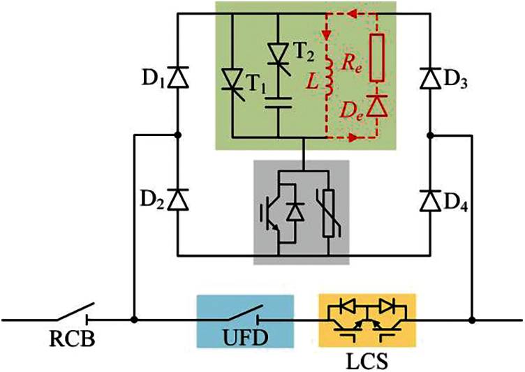
Figure 11: The current in the FCL-HCB in Stage VI
3.2 Operation Principle after Overcurrent Interference
If the fault detection result obtained at time t6 shows that there is no fault in the DC line, and the FCL-HCB needs to be restored from the current limiting state to the normal state. The operation process is listed as follows:
Firstly, the UFD is commanded to close. After a small period, the close action of the UFD is completed. Then, the LCS is turned on. After that, because the equivalent resistance of the load current path is much smaller than the total equivalent resistance of the current path D1-L-MB-D4, the current is gradually transferred into the load current path. After the completion of the current transfer, the MB is turned off, and the FCL-HCB enters the normal operation state.
According to the above analysis, the parameters of the main components in the proposed FCL-HCB are designed, including the selection of inductive components and capacitance components. At present, current limiting reactants are widely used in fault current limiting of MMC-HVDC transmission lines. Considering thet current limiting reactants used in current projects are generally 150 mH, and combined with the current limiting demand of 500 kV MMC-HVDC, the inductance value of current limiting reactance is selected as 200 mH in this paper. Considering the maximum forward voltage the capacitor must withstand is:
The capacitance value is selected according to the maximum forward voltage to be sustained by the capacitor voltage. In this paper, the capacitance of 10 uF is selected.
According to formula (4), we can get the time when the capacitor provides reverse voltage to thyristor T1 is:
Based on the formula (7), shut off time of thyristor T1 and the selection of capacitance and the capacitance selection on charging voltage, in order to ensure the thyristor reliably shut off, and we keep reverse voltage is greater than the thyristor turn-off time, therefore, on the basis of considering capacitance value selection, combined with reverse voltage thyristor of capacitance time request, to the selection of charging voltage of capacitor. Since the turn-off time of the thyristor is within tens to hundreds of milliseconds, the time for selecting the capacitor to provide the reverse voltage to the thyristor is no less than 300 ms. Combined with the selected capacitance value, the appropriate pre-charging voltage of the capacitor can be selected.
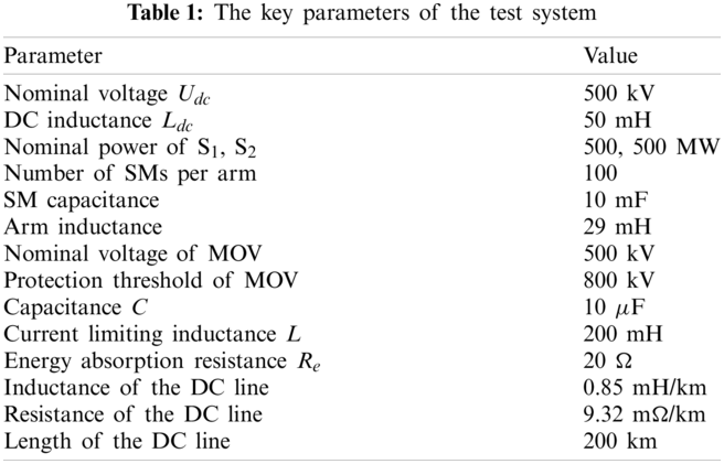
To prove the effectiveness of the proposed FCL-HCB, a unipolar test system us built with the PSCAD/EMTDC software (Fig. 4). The R-L model of the DC line is adopted. The detailed model of the MMC is utilized [23]. The pre-charge voltage of the capacitor C is −150 kV. The short-circuit fault F is detected at the midpoint of the DC line. The key parameters of the test system are shown in Table 1.
4.2 Simulation Results after Occurrence of Short-Circuit Fault F
The short-circuit fault F is detected at 4.0 s and the overcurrent is detected at 4.0005 s (Fig. 12). At the same time, the FCL-HCB starts to operation. At 4.006 s, the fault current interruption process is performed by the FCL-HCB. The operation principles are shown in Section 3.1.
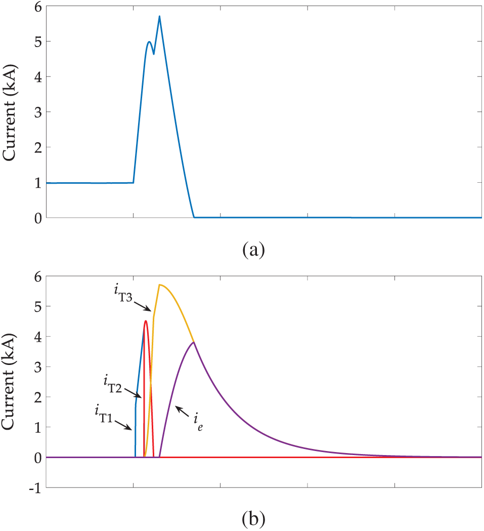
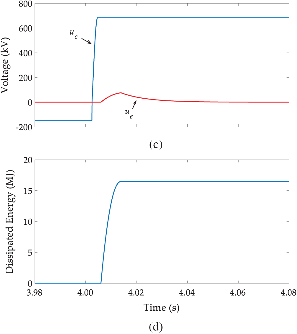
Figure 12: Simulation results after occurrence of the internal short-circuit fault F. (a) The line current; (b) The currents in the CLC (iT1 represents the current in the thyristor branch, iT2 represents the current in the capacitor branch, iT3 represents the current in the limiting inductor branch, i.e., represents the current in the resistance branch); (c) The voltages of the capacitor C and the resistor Re; (d) The dissipated energy of the arresters in the MB
During the current limiting process of the FCL-HCB, the current has transferred from the thyristor branch T1 to the thyristor branch T2, and then it transfers from the thyristor branch T2 to the current limiting inductor L. The capacitor C in the CLC reaches the peak value of nearly 700 kV. When the MB is turned off in 4.006 s, the fault current flowing through the current limiting inductor L starts to be transferred to the energy absorption resistor Re. This can speed up the energy absorption of fault current in the DC line. The fault current in the DC line decays to zero at 4.0136 s, and the current in the current limiting inductor L decays to zero at 4.061 s due to the much larger time constant. During the fault current limiting and fault current interruption process of the FCL-HCB, the peak value of the fault current flowing through the DC line is about 5.6 kA, the fault current absorption time is about 7.6 ms, and the energy consumption of the arrester in the MB is about 16.6 MJ.
4.3 Simulation Results after Overcurrent Interference
It is assumed that an overcurrent interference occurs at 4.0 s, and the overcurrent is detected after 0.5 ms. Then, the FCL-HCB changes from the normal operation state to the fault current limiting state. At 4.006 s, the FCL-HCB starts to exit the fault current limiting state, and the operation process is shown in Section 3.2. The simulation waveforms show that the current flowing through the CLC is nearly all transferred to the load current path at about 4.5 s (Fig. 13). The results indicate that the proposed FCL-HCB can exit the fault current limiting mode to the normal operation.
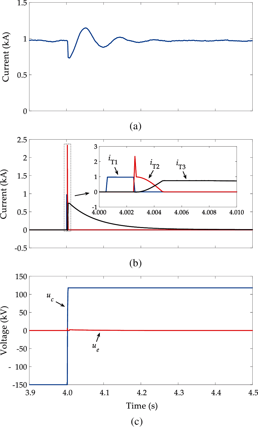
Figure 13: Simulation results after the overcurrent interference. (a) The line current; (b) The currents in the CLC (iT1 represents the current in the thyristor branch, iT2 represents the current in the capacitor branch, iT3 represents the current in the limiting inductor branch); (c) The voltages of the capacitor C and the resistor Re
5.1 Performance of Fault Current Interruption
Compared the FCL-HCB proposed in this paper with the traditional HCB, and the traditional HCB is used to interrupt the fault current. The fault condition is the same as that in Section 4.2.
The simulation results show that the peak value of the fault current flowing through the DC line is about 8.7 kA, the fault current absorption time is about 9.3 ms, and the energy consumption of the arrester in the MB is about 31.4 MJ (Fig. 14). Compared the proposed FCL-HCB with the traditional HCB, the peak value of the fault current is reduced by 35.63%, the energy consumption of the arresters in the MB is reduced by 47.13%, and the energy dissipation time is shortened by 18.28%.
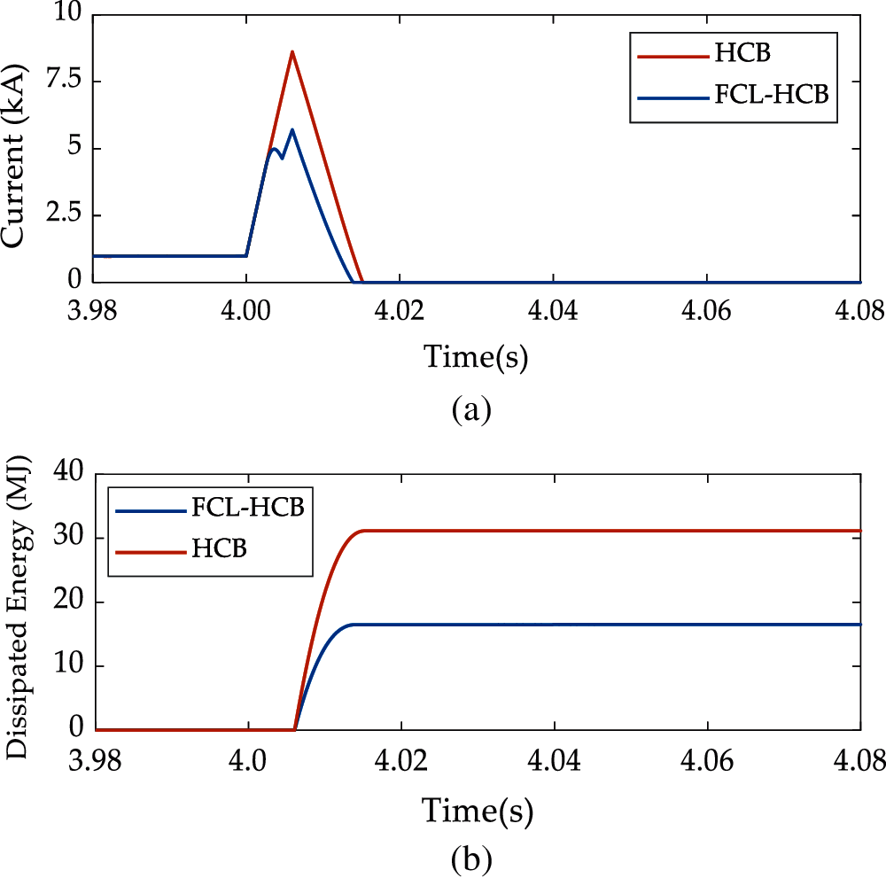
Figure 14: Simulation results (a) The line current; (b) The dissipated energy of the arresters in the MB
Because the traditional HCB and the FCL-HCB both have the RCB and the load current, their costs will no longer be considered in the economic comparison. It is assumed that the IGBT FZ3600R17HE4PHPSA1 (1.7 kV, $1524.85), the diode VS-SD1100C20C (2 kV, $80.18) and the thyristor VS-ST1230C16K1 (1.6 kV, $416.33) are used [24]. The rated voltages of the two DCCBs are all 500 kV. The protection threshold of the arresters is considered as 800 kV, and it is 1.6 times of the rated voltage. The peak value of the capacitor C in the CLC is 700 kV.
For the traditional HCB and the FCL-HCB, their MB both needs to withstand the protection voltage of the arresters which is 800 kV. In addition, for the diode branches D1–D4 of FCL-HCB, they also need to withstand the protection voltage of the arresters. For the thyristor branches T1, T2 and the diode branch De of the FCL-HCB, they need to withstand the voltage peak value of the capacitor C which is 700 kV. Therefore, the cost of the semiconductor switches of the traditional HCB and the FCL-HCB are shown in Table 2 when the voltage margin is 50%.
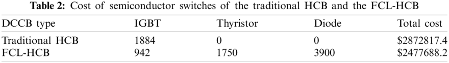
The cost of semiconductor switches of the FCL-HCB is less than that of the traditional HCB (Table 2). The energy consumption of the arresters in the FCL-HCB is about half of that of the traditional HCB. Therefore, the cost of arresters of FCL-HCB is lower. Compared with the traditional HCB, the FCL-HCB has the additional cost of the capacitor and the energy absorption resistor, but their cost is much lower than the cost of semiconductor switches and surge arresters. Therefore, the proposed FCL-HCB is more economical than the traditional HCB.
This paper proposes an FCL-HCB which has the ability of bidirectional current limiting and fault current interruption. Once an overcurrent current is detected, the CLC of FCL-HCB can be quickly put into operation, thereby the rising speed of the current is suppressed. Then, once the internal fault is identified, the FCL-HCB can quickly interrupt the fault current. Extensive simulations have proved the effectiveness of the FCL-HCB.
Compared with the traditional HCB, the FCL-HCB reduces the peak value of the fault current by 35.63%, the energy consumption of the arresters in the MB is reduced by 47.13%, and the energy dissipation time is shortened by 18.28%. In addition, the economic analysis results show FCL-HCB is more economical.
Funding Statement: This project is funded by the Dongying Science Development Fund Project (DJ2021013).
Conflicts of Interest: The authors declare that they have no conflicts of interest to report regarding the present study.
1. Balasubramaniam, S., Ugalde-Loo, C. E., Liang, J., Joseph, T., Adamczyk, A. (2020). Pole balancing and thermal management in multiterminal HVDC grids using single H-bridge-based current flow controllers. IEEE Transactions on Industrial Electronics, 67(6), 4623–4634. DOI 10.1109/TIE.2019.2926059. [Google Scholar] [CrossRef]
2. Huang, Q., Zou, G., Zhang, S., Gao, H. (2019). A pilot protection scheme of DC lines for multi-terminal HVDC grid. IEEE Transactions on Power Delivery, 34(5), 1957–1966. DOI 10.1109/TPWRD.2019.2932188. [Google Scholar] [CrossRef]
3. Bertho, R., Lacerda, V. A., Monaro, R. M., Vieira, J. C. M., Coury, D. V. (2018). Selective nonunit protection technique for multiterminal VSC-HVDC grids. IEEE Transactions on Power Delivery, 33(5), 2106–2114. DOI 10.1109/TPWRD.2017.2756831. [Google Scholar] [CrossRef]
4. Li, R., Xu, L., Yao, L. (2017). DC fault detection and location in meshed multiterminal HVDC systems based on DC reactor voltage change rate. IEEE Transactions on Power Delivery, 32(3), 1516–1526. DOI 10.1109/TPWRD.2016.2590501. [Google Scholar] [CrossRef]
5. Li, B., He, J., Li, Y., Hong, C., Zhang, Y. (2018). A novel restart control strategy for the MMC-based HVDC transmission system. International Journal of Electrical Power & Energy Systems, 99(4), 465–473. DOI 10.1016/j.ijepes.2018.01.050. [Google Scholar] [CrossRef]
6. Liu, S., Liu, Z., Jesus Chavez, J., Popov, M. (2019). Mechanical DC circuit breaker model for real time simulations. International Journal of Electrical Power & Energy Systems, 107(99), 110–119. DOI 10.1016/j.ijepes.2018.11.014. [Google Scholar] [CrossRef]
7. Zhang, S., Zou, G. B., Wei, X. Y., Sun, C. J. (2020). Diode-bridge multi-port hybrid DC circuit breaker for multi-terminal DC grids. IEEE Transactions on Industrial Electronics (in Press). [Google Scholar]
8. Liu, W., Liu, F., Zha, X., Huang, M., Chen, C. et al. (2019). An improved SSCB combining fault interruption and fault location functions for DC line short-circuit fault protection. IEEE Transactions on Power Delivery, 34(3), 858–868. DOI 10.1109/TPWRD.2018.2882497. [Google Scholar] [CrossRef]
9. Bröker, M., Hinrichsen, V. (2019). Testing metal-oxide varistors for HVDC breaker application. IEEE Transactions on Power Delivery, 34(1), 346–352. DOI 10.1109/TPWRD.2018.2877464. [Google Scholar] [CrossRef]
10. Xu, J., Zhao, X., Han, N., Liang, J., Zhao, C. (2019). A thyristor-based DC fault current limiter with inductor inserting-bypassing capability. IEEE Journal of Emerging and Selected Topics in Power Electronics, 7(3), 1748–1757. DOI 10.1109/JESTPE.2019.2914404. [Google Scholar] [CrossRef]
11. Liu, J., Tai, N., Fan, C., Chen, S. (2017). A hybrid current-limiting circuit for DC line fault in multiterminal VSC-HVDC system. IEEE Transactions on Industrial Electronics, 64(7), 5595–5607. DOI 10.1109/TIE.2017.2677311. [Google Scholar] [CrossRef]
12. Heidary, A., Radmanesh, H., Rouzbehi, K., Pou, J. (2019). A DC-reactor-based solid-state fault current limiter for HVDC applications. IEEE Transactions on Power Delivery, 34(2), 720–728. DOI 10.1109/TPWRD.2019.2894521. [Google Scholar] [CrossRef]
13. Yang, Z., He, H., Yang, F., Wu, Y., Rong, M. et al. (2019). A novel topology of a liquid metal current limiter for MVDC network applications. IEEE Transactions on Power Delivery, 34(2), 661–670. DOI 10.1109/TPWRD.2019.2892501. [Google Scholar] [CrossRef]
14. Li, B., He, J., Li, Y., Wen, W., Li, B. (2020). A novel current-commutation-based FCL for the flexible DC grid. IEEE Transactions on Power Electronics, 35(1), 591–606. DOI 10.1109/TPEL.2019.2924024. [Google Scholar] [CrossRef]
15. Jiang, D. Z., Zhang, C., Zheng, H. (2014). A scheme for current-limiting hybrid DC circuit breaker. Automation of Electric Power Systems, 38, 65–71. [Google Scholar]
16. Li, C. Y., Li, S., Zhao, C. Y. (2017). A novel topology of current-limiting hybrid DC circuit breaker for DC grid. Proceedings of the CSEE, 37, 7154–7162. DOI 10.13334/j.0258-8013.pcsee.162642. [Google Scholar] [CrossRef]
17. Li, S., Zhao, C. Y., Xu, J. Z. (2017). A new topology for current-limiting HVDC circuit breaker. Transactions of China Electrotechnical Society, 32, 102–110. DOI 10.19595/j.cnki.1000-6753.tces.161266. [Google Scholar] [CrossRef]
18. Wen, W., Huang, Y., Sun, Y., Wu, J., Al-Dweikat, M. et al. (2016). Research on current commutation measures for hybrid DC circuit breakers. IEEE Transactions on Power Delivery, 31(4), 1456–1463. DOI 10.1109/TPWRD.2016.2535397. [Google Scholar] [CrossRef]
19. Zhou, W. D., Wei, X. G., Gao, C., Luo, X., Cao, J. Z. (2014). Thyristor based hybrid arc-less high voltage direct current circuit breaker. Proceedings of the CSEE, 34, 2990–2996. DOI 10.13334/j.0258-8013.pcsee.2014.18.016. [Google Scholar] [CrossRef]
20. Gao, Y., He, Z. Y., Wang, C. H., Wei, X. G., Yang, B. J. et al. (2016). A new hybrid circuit breaker for DC-application. IEEE Transactions on Power Systems, 40, 1320–1325. DOI 10.13335/j.1000-3673.pst.2016.05.005. [Google Scholar] [CrossRef]
21. Zhao, X. B., Xu, J. Z., Yuan, J. S., Zhao, C. Y. (2018). A novel capacitor commutated hybrid DC fault current limiter. Proceedings of the CSEE, 38, 6915–6923. DOI 10.13334/j.0258-0813.pcsee.180358. [Google Scholar] [CrossRef]
22. Han, X., Sima, W., Yang, M., Li, L., Yuan, T. et al. (2018). Transient characteristics under-ground and short-circuit faults in 500 kV MMC-based HVDC system with hybrid DC circuit breakers. IEEE Transactions on Power Delivery, 33(3), 1378–1387. DOI 10.1109/TPWRD.2018.2795800. [Google Scholar] [CrossRef]
23. Wang, M., Beerten, J., van Hertem, D. (2017). Frequency domain based DC fault analysis for bipolar HVDC grids. Journal of Modern Power Systems and Clean Energy, 5(4), 548–559. DOI 10.1007/s40565-017-0307-y. [Google Scholar] [CrossRef]
24. Ning, P., Li, L., Wen, X. (2017). A hybrid Si IGBT and SiC MOSFET module development. IEEE CES Transaction on Electrical Machines and Systems, 1, 360–366. DOI 10.23919/TEMS.2017.8241357. [Google Scholar] [CrossRef]
 | This work is licensed under a Creative Commons Attribution 4.0 International License, which permits unrestricted use, distribution, and reproduction in any medium, provided the original work is properly cited. |