| Energy Engineering |
DOI: 10.32604/ee.2022.016969
ARTICLE
Coordinated Control Strategy for Harmonic Compensation of Multiple Active Power Filters
School of Automation & Electrical Engineering, Lanzhou Jiaotong University, Lanzhou, 730070, China
*Corresponding Authors: Jianfeng Yang. Email: jfyang@lzjtu.edu.cn; Rende Qi. Email: 0619408@stu.lzjtu.edu.cn
Received: 15 April 2021; Accepted: 15 June 2021
Abstract: In order to minimize the harmonic distortion rate of the current at the common coupling point, this paper proposes a coordinated allocation strategy of harmonic compensation capacity considering the performance of active power filters (APF). On the premise of proportional distribution of harmonic compensation capacity, the harmonic compensation rate of each APF is considered, and the harmonic current value of each APF to be compensated is obtained. At the same time, the communication topology is introduced. Each APF takes into account the compensation ability of other APFs. Finally, three APFs with different capacity and performance are configured at the harmonic source to suppress the same harmonic source, and the harmonic distortion rate is reduced to 1.73%. The simulation results show that the strategy can effectively improve the compensation capability of the multiple APF cascaded system to the power grid without increasing the installed capacity.
Keywords: Active power filter; collaborative optimization; harmonic compensation rate; weighting factor; communication topology
With the grid connection of a large number of distributed new energy sources and the development and application of power electronic equipment, the power quality of the power grid has declined, and the harmonic pollution has become increasingly serious [1–3]. At the same time, with the development of power electronic technology, APF has become the dominant power grid harmonic control, (PCC) for harmonic current detection, through the converter to generate the current with the same amplitude and reverse harmonic current for harmonic dynamic compensation [4–6]. At present, large capacity APF research has made some progress [7]. However, single APF still has the disadvantages of high cost, large volume, difficult maintenance and poor reliability. Therefore, the method of cascading small capacity APF to compensate harmonics is widely used, and cascading small power APF to realize high power supply has become one of the important directions of power quality control [8].
In order to minimize the harmonic distortion rate, how to control multiple APFs cooperatively and realize the accurate compensation of power grid harmonics is also the key technology. In [9–13], a compensation method based on the detection of specific harmonics is carried out for some harmonic sources that produce specific harmonics, which has a very good effect on specific harmonics compensation. However, if other frequency harmonics or other frequency harmonics are generated due to system fault, this strategy will not be feasible. In [14], it is proposed that the current to be compensated by each APF in the system should be distributed in proportion to its capacity. At the same time, a cut-off current limiting control strategy is proposed to prevent the APF from working beyond the limit. This strategy makes full use of the capacity of each APF in the system, and achieves the goal of multi compensation for large capacity APF and less compensation for small capacity APF, but the pure proportional compensation principle does not consider the performance of each APF. It is not advisable to make APF reduce the accuracy of harmonic compensation when the capacity is constant.
This paper presents a capacity allocation strategy considering the performance of each APF in the system (In this paper, the compensation rate is used to reflect the performance of APF). The command current takes into account the performance of each APF based on the capacity proportion. It realizes that when harmonic compensation is made to the power grid, the APF output with better performance is also more. At the same time, the communication topology is used to introduce the performance weight factor the system can adjust the weight of the performance distribution to occupy the command current, so that the system can get lower harmonic distortion rate after compensation. This method is suitable for networks with various nonlinear loads. Finally, three different APF are used to compensate the PCC. The results of the example verify the effectiveness of the proposed scheme, find out the optimal instruction current distribution, while meeting the requirements of network access, it can also reduce the installation capacity of the combined APF, and make APF have better economic and compensation capability.
2 Mathematical Model Analysis and Topology Introduction of Shunt Active Power Filter
The basic topology of modular multi APF is shown in Fig. 1. APF is used to eliminate harmonics in power grid. In the figure, APF is connected in parallel with nonlinear load, where us is power grid voltage, UDC is DC capacitor voltage at DC side of APF, Ls and Li are internal inductance of power supply and equivalent inductance of APF respectively, Ri is equivalent resistance value of APF, ici and iL are actual compensation current of APF and actual current of nonlinear load respectively, irefi is the instruction current of the i-th APF.
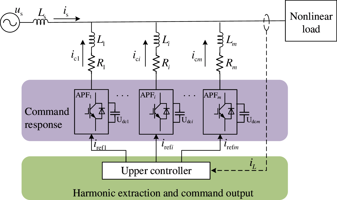
Figure 1: Basic topology of modular multi APF
The upper controller firstly detects and decomposes the iL, then gets the magnitude of the harmonic current iref to be compensated. Finally, the harmonic current size to be compensated by each APF is allocated reasonably through the instruction allocation strategy, so as to realize the optimal compensation of the harmonic of the power grid by multiple APF. The optimization strategy also needs to consider the specific parameters of a single APF. The basic structure of the single APF is shown in Fig. 2.
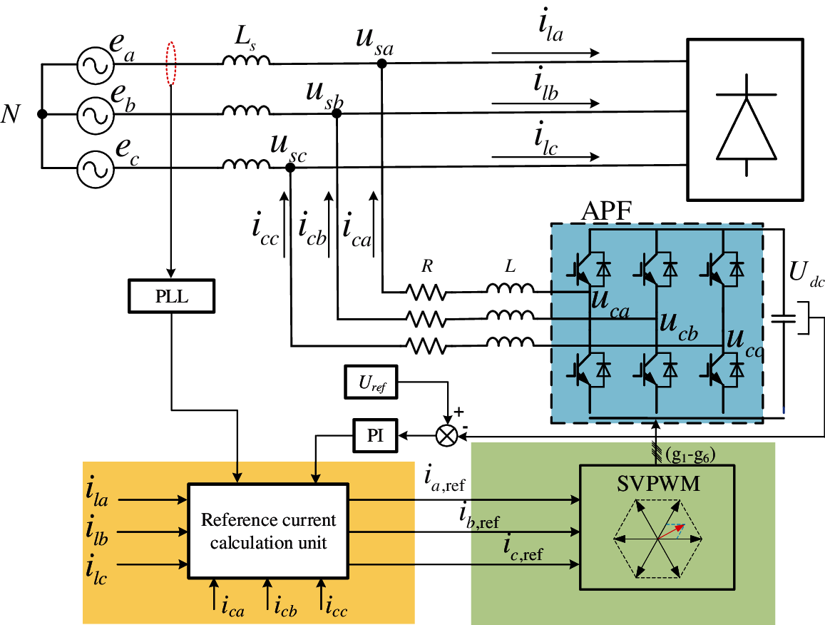
Figure 2: Single APF inner basic structure
According to the relation between Kirchhoff law and the circuit structure in Fig. 2, the relationship between voltage and current of APF can be obtained as equation:
where,
icj—the output current of j-phase APF
ucj—the output voltage of j-phase APF
usj—the j-phase grid voltage (j = a, b, c)
The Laplace transform of a phase is used to obtain the following results:
After formula (2) is sorted out, the transfer function between ica and (usa − uca) is as follows:
Obviously, the system can be treated as a first-order system. Assuming that the DC side voltage Udc of APF is constant during the sampling period, it can be treated as a step signal. In Eq. (3), it can be seen that in the dynamic performance index given by the system, the signal cannot reach the expected value quickly, and the inherent system error appears. In practical engineering applications, the loss of APF internal switching devices, PWM control and switching device's own error, etc., will cause the compensation current of APF cannot reach the expected value.
In addition, it can be obtained from Eq. (1) that reducing the equivalent inductance L of the equivalent APF can also improve the dica/dt, but if L is very small, the harmonic of APF based on the switching frequency characteristics will be very large, and once the APF itself has problems, it will produce a large over-current, which will affect the normal operation of the whole system. Therefore, for the compensation system composed of multiple APFs, it is necessary to ensure reasonable operation at the same time, reasonable optimization of the compensation current of each set is also the key.
2.2 APF Communication Network Topology
In the communication network, the network topology can be modeled by an undirected weighted graph G = (V, E, A), where V = {v1, v2,…, vn} is a non-empty finite set used to determine nodes, E ∈ V × V is used to represent the set of connected edge combinations between nodes in the network topology, and A = [aij]nxn is a weighted adjacency matrix and matrix composed of non-negative adjacency elements aij. Node index belongs to finite set N = {1, 2,…, n}. The vi represents the i-th node. The connection relationship between nodes in a graph is represented by eij = (vi, vj), and the adjacent elements associated with the graph are positive, that is, if and only if aij > 0, eij ∈ E. In addition, assuming aij = 0, if two different nodes of the graph can be connected along the edge of the graph, the graph is called undirected. The Laplacian matrix L = [lij]mxm of a graph is defined by the following formula (4):
3 Cooperative Control Strategy of Multiple APFs
3.1 Proportional Allocation Strategy of Compensation Capacity
For the cascade operation of multiple APFs, a two-way communication channel is established between the APF and the central controller through centralized control. The central controller first collects the information of the lower controlled object APF, so as to obtain the global information, and uses it to switch the APF and allocate the compensation capacity to realize the optimal coordinated control of the APF. Due to the real-time requirement of APF, the actual output of compensation capacity is realized by the controller of APF.
In order to make good use of the capacity of APF for harmonic current distribution, Yang et al. [14] proposed a strategy of proportional distribution according to the compensation limit (i.e., current sharing method). Under the condition that the capacity of APF may be different, assuming that m APFs operate jointly, and assuming that the compensation limit of APF is
KJp is the capacity proportional distribution coefficient of the p-th APF, which is defined as follows:
where
From the above analysis, the capacity allocation principle is based on the capacity of each APF participating in the compensation. The compensation capacity is allocated according to the proportion. At the same time, the cut-off current limiting method is used to control the switching and joint operation of APF. The capacity allocation of APF is carried out through Eq. (7), which makes full use of the capacity of each APF. However, this capacity allocation method does not make good use of the performance of each APF, and has the same effect. There is no communication between each other and the dynamic performance is lost.
3.2 Current Distribution Strategy Considering APF Performance
This paper considers the capacity of each APF and the performance of each APF when designing the algorithm. The performance here is mainly reflected in the harmonic compensation rate η of APF. When the load harmonic current is in the range of APF compensation current, the definition of the harmonic compensation rate η of each APF is as follows:
where,
Iref—the root means square value of ideal command current input to APF.
Ic—the difference between the actual root means square value of current output from APF and Iref.
The allocation of APF cooperative instruction current is to minimize the total harmonic distortion rate when the whole harmonic compensation system is running under a series of operation constraints. Because the algorithm needs to rely on the communication of neighbor nodes when using, the communication topology in this system is assumed to be a connected undirected graph. The capacity compensation allocation considering APF performance is proposed in this paper The basic form of strategy is as follows:
where,
ɛ is a performance weight adjusting factor, by adjusting the size of the factor to adjust the weight of the current allocated according to the performance in the allocated instruction current irefp, KXp is the performance distribution coefficient of the p-th APF, defined as:
where,
Because the communication topology is connected undirected graph introduced in the improved algorithm, the Laplacian matrix L in the algorithm satisfies 1TL = 0, so the following formula can be obtained:
Therefore, the sum of the performance compensation part in the formula is ultimately 0, that is, in the process of joint operation of multiple APFs, while improving the performance utilization of each APF, the relationship between the input and output of the whole APF system will not be broken. According to cooperative control theory [15], when the control system converges, the minimum requirement for communication topology is complete communication matrix sequence, which means that in the directed graph of communication network structure formed by L matrix, at least one node can reach globally, that is, the node can reach all other nodes along the direction of the path in the graph.
In practice, when the nonlinear load increases, or some types of faults occur in the common coupling point, the strong pulse current caused by these faults will be included in the instruction current, which will lead to the over-current fault of APF. In this paper, the truncated current limiting control strategy is adopted, so the truncated current limiting factor kp is introduced:
where,
kp—represents the current limiting factor of the p-th APF.
The final allocation strategy of APF capacity compensation can be obtained as follows:
where,
where
In Eqs. (13-1)–(13-7), it can be seen that the command current of each APF participating in harmonic compensation work in compensation supply is composed of two parts, namely, the capacity proportion distribution part and the capacity performance distribution part. Based on the proportional capacity allocation, the performance index of the i-th APF can be obtained by using the communication topology, and the capacity can be allocated twice according to the performance index, so as to improve the utilization of each APF in the system. The specific algorithm flow chart is shown in Fig. 3.
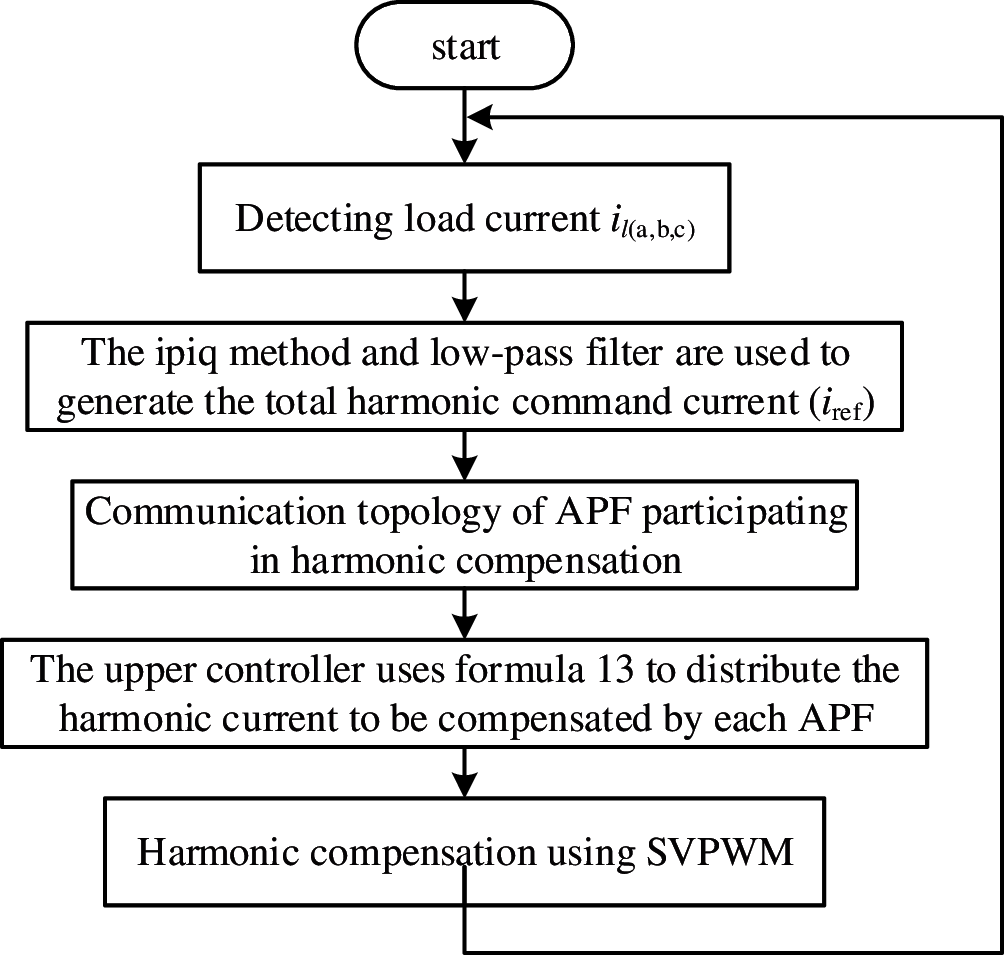
Figure 3: Flow chart of the algorithm proposed in this paper
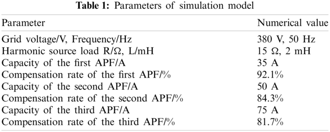
In order to verify the effectiveness and feasibility of the command power distribution strategy considering APF performance mentioned in this paper, the three-phase two-level active power filter is used for research. The model based on Fig. 1 is built by using simulation software, and the algorithm is analyzed with three-phase uncontrollable rectifier load as harmonic source. The specific parameters of the simulation model are shown in Table 1, and the performance of each APF in the table is as follows the harmonic compensation rate is obtained by simulation of APF. and the PI parameters of each APF for DC side voltage control are obtained by [16]. The control strategy of the inverter is SVPWM.
The first APF is used for harmonic compensation at PCC, starting at 0.04 s. The simulation waveform is shown in Fig. 3, and FFT analysis is performed by extracting a relative to it, as shown in Fig. 4.
It can be seen from Fig. 3 that although the capacity of a single APF has exceeded the capacity to be compensated, due to the limitation of the compensation performance of a single APF, when the current to be compensated is large, the APF current cannot quickly follow the harmonic current of the grid, resulting in a relatively large THD. In Fig. 4, it can be seen that the THD of a single APF after compensation is 14.11%. When the load changes suddenly, if there are no good PI parameters to support, single controller will not be able to achieve excellent anti-interference performance and smooth tracking performance. Therefore, three APFs are set to compensate the harmonic of the system again by using the current sharing method. The compensation waveform results are shown in Fig. 5. The compensated waveform is extracted from phase a for FFT analysis, as shown in Fig. 6.
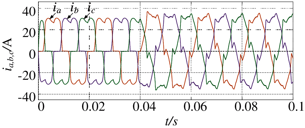
Figure 4: Harmonic compensation of single APF
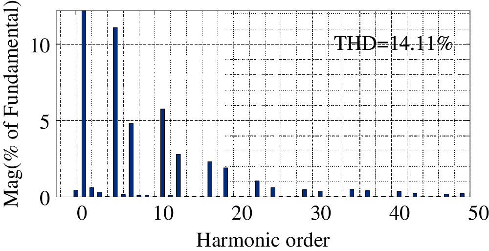
Figure 5: FFT analysis of harmonic compensation by single APF
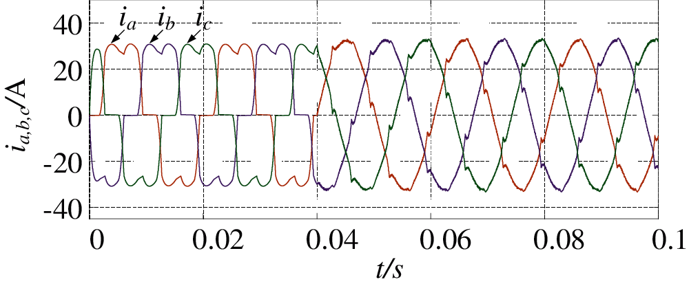
Figure 6: Harmonic compensation waveform of three APFs using current sharing method
It can be seen from Fig. 5 that with the increase of the number of APFs, the capacity of each APF with parameter compensation has been greatly improved. It can be seen from Fig. 6 that the THD of power grid current after three APFs with different capacity and performance compensate the power grid is 4.74%, which has been greatly reduced compared with that of single control. The total output compensation harmonic current of the combined APF is compared with the theoretical total output harmonic current, as shown in Fig. 7.
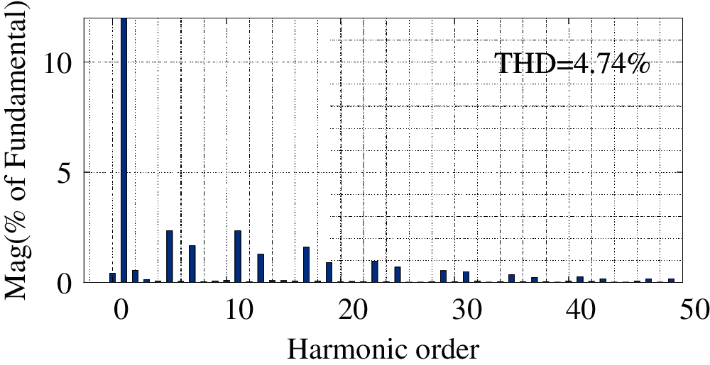
Figure 7: FFT analysis of three APFs after harmonic compensation with current sharing method
As can be seen from Fig. 7, the performance of each APF cannot be fully utilized because the performance of each APF is not considered, resulting in the weak harmonic following performance of the whole compensation system.
Therefore, the capacity allocation strategy of APF is improved by the method proposed in this paper. The communication connection is established for three APFs. The corresponding Laplace matrix L is:
Let
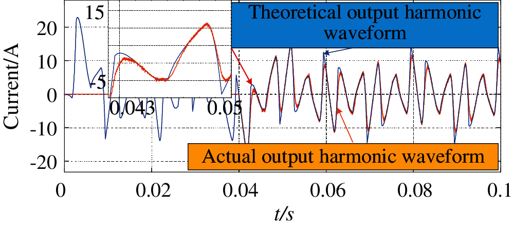
Figure 8: Three APF using the method of harmonic current compensation to follow
As can be seen from Fig. 9, compared with the current sharing compensation strategy, after considering the compensation performance of each APF participating in the compensation, the compensated waveform is smoother. As can be seen from Fig. 10, the THD of the power grid compensated by this strategy is 1.85%, because the compensation result is more effective after using this strategy. The performance of APF is improved obviously. Compared with the traditional strategy, this strategy has a good response speed to the sudden change of grid harmonics.
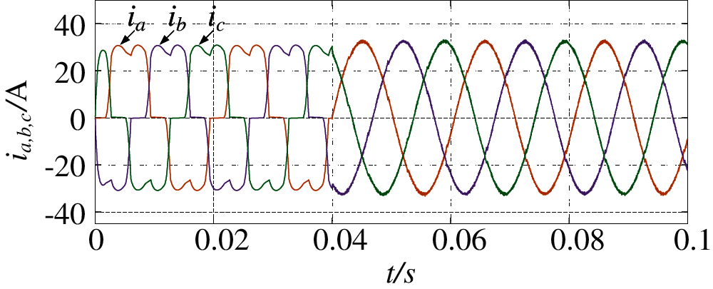
Figure 9: Harmonic compensation waveform of three APFs using improved algorithm
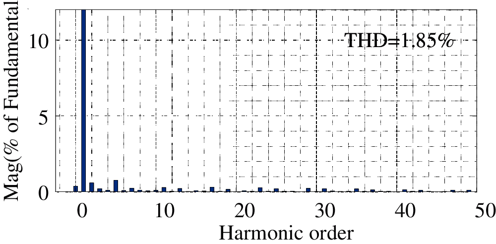
Figure 10: FFT analysis of three APFs after harmonic compensation using improved algorithm
In order to judge the following situation of the improved strategy, continue to compare the total output compensation harmonic current of the combined APF with the theoretical total output harmonic current, as shown in Fig. 11. It can be seen that compared with Fig. 8, because the improved method considers the performance of each APF, the harmonic following performance has been greatly improved.
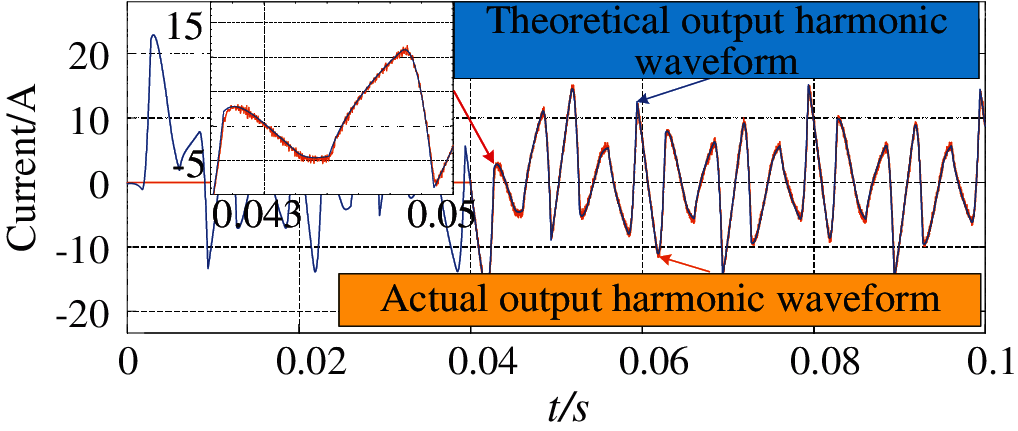
Figure 11: Three sets of APF using improved algorithm for harmonic compensation to follow
The capacity compensation capacity can be expanded by using multiple APF cascades, and the capacity can be allocated to each APF which is involved in harmonic compensation. The capacity coordination allocation compensation scheme considering the performance of APF is proposed in this paper. The performance of each APF is considered while the capacity proportion compensation is considered. The feasibility of the scheme is confirmed by stability analysis and simulation results analysis Sex. The simulation results show that the compensation capacity of cascade APF is improved without changing the installation capacity.
Funding Statement: This work was supported in part by the National Natural Science Foundation of China (Grant No. 61863023).
Conflicts of Interest: The authors declare that they have no conflicts of interest to report regarding the present study.
1. Li, H., Liu, Y., Yang, J. (2021). A novel FCS-MPC method of multi-level APF is proposed to improve the power quality in renewable energy generation connected to the grid. Sustainability, 13(8), 4094. DOI 10.3390/su13084094. [Google Scholar] [CrossRef]
2. Wang, X., Blaabjerg, F. (2019). Harmonic stability in power electronic-based power systems: Concept, modeling, and analysis. IEEE Transactions on Smart Grid, 10(3), 2858–2870. DOI 10.1109/TSG.2018.2812712. [Google Scholar] [CrossRef]
3. Huang, W., Dong, X., Lei, J., Yu, L. (2016). Analysis on comprehensive influence of large capacity distributed photovoltaic grid connection on distribution network. Proceedings of the CSU-EPSA, 28(11), 44–49. DOI CNKI: SUN: DLZD.0.2016-11-008. [Google Scholar]
4. Li, M., Wang, Z., Wang, Y.,Xue, J., Wang, L. (2014). Research on shunt active power filter without harmonic detection. High Voltage Apparatus, 50(10), 73–77. DOI 10.13296/j.1001-1609.hva.2014.10.037. [Google Scholar] [CrossRef]
5. Zhuo, F., Yang, Z., Yi, H.,Yang, G., Wang, M. (2020). Optimal allocation strategy of control equipment for comprehensive distribution network harmonic wave and three-phase unbalance evaluation index. Electric Power, 53(11), 40–49. [Google Scholar]
6. Xu, Y., Xiao, X., Liu, H., Wang, H. (2005). Parallel operation of hybrid active power filter with passive power filter or capacitors. IEEE/PES Transmission & Distribution Conference & Exposition, pp. 1–6. Asia and Pacific, Dalian, China. [Google Scholar]
7. Wang, T., Hou, Y., Li, D., Yao, J. (2020). Research on high-voltage and large-capacity active power filter for intermediate frequency induction furnace. 23rd International Conference on Electrical Machines and Systems, pp. 390–394. Hamamatsu, Japan. [Google Scholar]
8. Wang, X., Gao, Y., Lin, L., Song, J., Lu, S. (2019). Research current status and prospects of active power filters. Power System Protection and Control, 47(1), 177–186. [Google Scholar]
9. Li, Z., Hu, T., Du, Y.,Xiang, X., Zhang, T. (2020). An optimized window function and its application in harmonic detection of power grid. High Voltage Apparatus, 56(10), 239–252. DOI 10.13296/j.1001-1609.hva.2020.10.037. [Google Scholar] [CrossRef]
10. Ma, L., Wang, X., Wang, Y., Wang, Y. (2013). Research on intelligent detection method of APF specific harmonics. Control Engineering of China, 20(2), 352–356. DOI 10.14107/j.cnki.kzgc.2013.02.016. [Google Scholar] [CrossRef]
11. Piao, Z., Zhong, Y. (2018). Harmonic compensation control of grid-connected inverter based on virtual impedance. 21st International Conference on Electrical Machines and Systems, pp. 2364–2368. Jeju, Korea (South). [Google Scholar]
12. Liu, Y., Tang, G. (2013). Application of specific order harmonic compensation algorithm based on improved adaptive phase locked loop in APF. Transactions of China Electro Technical Society, 28(5), 259–264. DOI 10.19595/j.cnki.1000-6753.tces.2013.05.036. [Google Scholar] [CrossRef]
13. Jin, Y. (2019). A novel harmonic control method for MMC combining improved nearest level control and selective harmonic elimination method. IEEE Energy Conversion Congress and Exposition, pp. 6368–6375. Baltimore, MD, USA. [Google Scholar]
14. Yang, Z., Zhao, J., Tang, G. (2006). Joint compensation coordinated control of multiple parallel APF. Proceedings of the CSU-EPSA, 17(6), 32–37. [Google Scholar]
15. Qu, Z. (2009). Cooperative control of dynamical systems. London: Springer. [Google Scholar]
16. Marcu, M., Popescu, F., Niculescu, T., Pana, L., Handra, A. D. (2014). Simulation of power active filter using instantaneous reactive power theory. 16th International Conference on Harmonics and Quality of Power, pp. 581–585. Bucharest, Romania. [Google Scholar]
 | This work is licensed under a Creative Commons Attribution 4.0 International License, which permits unrestricted use, distribution, and reproduction in any medium, provided the original work is properly cited. |