| Energy Engineering |
DOI: 10.32604/ee.2022.018160
ARTICLE
Impacts of Rotation on Unsteady Fluid Flow and Energy Distribution through a Bending Duct with Rectangular Cross Section
1School of Mechanical and Mechatronic Engineering, University of Technology Sydney, Ultimo, NSW 2007, Australia
2Department of Mathematics, Jagannath University, Dhaka, 1100, Bangladesh
*Corresponding Author: Suvash C. Saha. Email: Suvash.Saha@uts.edu.au
Received: 04 July 2021; Accepted: 17 September 2021
Abstract: A depth understanding of fluid flow past a curved duct having rectangular cross-section with different aspect ratios (l) are essential for various engineering applications such as in chemical, mechanical, bio-mechanical and bio-medical engineering. So highly ambitious researchers have given significant attention to study new characteristics of fluid flow in a curved duct. The flow characterization in the rectangular duct has been studied over a wide range of numerical and selective experimental studies. However, proper knowledge with the effects of Coriolis force for different aspect ratios is important for better understanding of the transitional behaviour and the subsequent heat generation, which is required to improve further. The purpose of this study is to reveal insight into the transitional flow pattern and heat transfer in a curved rectangular domain. The Navier-Stokes equations are solved using the spectral method, while the Crank-Nicolson method is used to solve the energy equation. An in-house FORTRAN code is developed to get the numerical solution. For post-processing purposes, Tecplot-360 and Ghost-script tools are used. The present study exposes development of Dean vortices that affect heat generation as well as thermal enhancement in the flow with underlying the flow controlling parameters, the Dean number (Dn), the Grashof number (Gr) and the Taylor number (Tr). Time-dependent results followed by phase spaces show that transient flow undergoes in the scenario ‘chaotic
Keywords: Aspect ratio; dean flow; heat generation; rotating duct; transient flow
Nomenclature
| Angular velovity : | Ω |
| Prandtl number : | Pr |
| Aspect ratio : | l |
| Phase space : | γ |
| Axial flow direction : | z |
| Pressure : | P |
| Coefficient of thermal diffusivity : | α |
| Pressure gradient : | G |
| Coefficient of thermal expansion : | β |
| Radius of the curvature : | L |
| Curvature of the duct : | δ |
| Resistance coefficient : | λ |
| Dean number : | Dn |
| Sectional stream function : | ψ |
| Density : | ρ |
| Taylor number : | Tr |
| Free stream velovity : | U0 |
| Temperature : | T |
| Grashof number : | Gr |
| Thermal diffusivity : | κ |
| Gravitational acceleration : | g |
| Time : | t |
| Half-height of cross-section : | h |
| Velocity along x-direction: | u |
| Half-width of cross-section : | d |
| Velocity along y-direction : | v |
| Kinematic viscosity : | ν |
| Velocity along z-direction : | w |
| Nusselt number : | Nu |
Rotating flow and consequent heat conduction through the curved duct have been drawn considerable interest to the researchers for their vast applications not only in the field of fluids engineering (cooling and heating systems) and aviation engineering [1] but also in biomedical engineering, for instance, inertial based cell separation [2,3]. In practice, rotating thermal flux frequently occurs in a variety of rotational setups. A wide range of studies [4–8] has been conducted to analyze the flow and heat transfer for the rotational/non-rotating domain.
In a curved duct, centrifugal force is produced due to the duct’s curvature, resulting in a lateral rotating vortex acting in the axial direction. In the bending domain, these vortices have the properties of spiraling motion known as secondary flow [9–12]. These vortices are a pair of additional counter-rotating vortices that form on the duct’s external hollow surface [13–16]. A wide range of theoretical/numerical studies [17–20] and limited experimental [21–23] studies were conducted to analyze the flow characteristics and formation of the Dean vortices for curved ducts. The mismatch of the primary and secondary flows due to the centrifugal and Coriolis forces in the rotational bent duct influences the fluid flow and generates Dean vortices. These outcomes of rolling either increase or decrease in nonlinear mathematical features of flow that rely upon the instability of heat flux and the streaming region. Yanase et al. [24] performed spectral analyhsis of laminar flow through a stationary curved duct over a wide of aspect ratio (1 ≤ l ≤ 12). The investigation was performed to analyse the steady solution with the help of Newton-Rapson method employing symmetry flow condition. They obtained five branches of steady solutions and examined linear stability of the solutions. Chen et al. [25] performed a bifurcation study of the flow passing through a bent tube with increasing Dn and aspect ratio (Ar), where two types of bifurcations depending on the range of Ar were observed. Recently, Hasan et al. [26] applied a spectral-based numerical technique to investigate the critical points considering stationary and non-stationary bent square duct flow. In continuation of this study, very recently, Chanda et al. [27,28] investigated the effects of heat-flux and curvature ratio on fluid flow and thermal distribution in a bent rectangular duct maintaining a temperature difference between the horizontal walls using the method that was used by Islam et al. [29]. The study investigated the flow scenario over a wide range of the curvature (0.001 ≤ δ ≤ 0.5) for both co-rotating and counter-rotation of the system and noticed 2- to 11-pair of vortices. Effects of curvature on secondary vortices were also obtained and displayed in the bar diagrams. Wang et al. [30] demonstrated a bisectional inspection on the flow past in a circular tube, and the study applied a finite volume scheme for flow characterization. Most of the studies, available in literature, have been conducted for small Dean numbers that investigated the flow characteristics and temperature distribution through a bent square or rectangular-shaped duct for small pressure gradient force. However, bifurcation structure as well as flow transition and energy distribution through a bent rectangular duct considering a significant temperature difference between the vertical walls with combined effects of Coriolis and centrifugal forces is less performed, which attracts the authors to fill up this gap.
Time-dependent solution structures of the fully developed flow were investigated first by Yanase et al. [31] for the curved rectangular duct. The study reported the time-dependent results, where both steady and unsteady solutions subsisted together. Very recently, Dolon et al. [32] developed a computational model on curved rectangular duct flow and investigated the combined effects of centrifugal and heating-induced buoyancy instability of the flow where this investigation built up a relationship between the flow velocity and isotherms. Impacts of Dean vortex on overall heat transfer were also shown. Nobari et al. [33] investigated the three-dimensional computational analysis of incompressible real fluid and heat transference through a U-type square channel. The author found that the centrifugal force due to curvature is dominating over coriolis force in bending region, while the opposite results were observed in straight part of the duct. Most of the previous studies focused on rotating geometries with small pressure gradient, and researchers did not give much attention to investigate effect of high Dean number in the steady or transient solution along with the number of secondary near-wall vortices for increasing or decreasing the rotation. The effect of high pressure gradient on fluid flow through a rotating curve rectangular-shaped duct is not considered though it has huge applications in engineering approach. Hence, motivated from these unresolved issues, the present paper investigates fluid characteristics for high pressure gradient with simultaneous change in system rotation and aspect ratio because flow instability and heat transfer enhancement is certainly affected by the high gyration with strong pressure gradient force applied along the centre-line of the duct.
One of the most features of fluid flow over a curved channel is heat conduction between two walls. Dean flow can help to transport energy and consequently increase heat transfer between two side walls. Chandratilleke et al. [34] showed the effect of aspect ratios (starting from 1 to 8) on convective heat transfer through the curved rectangular duct without considering the rotational effects. The authors compared their findings with the experimental study and found good agreement. Mondal et al. [35] performed a non-isothermal analysis for square channels and observed Dean flow to enhance heat conduction. Norouzi et al. [36] investigated the inertial and creeping motion for 2nd-grade fluid to analyze the stress and heat transfer in a curved channel by employing the finite difference scheme. They observed that heat transfer was dominated by the normal stress difference for the viscoelastic fluid. Centrifugal force and curvature of the outlet were yielding the first two regular stress varieties in the flow region.
The hydro-thermal efficiency of coupled rotating cylinders with partially porous system in the bifurcation duct was investigated by Kolsi et al. [37] using the finite element method and hybride nanofluid as the working fluid. They found that the distribution of heat energy of distinct hot wall portions varied depending on the cylinders’ Reynolds number and rotational speed, which intensify the heat transfer nearly 25% compard to non-rotation cylinder. Another study was conducted by Selimefendigil et al. [38] on rotating adiabatic circualr cylinder with the help of Galerkin weighted residual finite element method to understand convective heat trnsfer by CNT-water nanofluid. The numerical findings showed that the rate of heat enhancement of the cylinder was dependent on the rotational speed and nondimentional tarbulance parameter (Richardson number). They also found that the mean heat transfer coefficient was calculated to be low computational cost with higher accuracy compared to high fidelity of 3D intensive CFD calculation.
Alsabery et al. [39] applied FEM and Arbitrary Lagrangian-Eulerian numerical procedure to investigate transient entropy and mixed convection in a cavity with flexible wall. They validated their computational code using the previous data. The results revealed an essential impact of the elastic modulus on the flow and heat transfer in the fluid. Recently, Hasan et al. [40] performed numerical simulation with convective heat transfer through a rotating bent square duct for various curvatures. The authors discussed the steady and unsteady solutions with linear stability and found that secondary flow enhances heat transfer significantly, and the chaotic flow, which occurs at large Dn’s, enhances heat transfer more efficiently than the other unsteady solution. Very recently, Chanda et al. [41] investigated the convective heat transfer and fluid flow, and they clearly showed that the convective heat transfer is significantly enhanced by the secondary flow and the chaotic solutions enhance heat transfer more effectively than the steady-state or even periodic or multi-periodic solutions. As par authors’ knowledge, very little research has been conducted on the time-dependent flow characteristics through a curved channel caused by the development of buoyancy-induced centrifugal-Coriolis instability with rotational effects, and the impact of rotation on convective heat transfer is not much studied. On the other hand, the temperature difference between the walls affects in changing fluid density, which eventually creates buoyancy instability the curved channel. Considering this issue importantly, the present study shows how Dean vortices are produced at the outer concave wall and how it contributes to developing and transferring heat in the bending duct as the system is rotated in the positive direction. The present investigation, therefore, demonstrates to fulfil this research gap on curved channel flows. From the engineering standpoint, it is essential to analyse such type of flows as it is often faced in engineering applications. The present study also reports the transient behaviour of real fluid past a bent rectangular channel having aspect ratios 2 and 3 by employing a numerical algorithm and elucidate an increase of heat flow by the secondary and axial flow distribution.
2 Model Development and Numerical Calculation
In a fixed orthogonal coordinate system, the unsteady flow of an incompressible Newtonian fluid in a curved pipe with fixed curvature is studied. A rectangular shape cross-section is considered, where the height and width are 2h and 2d, respectively, and maintaining the various aspect ratios (l = h/d). The geometry with the corresponding notations has been illustrated in Fig. 1. The coordinates of x′ and y′ axes have been considered the base components and z′ axial flow direction. The whole arrangement revolves at a constant spinning velocity
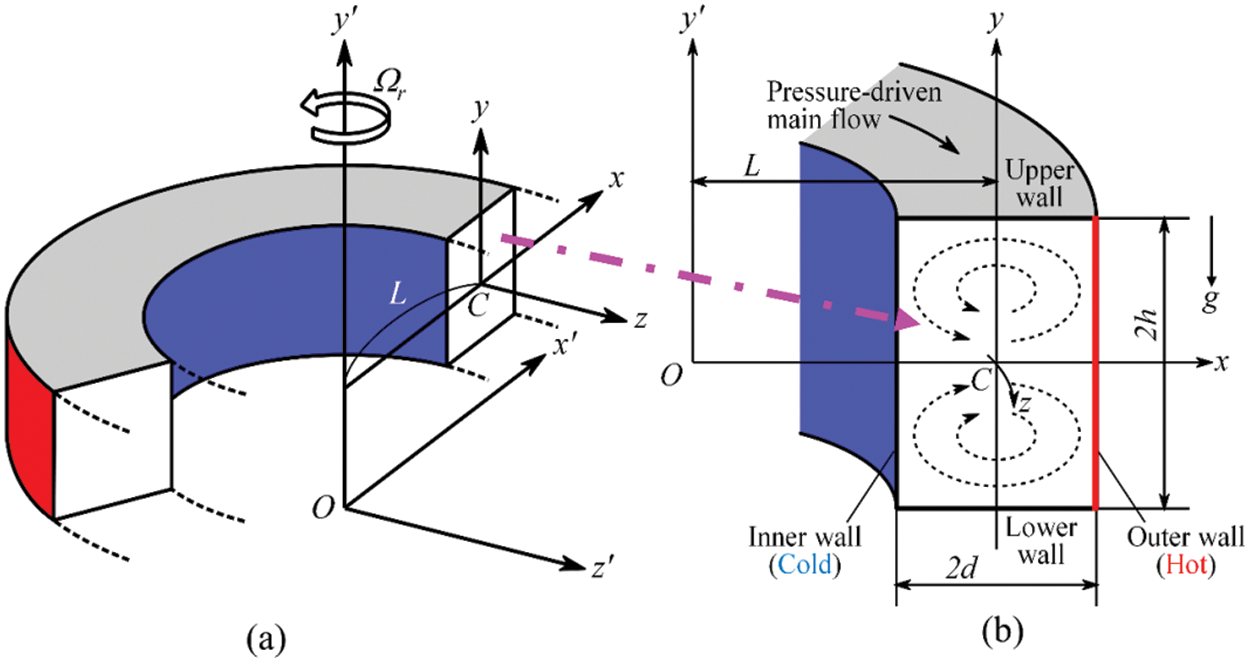
Figure 1: (a) Schematic coordinate system of the model and (b) Cross-sectional view of the duct
All the dimensional quantities are converted into the non-dimensional component by employing the representative length (d), the representative free stream velocity (U0 = υ/d), and representative time (t = d/U0 = d2/υ), where υ is the kinematic viscosity. The velocity vectors (u, v) along horizontal (x), vertical (y) are being dimensionless by U0, and w for axial (z) directions by √(2δ)/U0, where δ = d/L is known as curvature of the curved pipe. The non-dimensional temperature and pressure are obtained from the transformation by T = T/∆T and ρU02 = P/P, respectively. Hereafter, all the variables are dimensionless, if it is not specified. The flow field is taken to be homogeneous along the axial path; the single-stream function
A unique variable
where,
The dimensionless parameters
where, G be the pressure gradient, μ be the dynamic viscosity, α be the coefficient of thermal diffusivity, β be the coefficient of thermal expansion, g be the acceleration due to gravity, and λ be the resistance coefficient. The flow patterns are monitored with varying the rotational parameter (Tr) for two different aspect ratios (l = 2, 3), and the other flow controlling parameters (Dn = 1500, Gr = 500, δ = 0.1, Pr = 7.0) are kept constant. The given boundary conditions employed in this study for w,
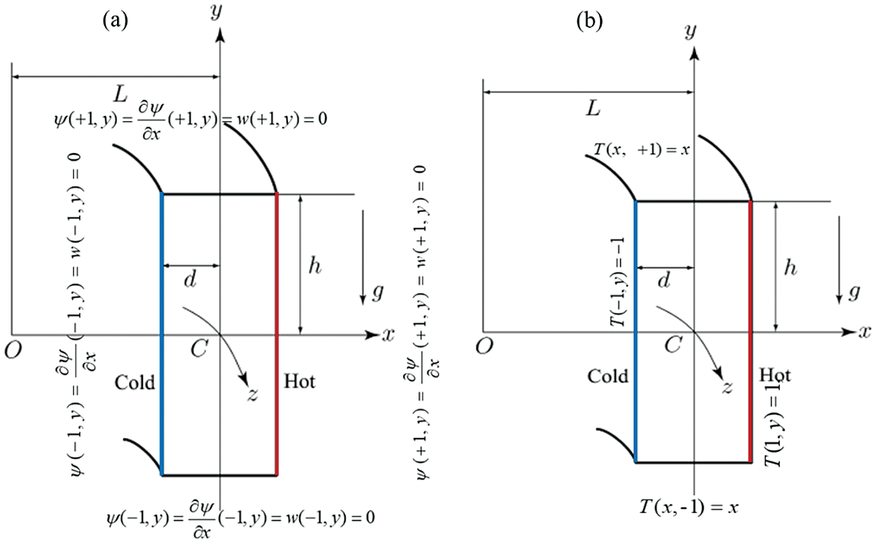
Figure 2: (a) Boundary conditions for axial flow (w) and secondary flow (
The governing Eqs. (2) to (4) have been solved by using the spectral method with boundary conditions (stated in Fig. 2) numerically. It may consider as a better approach to solve the Navier-Stokes equation together with heat conduction equations (Gottlieb et al. [42] because the variables have presented in a class of functions (Known as Chebyshev polynomials). The functions
where,
where
where
For evaluating the time-dependent results, both Crank-Nicolson and Adams-Bashforth schemes with Eq. (4) are then driven.
2.1 Model Validation and Grid Dependency Test
Before starting the investigation, the proposed model was validated comprehensively with published numerical modeling conducted by Mondal et al. [19]. Our model with numerical results are verified as shown in Fig. 3. The code was carefully developed for our model to optimize the flow conditions with geometrical configuration by adjusting the flow controlling parameters. Fig. 3 compares the averased Nu as the function of Dean numner at heated and cooled sidewalls of the channel. The general trend of Nusselt number concerning the corresponding Dean number consistently up surging with minimal fluctuation and agrees with numerical (Mondal et al. [19]) results. At the lower temperature wall, the calculated Nu from both studies show excellent agreement, whereas at high temperature wall, the present model produces lower Nu than Mondal et al. [19] findings but maintain the increasing trend of Nu. This discrepancy maybe for unknown cause of the model as the code was optimize as close as possible with Mondal et al. [19] study, which does not interfare the solution substabtially. For more validation, the present result is compared with Yamamoto et al. [43] and Chandratilleke’s [34] findings, as presented in Fig. 4. The author conducted an assay using the visualization method of flow with a curved rectangular duct for the non-rotation case by keeping l = 2 and considered air as a working fluid to generate the primary flow and smoke as a flow indicator captured as a flow indicator cross-sectional view of Dean vortex patterns. The number of vortices of the numerical finding is the same containing some distorted streamlines. Fig. 4c also displays the non-isothermal laboratory finding (for l = 4) by Chandratilleke et al. [44]. The results of the present simulations are more in line with the laboratory inspection in both quantitative and qualitative manner.
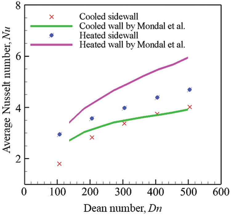
Figure 3: Comparison of averaged Nusselt number as the function Dean number from present study with numerical findings conducted by Mondal et al. [19]
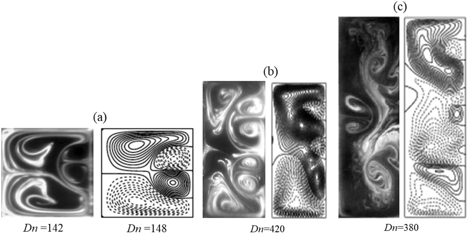
Figure 4: Comparison of secondary flows between experimental (left) and numerical (right) results. (a) Experimental result for rotating bend square duct flow (Tr = 150) by Yamamoto et al. [43] (left), (b) Chandratilleke [34] (left) for aspect ratio, l = 2 and (c) Chandratilleke et al. [44] (left) for aspect ratio, l = 4
The speed of rotation of the duct affects heat transfer through the Nusselt number. In order to measure the effect of rotation on heat generation, the Nusselt number was calculated and compared with the experimental results conducted by Becker et al. [45] and computational findings by Dallil et al. [46], as shown in Fig. 5. As the speed of the rotation of the system increases, the calculated Nusselt number is increasing. The Nusselt number from the present model lies between the experimental and computational results with some discrepancies. The maximum fluctuations were determined 14.63% and 7.32% for experimental and computational results, respectively, that lie in an acceptable range. Based on this comparison, the present model could be considered a well-validated model and could reproduce the best outcomes. After the model validation, the exactness of the numerical solution is tested by employing the grid dependency analysis. To establish the verification of the numerical results, taking
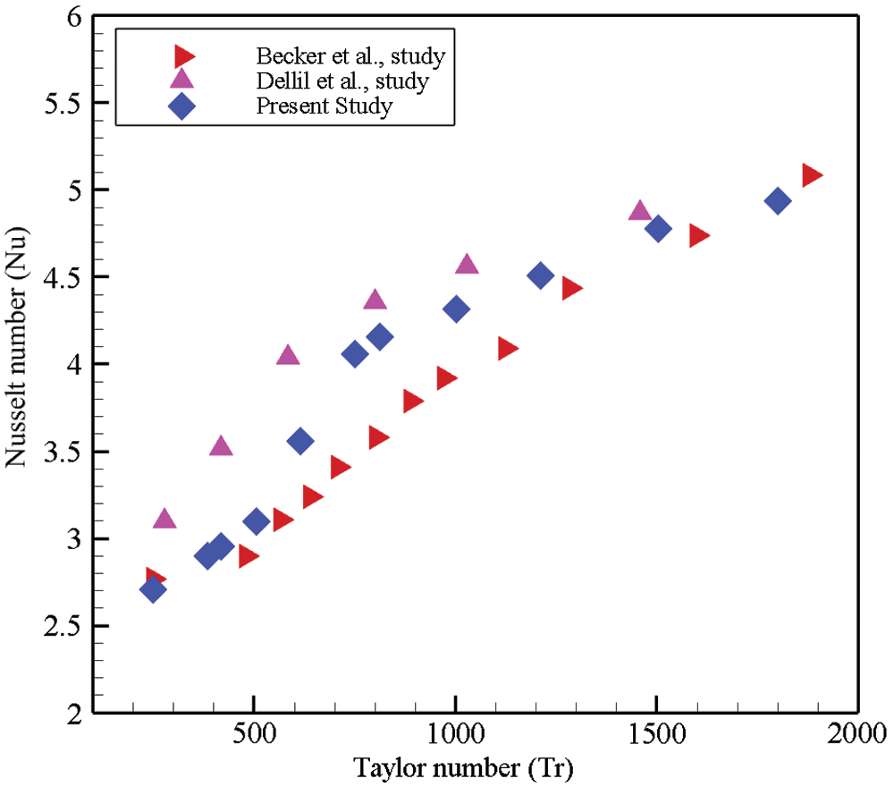
Figure 5: Comparison of Nusselt number as a function of Taylor number from experimental finding by Becker et al. [45] and numerical result by Dallil et al. [46] with the data from the current study
3.1 Time Evolution Calculation of the Solution
To explore the effect of Tr on the nonlinear behavior of the time-dependent solution, the time evaluation results have been investigated for
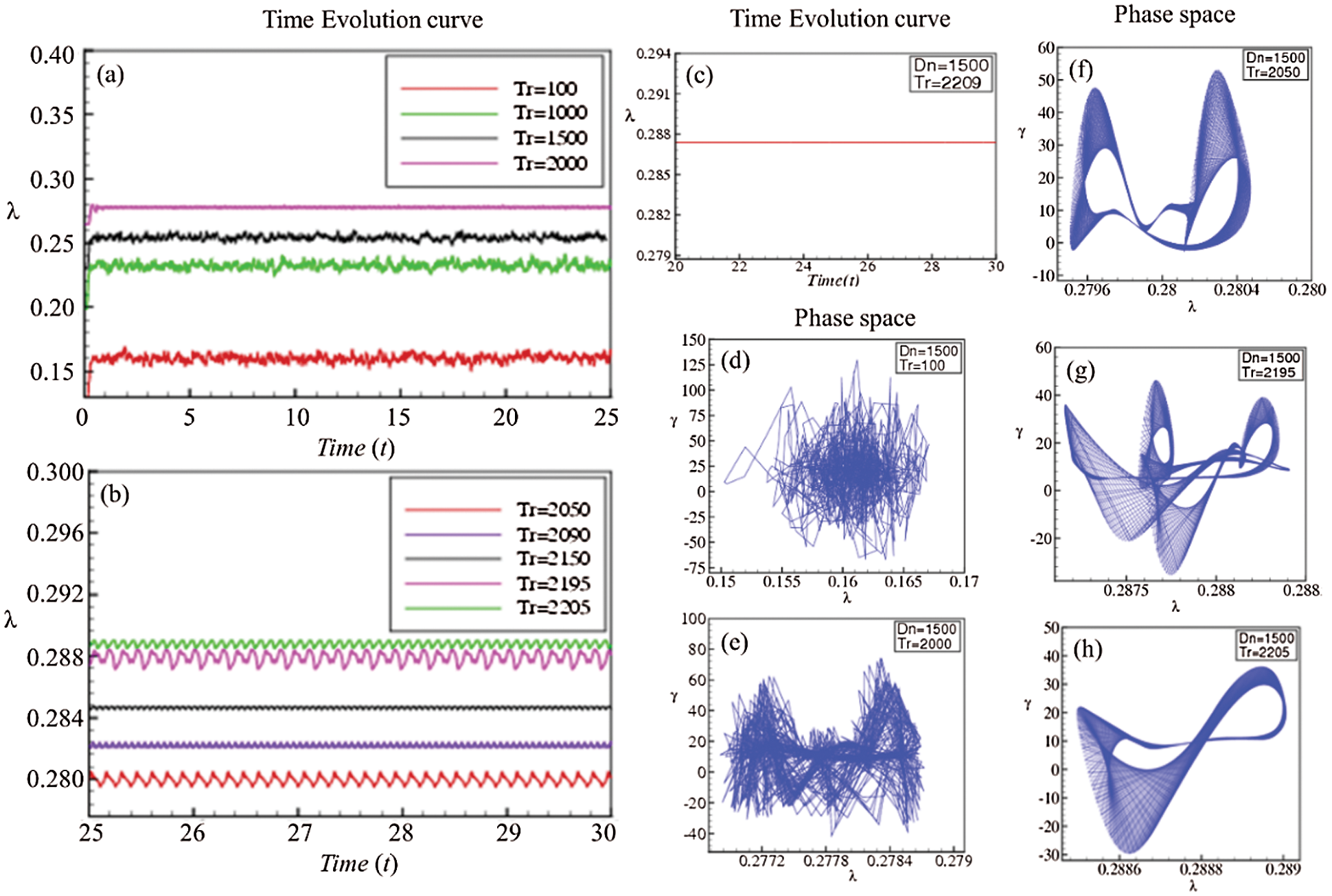
Figure 6: Time-dependent solution at Dn = 1500 for various Taylor number (Tr); time evolution data (a–c) and phase space diagram (d–h) for l = 2
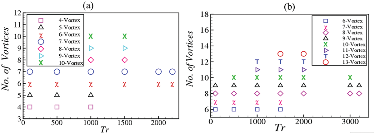
Figure 7: The vortices generation as a function of Taylor number (Tr) at Dn = 1500 and Gr = 500 for (a) aspect ratio l = 2 and (b) aspect ratio l = 3
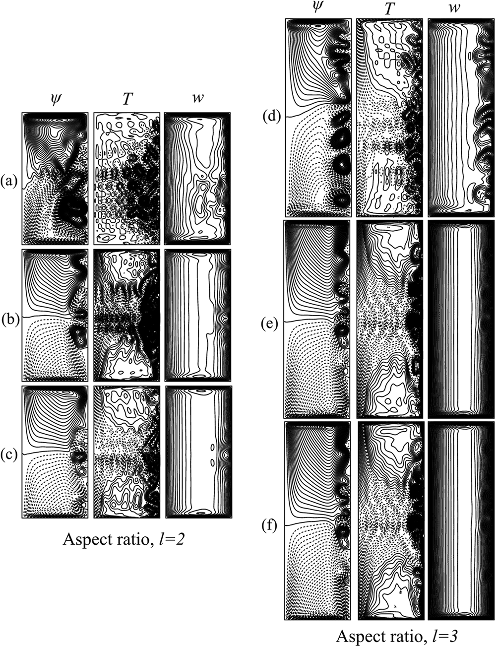
Figure 8: Secondary vortex structure for various Tr at Dn = 1500 and Gr = 500. The contours are displayed for (a, d) chaotic solution (Tr = 1000 for aspect ratios 2 and 3), (b, e) Periodic or multi-periodic solution (Tr = 2050 for l = 2 and Tr = 3150 for l = 3) and (c, f) steady solution (Tr = 2209 for l = 2 and Tr = 3195 for l = 3)
After a certain rotational speed, the time evolution curve will shift into the periodic or multi-periodic oscillating flow. The flow patterns are irregular in shape, while the oscillation and amplitude of the oscillation are lower than low rotational speed (Tr = 100). So before shifting into a periodic or multi-periodic flow, the time evolution curve does not follow any patterns, which reveals that the flow is transient chaos. The phase space diagram indicates the flow beats are still distorted, and it confirms that the flow is indeed the prediction for Tr = 2000. The orbit of the oscillation is going to become a shape like multi-periodic or periodic oscillation as Tr becomes larger. The time-dependent solution forms a patchy five-vortex configuration, where isotherms are consistent with the vortex structure. The formation of an extra pair of vortices is primarily separated from the flow in a duct having slight curvature; at low
3.2 Heat Transfer Through Vortex Generation
Nusselt number (Nu) is considered as the ratio of convective to conductive heat transfer across the boundary of the channel wall. It mainly describes the heat transfer in the boundary surface within the domain. Mathematically it can be written as
where
Note that, if the fluid free-stream temperature and the wall-surface temperature vary, a thermal boundary layer develops near the vicinity of the wall and due to the energy exchange resulting from the temperature variation between the walls, a temperature profile is formed. As a temperature difference between the outer and inner walls is applied, a thermal boundary layer is developed for both heated and cooled walls, which contributes to the characterise the flow nature. To measure such nature of the unsteady fluid flow for the steaming motion in the bending channel Eqs. (12) and (13) are employed.
The calculated values of the time-averaged Nusselt number (Nu) are plotted in Fig. 9 for aspect ratios 2 and 3 (l = 2, 3) and time evolution calculation of inner and outer bend of the duct at several magnitudes of the rotational parameter (Tr) has been considered to find the time-averaged of Nu. The Nusselt number at different rotational parameters (Tr) has been illustrated. The symbol indicated by a circle (red color) demonstrates the index of heat conduction along the heated sidewall, whereas the symbol with the circle (blue color) reveals the rate of heat transfer in the cooled bending wall at aspect ratio 2. The calculated Nu for both heated and cooled surfaces shows almost the same trend that describes the increasing hot wall energy shifting rate increases gradually. For the outer bending wall, Nu has been found ranging 2.92 ≤ Nu ≤ 3.28 within the flow domain, whereas for the inner wall, the value is observed for 1.63 ≤ Nu ≤ 1.98 at l = 2. On the other hand, for aspect ratio 3 (l = 3), the heated wall Nu has been noticed ranging 2.58 ≤ Nu ≤ 3.76 but for the cooled wall 1.54 ≤ Nu ≤ 1.95. The overall scenario is that the low aspect ratio dominates heat generation over large aspect ratio for all Tr at the cooled sidewall and for Tr ≤ 1000 at the heated wall. In contrast, the opposite effect is observed if rotational speed exceeds (Tr ≥ 1000) for the heated sidewall. It is found that the unsteady flow is periodic/multi-periodic for 2000 ≤ Tr ≤ 2205 when l = 2 and in 3100 ≤ Tr ≤ 3195 when l = 3; chaotic for 0 ≤ Tr < 2200 for l = 2 and in 0 ≤ Tr < 3100 for l = 3. Yanase et al. [47] and Mondal et al. [35] showed that periodic/multi-periodic and chaotic solution enhances heat transfer most effectively where Nu is higher, and this happens for l = 2 in the present case for Tr ≤ 1000. Actually, Nu is higher as Tr becomes large (Tr > 1000) for aspect ratio 3 than aspect ratio 2. The most significant findings are the gradual increase of Nu at the low and the high-temperature walls. The upsurge of this temperature is occurred because of the effect of the rotational parameter to maintain the constant heat flux (for cooling wall Qc = 671.23 Wm-2 and for heating wall Qh = 819.74 Wm-2). It is also mentioned that the variation of viscosity at the cooling bending wall is dampening the secondary flow and the vortex construction due to the energy gradient between these two side walls. Along the vertical centerline, the temperature management of fluid contributes to altering the density of the fluid due to the heated wall, and the fluid gets accelerated to travel. Consequently, heat is transferred to the low-temperature region. The rate of temperature distribution on the flow domain is analyzed to get a clear insight about the advection of the curved channel, as presented in Fig. 8. The inner bend's heat flux is lower than the outer bending wall, which validates our computational results. In order to isolate this effect, the temperature gradients at both the colled and heated sidewalls have been analyzed that has been discussed explicitly in the next section.
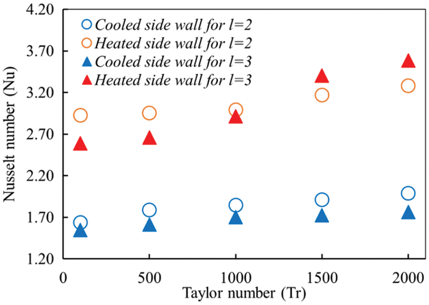
Figure 9: Variation of time average Nusselt at the inner and the outer bending walls of the channel concerning the Taylor number at aspect ratio l = 2, 3
3.3 Temperature Gradient Analysis
The temperature distribution of the outer and inner walls has been analyzed by calculating the temperature gradient of the flow domain (see Fig. 10) along the vertical axis. Convective heat flux at heating and the cooling walls illustrate various rotating speeds at the channel aspect ratio l = 2 and 3. The general trend of the temperature gradient
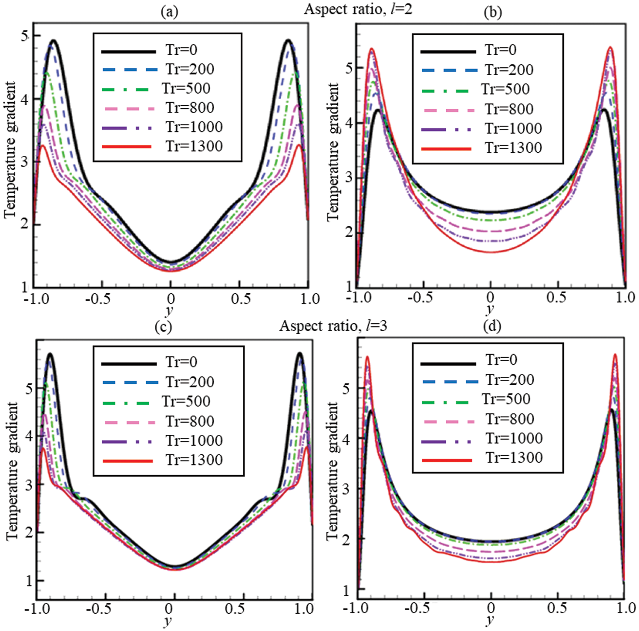
Figure 10: Temperature gradients (TG) for 0 ≤ Tr ≤ 1300 at Dn = 1500 and Gr = 500. (a) TG for l = 2 at the cooled wall (b) TG for l = 2 at the heated wall. (c) TG for l = 3 at the cooled wall (d) TG for l = 3 at the heated wall
The present computational study has been performed to characterize fluid flow and energy distribution through a rotating bent rectangular channel of aspect ratio 2 and 3. The effect of rotational parameters on fluid flow for a constant pressure gradient is investigated by analysing Dean-vortex formation, temperature contour, and axial flow distribution for low to high-speed of rotation. The numerical code has been developed to optimize the present model by validating existing experimental and computational studies, and found excellent agreement. The overall calculation is performed for a variable wall temperature, and an adiabatic condition is employed at the upper and the lower walls of the bending channel. The following conclusions have been drawn from the present study:
• Time-dependent solutions followed by phase-space analysis of the solutions exhibit that the transitient flow endures in the scenario ‘chaotic
• The numerical results report that maximum 10-vortex solution is attained for aspect ratio 2, while 13-vortex for aspect ratio 3. The study shows that 6- to 10-vortex solutions are available for the periodic solution, while 5- to 13-vortex for the chaotic solution. The chaotic regime of the flow exhibits maximum number of Dean vortices.
• The study illustrates that higher temperature difference occurs for lower Tr, while lower temperature difference for higher Tr.
• Gradual increase of the Nusselt number at the high and low temperatured walls happens because of the effect of Coriolis force to maintain the constant heat flux into the computational domain.
• The current study shows that there arises a strong interaction between the heating-induced buoyancy force and the centrifugal-Coriolis instability in the rotating bending channel that stimulates fluid mixing and thus increases heat transfer in the fluid.
The present study investigates effects of various forces, e.g., heating-indiced buoyancy force, curvature-induced centrifugal force, and rotation-induced Coriolis force, on fluid flow and energy distribution in the rotating bent duct, which will improve the understanding of the transitional behavior and temperature distribution for real-life problems. The study may be helpful in solving various industry problems including microchannel and microfluidics flow in a serpentine or spiral model and in heat exchangers. Due to increasing applications in engineering and energy-related fields, the authors plan to study MHD and nanofluid flow in a bent channel in future by CFD.
Acknowledgement: The authors would like to thank Dr. Saidul Islam, Scholarly Teaching Fellow, University of Technology Sydney, for his contribution to formatting the manuscript.
Funding Statement: The authors received no specific funding for this study.
Conflicts of Interest: The authors declare that they have no conflicts of interest to report regarding the present study.
1. Fu, Y., Xu, G., Wen, J., Huang, H. (2018). Thermal oxidation coking of aviation kerosene RP-3 at supercritical pressure in helical tubes. Applied Thermal Engineering, 128(2), 1186–1195. DOI 10.1016/j.applthermaleng.2017.09.101. [Google Scholar] [CrossRef]
2. di Carlo, D. (2009). Inertial microfluidics. Lab on a Chip, 9(21), 3038–3046. DOI 10.1039/b912547g. [Google Scholar] [CrossRef]
3. Martel, J. M., Toner, M. (2013). Particle focusing in curved microfluidic channels. Scientific Reports, 3(1), 1–8. DOI 10.1038/srep03340. [Google Scholar] [CrossRef]
4. Chatterjee, S., Sugilal, G., Prabhu, S. (2018). Heat transfer in a partially filled rotating pipe with single phase flow. International Journal of Thermal Sciences, 125(1), 132–141. DOI 10.1016/j.ijthermalsci.2017.11.024. [Google Scholar] [CrossRef]
5. Du, W., Luo, L., Wang, S., Liu, J., Sunden, B. (2019). Heat transfer and flow structure in a rotating duct with detached pin fins. Numerical Heat Transfer, Part A: Applications, 75(4), 217–241. DOI 10.1080/10407782.2019.1580957. [Google Scholar] [CrossRef]
6. Gong, K., Cao, Y., Feng, Y., Zhang, Y., Qin, J. (2021). Flow and mass transfer of pyrolytic aviation kerosene in curved channel. Journal of Thermophysics and Heat Transfer, 35(1), 53–62. DOI 10.2514/1.T5941. [Google Scholar] [CrossRef]
7. Hasan, M. S., Rashid, S., Dolon, S. N., Chanda, R. K., Islam, M. M. et al. (2021). Investigation on energy distribution in steady and unsteady flow instabilities through a bend square pipe. Reports in Mechanical Engineering, 2(1), 86–104. DOI 10.31181/rme200102086h. [Google Scholar] [CrossRef]
8. Rigo, L., Biau, D., Gloerfelt, X. (2021). Flow in a weakly curved square duct: Assessment and extension of Dean's model. Physical Review Fluids, 6(2), 024101. DOI 10.1103/PhysRevFluids.6.024101. [Google Scholar] [CrossRef]
9. Cheng, K., Lin, R. C., Ou, J. W. (1976). Fully developed laminar flow in curved rectangular channels. Journal of Fluids Engineering, 75, 41–48. DOI 10.1115/1.3448205. [Google Scholar] [CrossRef]
10. Lupi, V., Canton, J., Schlatter, P. (2020). Global stability analysis of a 90°-bend pipe flow. International Journal of Heat and Fluid Flow, 86, 108742. DOI 10.1016/j.ijheatfluidflow.2020.108742. [Google Scholar] [CrossRef]
11. Sun, X., Wang, S., Zhao, M. (2021). Viscoelastic flow in a curved duct with rectangular cross section over a wide range of Dean number. Physics of Fluids, 33(3), 033101. DOI 10.1063/5.0035002. [Google Scholar] [CrossRef]
12. Vinuesa, R., Schlatter, P., Nagib, H. (2018). Secondary flow in turbulent ducts with increasing aspect ratio. Physical Review Fluids, 3(5), 054606. DOI 10.1103/PhysRevFluids.3.054606. [Google Scholar] [CrossRef]
13. Ajgoun, S., Naciri, J. K., Khatyr, R. (2020). Dean vortex for laminar flows in curved pipes with various cross-sections. Journal of Advanced Research in Fluid Mechanics and Thermal Sciences, 79(1), 111–127. DOI 10.37934/arfmts.79.1.111127. [Google Scholar] [CrossRef]
14. Dean, W. R. (1927). XVI. Note on the motion of fluid in a curved pipe. London, Edinburgh, and Dublin Philosophical Magazine and Journal of Science, 4(20), 208–223. DOI 10.1080/14786440708564324. [Google Scholar] [CrossRef]
15. Ligrani, P., Niver, R. (1988). Flow visualization of Dean vortices in a curved channel with 40 to 1 aspect ratio. Physics of Fluids, 31(12), 3605–3617. DOI 10.1063/1.866877. [Google Scholar] [CrossRef]
16. Moyers-Gonzalez, M., Frigaard, I. A. (2020). Dean flow of a Bingham fluid in a curved rectangular duct. Journal of Non-Newtonian Fluid Mechanics, 286, 104440. DOI 10.1016/j.jnnfm.2020.104440. [Google Scholar] [CrossRef]
17. Bhuyan, D., Giri, A. (2021). Heat transfer and second law analysis of turbulent flow mixed convection condensation inside a vertical channel. International Journal of Heat and Mass Transfer, 165(19), 120658. DOI 10.1016/j.ijheatmasstransfer.2020.120658. [Google Scholar] [CrossRef]
18. Mondal, R. N., Islam, S., Uddin, K., Hossain, A. (2013). Effects of aspect ratio on unsteady solutions through curved duct flow. Applied Mathematics and Mechanics, 34(9), 1107–1122. DOI 10.1007/s10483-013-1731-8. [Google Scholar] [CrossRef]
19. Mondal, R. N., Watanabe, T., Hossain, M. A., Yanase, S. (2017). Vortex-structure and unsteady solutions with convective heat transfer through a curved duct. Journal of Thermophysics and Heat Transfer, 31(1), 243–254. DOI 10.2514/1.T4913. [Google Scholar] [CrossRef]
20. Zhang, J., Zhang, B., Jü, J. (2001). Fluid flow in a rotating curved rectangular duct. International Journal of Heat and Fluid Flow, 22(6), 583–592. DOI 10.1016/S0142-727X(01)00126-6. [Google Scholar] [CrossRef]
21. Chandratilleke, T. (1998). Performance enhancement of a heat exchanger using secondary flow effects. Proceedings of 2nd Pacific-Asia Conference on Mechanical Engineering, Manila, Philippines. [Google Scholar]
22. Chandratilleke, T. (2001). Secondary flow characteristics and convective heat transfer in a curved rectangular duct with external heating. 5th World Conference on Experimental Heat Transfer, Fluid Mechanics and Thermodynamics, Thessaloniki, Greece. [Google Scholar]
23. Huang, C. N., Kharangate, C. R. (2020). Consolidated model for predicting flow boiling critical heat flux in single-sided and double-sided heated rectangular channels. International Journal of Heat and Mass Transfer, 160, 120132. DOI 10.1016/j.ijheatmasstransfer.2020.120132. [Google Scholar] [CrossRef]
24. Yanase, S., Kaga, Y., Daikai, R. (2002). Laminar flows through a curved rectangular duct over a wide range of the aspect ratio. Fluid Dynamics Research, 31(3), 151–183. DOI 10.1016/S0169-5983(02)00103-X. [Google Scholar] [CrossRef]
25. Chen, K., Yarn, K., Chen, H., Tsai, C., Luo, W. et al. (2017). Aspect ratio effect on laminar flow bifurcations in a curved rectangular tube driven by pressure gradients. Journal of Mechanics, 33(6), 831–840. DOI 10.1017/jmech.2017.93. [Google Scholar] [CrossRef]
26. Hasan, M. S., Mondal, R. N., Lorenzini, G. (2020). Physics of bifurcation of the flow and heat transfer through a curved duct with natural and forced convection. Chinese Journal of Physics, 67(3), 428–457. DOI 10.1016/j.cjph.2020.07.004. [Google Scholar] [CrossRef]
27. Chanda, R., Hasan, M., Lorenzini, G., Mondal, R. (2021). Effects of rotation and curvature ratio on fluid flow and energy distribution through a rotating curved rectangular channel. Journal of Engineering Thermophysics, 30(2), 243–269. DOI 10.1134/S1810232821020089. [Google Scholar] [CrossRef]
28. Chanda, R. K., Hasan, M. S., Alam, M. M., Mondal, R. N. (2021). Taylor-heat flux effect on fluid flow and heat transfer in a curved rectangular duct with rotation. International Journal of Applied and Computational Mathematics, 7(4), 1–31. DOI 10.1007/s40819-021-00986-8. [Google Scholar] [CrossRef]
29. Islam, M. Z., Mondal, R. N., Rashidi, M. (2017). Dean-Taylor flow with convective heat transfer through a coiled duct. Computers & Fluids, 149(6), 41–55. DOI 10.1016/j.compfluid.2017.03.001. [Google Scholar] [CrossRef]
30. Wang, L., Cheng, K. (1996). Flow transitions and combined free and forced convective heat transfer in rotating curved channels: The case of positive rotation. Physics of Fluids, 8(6), 1553–1573. DOI 10.1063/1.868930. [Google Scholar] [CrossRef]
31. Yanase, S., Nishiyama, K. (1988). On the bifurcation of laminar flows through a curved rectangular tube. Journal of the Physical Society of Japan, 57(11), 3790–3795. DOI 10.1143/JPSJ.57.3790. [Google Scholar] [CrossRef]
32. Dolon, S. N., Hasan, M. S., Lorenzini, G., Mondal, R. N. (2021). A computational modeling on transient heat and fluid flow through a curved duct of large aspect ratio with centrifugal instability. European Physical Journal Plus, 136(4), 1–27. DOI 10.1140/epjp/s13360-021-01331-0. [Google Scholar] [CrossRef]
33. Nobari, M., Nousha, A., Damangir, E. (2009). A numerical investigation of flow and heat transfer in rotating U-shaped square ducts. International Journal of Thermal Sciences, 48(3), 590–601. DOI 10.1016/j.ijthermalsci.2008.04.001. [Google Scholar] [CrossRef]
34. Chandratilleke, T. T. (2003). Numerical prediction of secondary flow and convective heat transfer in externally heated curved rectangular ducts. International Journal of Thermal Sciences, 42(2), 187–198. DOI 10.1016/S1290-0729(02)00018-2. [Google Scholar] [CrossRef]
35. Mondal, R. N., Kaga, Y., Hyakutake, T., Yanase, S. (2006). Effects of curvature and convective heat transfer in curved square duct flows. Journal of Fluids Engineering, 128(5), 1013–1022. DOI 10.1115/1.2236131. [Google Scholar] [CrossRef]
36. Norouzi, M., Kayhani, M., Shu, C., Nobari, M. (2010). Flow of second-order fluid in a curved duct with square cross-section. Journal of Non-Newtonian Fluid Mechanics, 165(7–8), 323–339. DOI 10.1016/j.jnnfm.2010.01.007. [Google Scholar] [CrossRef]
37. Kolsi, L., Selimefendigil, F., Öztop, H. F., Hassen, W., Aich, W. (2021). Impacts of double rotating cylinders on the forced convection of hybrid nanofluid in a bifurcating channel with partly porous layers. Case Studies in Thermal Engineering, 26, 101020. DOI 10.1016/j.csite.2021.101020. [Google Scholar] [CrossRef]
38. Selimefendigil, F., Öztop, H. F. (2019). Conjugate mixed convection of nanofluid in a cubic enclosure separated with a conductive plate and having an inner rotating cylinder. International Journal of Heat and Mass Transfer, 139, 1000–1017. DOI 10.1016/j.ijheatmasstransfer.2019.05.053. [Google Scholar] [CrossRef]
39. Alsabery, A., Selimefendigil, F., Hashim, I., Chamkha, A., Ghalambaz, M. (2019). Fluid-structure interaction analysis of entropy generation and mixed convection inside a cavity with flexible right wall and heated rotating cylinder. International Journal of Heat and Mass Transfer, 140, 331–345. DOI 10.1016/j.ijheatmasstransfer.2019.06.003. [Google Scholar] [CrossRef]
40. Hasan, M., Mondal, R., Lorenzini, G. (2019). Centrifugal instability with convective heat transfer through a tightly coiled square duct. Mathematical Modelling of Engineering Problems, 6(3), 397–408. DOI 10.18280/mmep.060311. [Google Scholar] [CrossRef]
41. Chanda, R. K., Hasan, M. S., Alam, M. M., Mondal, R. N. (2020). Hydrothermal behavior of transient fluid flow and heat transfer through a rotating curved rectangular duct with natural and forced convection. Mathematical Modelling of Engineering Problems, 7(4), 501–514. DOI 10.18280/mmep.070401. [Google Scholar] [CrossRef]
42. Gottlieb, D., Orszag, S. A. (1977). Numerical analysis of spectral methods: Theory and applications. In: Society for industrial and applied mathematics. USA. DOI 10.1137/1.9781611970425. [Google Scholar] [CrossRef]
43. Yamamoto, K., Wu, X., Nozaki, K., Hayamizu, Y. (2006). Visualization of Taylor-Dean flow in a curved duct of square cross-section. Fluid Dynamics Research, 38(1), 1–18. DOI 10.1016/j.fluiddyn.2005.09.002. [Google Scholar] [CrossRef]
44. Chandratilleke, T. T., Nadim, N., Narayanaswamy, R. (2012). Vortex structure-based analysis of laminar flow behaviour and thermal characteristics in curved ducts. International Journal of Thermal Sciences, 59(1), 75–86. DOI 10.1016/j.ijthermalsci.2012.04.014. [Google Scholar] [CrossRef]
45. Becker, K. M., Kaye, J. (1962). Measurements of diabatic flow in an annulus with an inner rotating cylinder. ASME Journal of Heat Transfer, 84(2), 97–104. DOI 10.1115/1.3684335. [Google Scholar] [CrossRef]
46. Dellil, A., Azzi, A. (2013). Numerical investigation of the transfer heat in a annulus cylindrical space. Mechanics, 19(1), 25–32. DOI 10.5755/j01.mech.19.1.3613. [Google Scholar] [CrossRef]
47. Yanase, S., Mondal, R., Kaga, Y. (2005). Numerical study of non-isothermal flow with convective heat transfer in a curved rectangular duct. International Journal of Thermal Sciences, 44(11), 1047–1060. DOI 10.1016/j.ijthermalsci.2005.03.013. [Google Scholar] [CrossRef]
48. Ruelle, D., Takens, F. (1971). On the nature of turbulence. Communications in Mathematical Physics, 23(4), 343–344. DOI 10.1007/BF01893621. [Google Scholar] [CrossRef]
49. Lorenz, E. N. (1963). Deterministic nonperiodic flow. Journal of Atmospheric Sciences, 20(2), 130–141. DOI 10.1175/1520-0469(1963)020<0130:DNF>2.0.CO;2. [Google Scholar] [CrossRef]
 | This work is licensed under a Creative Commons Attribution 4.0 International License, which permits unrestricted use, distribution, and reproduction in any medium, provided the original work is properly cited. |