| Energy Engineering |
DOI: 10.32604/ee.2021.018617
ARTICLE
Model-Free Sliding Mode Control for PMSM Drive System Based on Ultra-Local Model
1College of Electrical and Information Engineering, Hunan University of Technology, Zhuzhou, 412007, China
2School of Engineering, Tokyo University of Technology, Hachioji, 192-0982, Japan
3Institute of Refrigeration Technology, Gree Electric Appliances, Inc. of Zhuhai, Zhuhai, 519070, China
4School of Traffic and Transportation Engineering, Central South University, Changsha, 410073, China
5College of Railway Transportation, Hunan University of Technology, Zhuzhou, 412007, China
*Corresponding Author:~Gang Huang. Email: 12120@hut.edu.cn
Received: 06 August 2021; Accepted: 13 September 2021
Abstract: This paper presents a novel model-free sliding mode control (MFSMC) method to improve the speed response of permanent magnet synchronous machine (PMSM) drive system. The ultra-local model (ULM) is first derived based on the input and the output of the PMSM. Then, the novel MFSMC method is presented, and the controller is designed based on ULM and MFSMC. A sliding mode observer (SMO) is constructed to estimate the unknown part of the ULM. The estimated unknown part is feedbacked to MFSMC controller to perform compensation for parameter perturbations and external disturbances. Compared with the sliding mode control (SMC) method, the results of simulation and experiment demonstrate that the presented MFSMC method improves the dynamic response and robustness of the PMSM drive system.
Keywords: Permanent magnet synchronous motor (PMSM); ultra-local model (ULM); model-free sliding mode control (MFSMC); sliding mode observer (SMO)
Permanent magnet synchronous motor (PMSM) has been widely used in industrial drives, railway transportation, and electric vehicles (EVs) due to its simple structure, energy-saving, and high efficiency [1]. However, the variations of PMSM parameters and unknown external disturbance [2,3] can cause unstable operation in the PMSM drive system.
The conventional PI control method cannot satisfy higher performance control of the motor [4,5]. Therefore, many control strategies have been presented to improve the robustness and the reliability of the control of PMSM drive system, such as sliding mode control (SMC) [5–8], predictive control, fuzzy logic control, and so on.
SMC is widely used for its insensitive to parameter perturbation and is easy to be implemented in engineering. A new SMC with variable speed reaching law was presented to reduce the chattering caused by sign function, and the system performance was improved [9]. An integral continuous SMC with an adaptive disturbance observer was presented to eliminate chattering and torque ripple [10]. An SMC integrated with extended state observer (ESO) was developed to reduce the influence of the load torque for the PMSM drive system [11]. However, some uncertainties in PMSM drives can lead to performance degradation because the controller requires an accurate model.
To reduce the dependence of the controller design on the system model, a model-free control (MFC) method [12,13] was presented to design the controller for an uncertain system [14,15]. A robust MFC controller was proposed based on an ultra-local model (ULM) [16]. An MFC controller integrated with an ESO was applied in the current loop of PMSM [17,18], and the method had strong robustness to the variation of motor parameters. A model-free predictive controller was designed for the current loop of PMSM drives, and the performance of PMSM drive had been effectively improved [19]. Two model-free SMC structures were suggested for nonlinear systems and were validated in twin-rotor aerodynamic systems [20,21], and the experimental results show that the method is feasible and has strong robustness.
This paper presents a novel model-free sliding mode control (MFSMC) method based on ULM. It improves the dynamic response and robustness of the PMSM drive system. The main contributions of this paper are summarized as follows:
(i) An MFSMC method that combined SMC with MFC is presented to improve the speed response for the PMSM drive system in case of parameter perturbation. The MFSMC method has the features of both MFC and SMC. More specifically, while the MFC in the system ensures independence on the precise PMSM model, the SMC improves the robustness of the PMSM system to parameter perturbations and external disturbances.
(ii) The ultra-local model (ULM) of the speed loop is derived based on the input and the output of the PMSM drive system.
(iii) The unknown part of ULM is precisely estimated by the designed SMO and feedbacked to the controller to performed compensation for parameter perturbations and external disturbances.
The rest of this paper is constructed as follows. Section 2 describes the ultra-local model of the speed loop for PMSM. Section 3 designs the MFSMC speed controller. Section 4 shows the simulation and experimental results. Section 5 gives a brief conclusion.
2 Ultra-Local Model of Speed Loop for PMSM
PMSM is a multivariable, nonlinear, and strongly coupled system. Neglected the effects of the magnetic saturation, iron losses, and stray losses, the magnetic circuit is considered as linear, and the inductance parameter is considered as constant. Then, the mathematical model of PMSM in the d-q axis reference is described as [22]
where
In the d-q reference, the electromagnetic torque equation of a PMSM is
where
In the d-q reference, the PMSM mechanical equation is
where
Substituting (2) into (3) yields
Considering parameter uncertainties and unknown disturbances (4) becomes
where
According to the MFC method [16], the ULM of the speed loop for PMSM is designed as
where
Eq. (6) can be rearranged as
where
To improve the speed response and the robustness of the PMSM drive system, this section designs the speed controller by the MFSMC theory.
3.1 Design of MFMSC Speed Controller
Based on the ULM (6) of the PMSM [16], the MFC speed controller is designed as
where
Introducing the term of SMC in MFC speed controller (8), the MFSMC speed controller is designed as
Substituting Eq. (7) into Eq. (9) yields
Added and subtracted the speed derivation,
Define the estimated error,
Introducing the state variables
The integral sliding surface is designed as
Theorem 1: Chosen the constant rate reaching law
where
Proof: Choose a Lyapunov functional candidate to be
Derivating of (15) and substituting (13) and (14) yield
Chosen
Then the system state will reach the sliding mode manifold in finite time.
This completes the proof.
Substituting control law (14) into Eq. (8) yields the MFSMC speed controller
Fig. 1 presents the block diagram of the designed MFSMC speed controller.

Figure 1: Block diagram of MFSMC speed controller of PMSM
Remark 1: Introducing the term of SMC into MFC, the MFSMC method reduces the dependence on the accurate PMSM model, and improves the robustness of the system to parameter perturbations and external disturbances. So, the MFSMC method has the advantages of both MFC and SMC.
Since F is an unknown term in the ULM (6), the sliding-mode observer (SMO) is designed to observe the value of F. An SMO is designed as
where
Subtracting (6) from (19) gives the error equation
Theorem 2: The error
Proof: The Lyapunov function is selected to be
The derivative of
Chosen
Then, the error variable
This completes the proof.
Based on the sliding-mode equivalent principle [23], this gives the estimated
To effectively reduce the chattering caused by the sign function of SMO (19) and the MFSMC controller (18), the sign function
This section gives the results of simulations and experiments to demonstrate the effectiveness of the presented method.
To verify the advantage of the designed MFSMC speed controller, MATLAB/Simulink is used to simulate the PMSM speed control system. The schematic diagram of the PMSM control system is presented in Fig. 2. The vector control scheme of

Figure 2: Schematic diagram of PMSM control system

Case 1: The reference speed was set as 100 rad/s at 0 s, then it increases to 300 rad/s at 0.1 s. The load torque was set as 2 Nm. The speed simulation results are presented in Fig. 3.

Figure 3: Simulation results of speed changes
Fig. 3 demonstrates the comparison diagram which was controlled by sliding mode control (SMC) and model-free sliding mode control (MFSMC) control method. When the speed was 100~rad/s, the speed controlled by the MFSMC method tracked the reference speed at 0.01 s, while the speed controlled by the SMC method tracked the reference speed at 0.04 s. When the speed increased to 300 rad/s, the speed controlled by the MFSMC method tracked the reference speed at 0.12 s, while the speed controlled by the SMC method tracked the reference speed at 0.14 s. It is known that the speed controlled by the MFSMC method is faster than the speed controlled by the SMC method.
Case 2: The reference speed was set as 100 rad/s. The initial load torque is set to 0 Nm and then increases to 2 Nm at 0.1 s. The simulation results are shown in Figs. 4–6.

Figure 4: Comparison diagram of actual speed and estimated speed by SMO

Figure 5: Comparison diagram of speed controlled by MFSMC and SMC
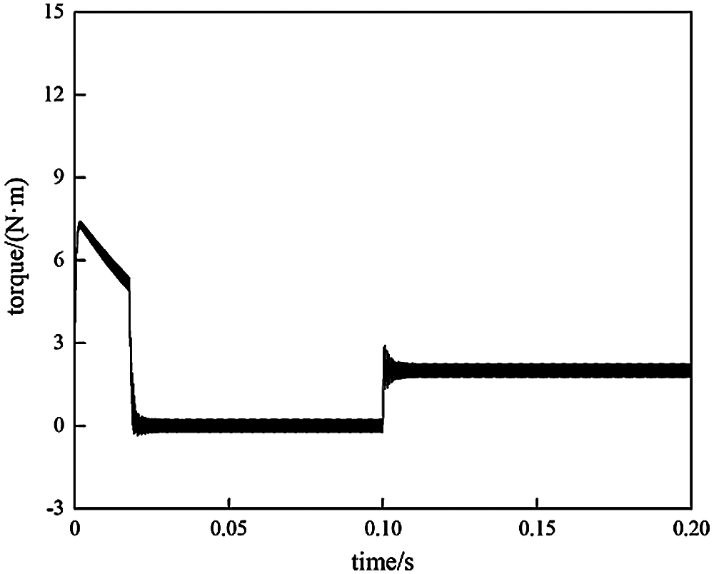
Figure 6: Simulation results of torque controlled by MFSMC
Fig. 4 gives the dynamic comparison diagram of estimated speed by SMO and the actual speed in the MFSMC. It shows that the observed speed by SMO tracks the actual speed, and the error is small.
Fig. 5 shows the dynamic comparison diagram of speed controlled by the MFSMC and the SMC when the torque changes. It can be seen that the speed response by MFSMC is faster than SMC. When the torque changes at 0.1 s, the speed fluctuation controlled by SMC was larger than MFSMC. The speed controlled by SMC tracked the reference speed slower than that controlled by MFSMC. So, the robustness of MFSMC is better than that of SMC.
Figs. 6 and 7 demonstrate the dynamic diagrams of motor torque controlled by MFSMC and MFC. It is also shown that the torque response of motor controlled by MFSMC is faster than that controlled by SMC.
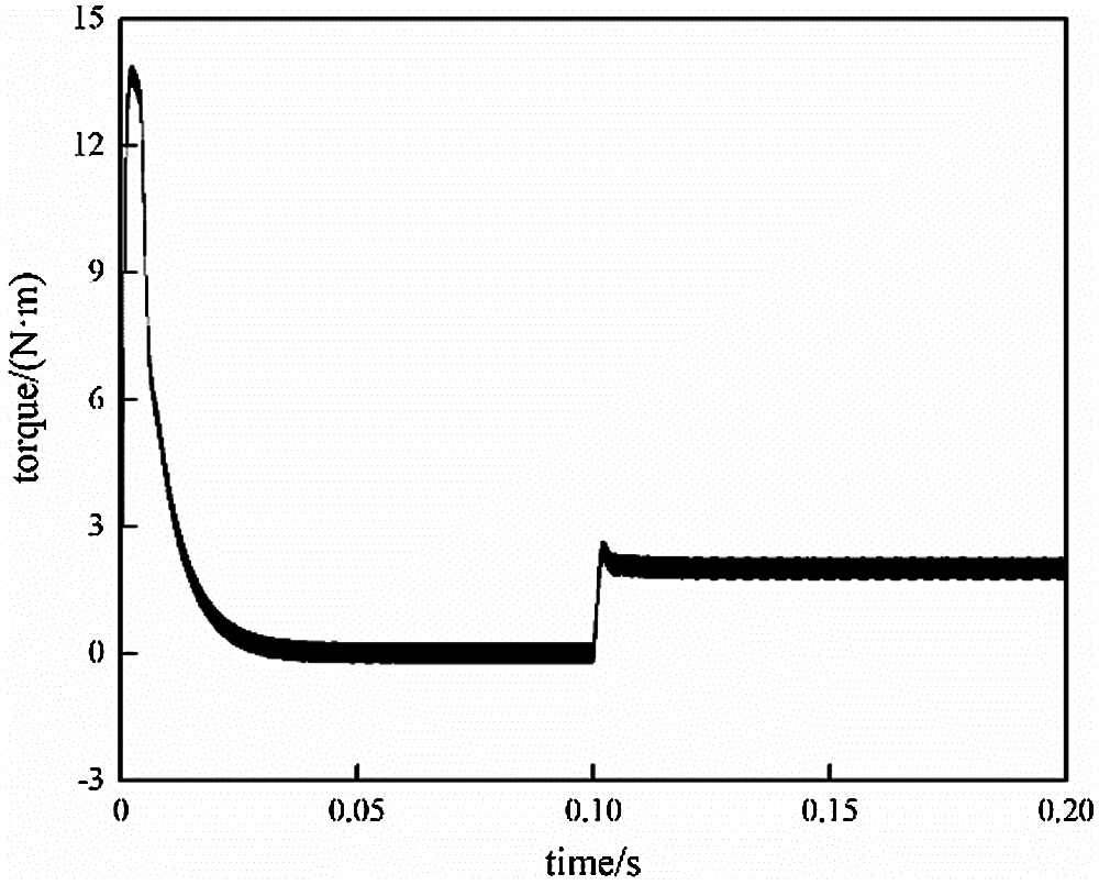
Figure 7: Simulation results of torque controlled by SMC
The hardware-in-the-loop simulation (HILS) experiments are carried out on an RT-Lab platform [7]. The HILS platform consists of a host computer, a DSP controller TMS320F2812, and an OP5600 simulator (Fig. 8a). Fig. 8b shows the RT-Lab HILS configuration diagram for the PMSM control systems. The experimental results are shown in Figs. 9–12.
Fig. 9 demonstrates the comparison diagram of the actual and reference speed controlled by the MFSMC method when the speed changes. Fig. 10 demonstrates the comparison diagram of the actual and reference speed controlled by the SMC method when the speed changes. It shows that the response of speed controlled by the MFSMC method is faster than that by the SMC method.

Figure 8: RT-Lab HILS platform. (a) RT-LAB. (b) Configuration diagram
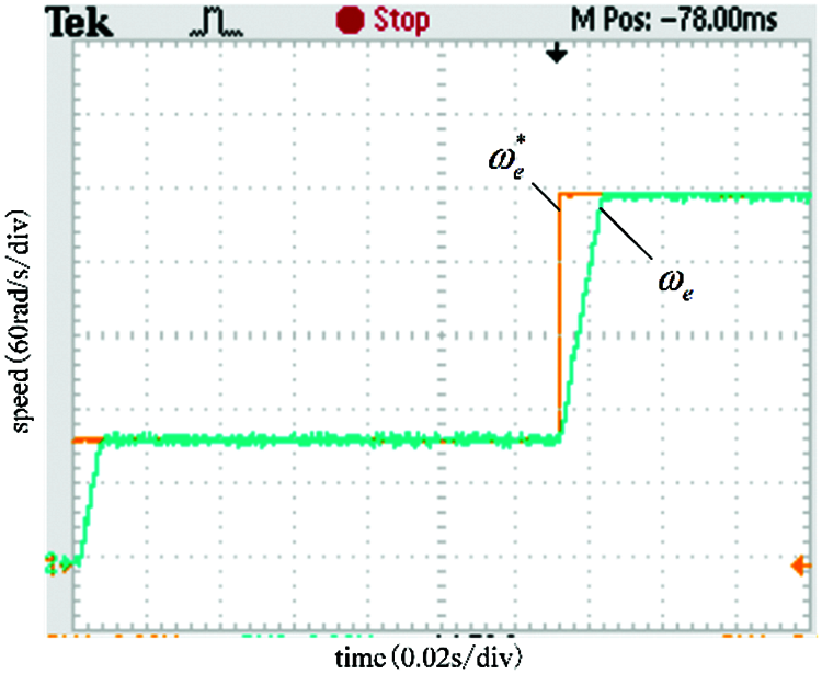
Figure 9: Experimental results of speed controlled by MFSMC

Figure 10: Experimental results of speed controlled by SMC
Fig. 11 presents the experimental results of speed and torque controlled by the MFSMC method when the torque changes. Fig. 12 presents the experimental results of speed and torque controlled by the SMC method when the torque changes. It shows that the response and robustness controlled by the MFSMC method are better than that controlled by the SMC method.
The above results (Figs. 4–11) for the SMC and MFSMC were summarized in Table 2.

Figure 11: Experimental results of speed and torque controlled by MFSMC

Figure 12: Experimental results of speed and torque controlled by SMC

This paper presented a novel MFSMC method to improve the speed response and robustness of the PMSM drive system. The ULM of the speed loop in PMSM is established based on the input and the output of the PMSM drive system. The MFSMC speed controller is designed based on ULM, and the SMO is designed to estimate the unknown part of ULM. The estimated unknown part is feedbacked to the controller to compensate for parameter perturbations and external disturbances. Compared with the SMC method, the results of simulation and experiment prove the presented method has excellent speed control performance and operates well. The MFSMC method has independence on the precise model of PMSM, and has faster response speed and strong robustness than the SMC method.
Funding Statement: This work was supported in part by the Hunan Provincial Natural Science Foundation of China under Grant Nos. 2020JJ6083, 2019JJ40072, 2021JJ50052 and 2020JJ6067, the Program of JSPS (Japan Society for the Promotion of Science) International Research Fellows under Grant No. 19F19703, the Scientific Research Fund of the Hunan Provincial Education Department under Grant No. 18A267, the Natural Science Foundation of China under Grant No. 61773159, in part by the Teaching Reform Research Project of Hunan Provincial Education Department of China (Hunan Education Notice [2019] No. 291) under Grant No. 543; and the Degree & Postgraduate Education Reform Project of Hunan Province under Grant No. 2019JGZD068.
Conflicts of Interest: The authors declare that they have no conflicts of interest to report regarding the present study.
1. Zhao, K. H., Chen, T. F., Zhang, C. F., He, J., Huang, G. (2015). Sensorless and torque control of IPMSM applying NFTSMO. Chinese Journal of Scientific Instrument, 6(2), 294–303. DOI 10.19650/j.cnki.cjsi.2015.02.007. [Google Scholar] [CrossRef]
2. Huang, G., Fukushima, E. F., She, J., Zhang, C., He, J. (2019). Estimation of sensor faults and unknown disturbance in current measurement circuits for PMSM drive system. Measurement, 137, 580–587. DOI 10.1016/j.measurement.2019.01.076. [Google Scholar] [CrossRef]
3. Zhao, K. H., Zhang, C. F., He, J., Li, X. F., Feng, J. H. et al. (2017). Accurate torque-sensorless control approach for interior permanent-magnet synchronous machine based on cascaded sliding mode observer. The Journal of Engineering, 2017(7), 376–384. DOI 10.1049/joe.2017.0160. [Google Scholar] [CrossRef]
4. Chang, X., Liu, L., Ding, W., Liang, D., Liu, C. et al. (2017). Novel nonsingular fast terminal sliding mode control for a PMSM chaotic system with extended state observer and tracking differentiator. Journal of Vibration and Control, 23(15), 2478–2493. DOI 10.1177/1077546315617633. [Google Scholar] [CrossRef]
5. Zhao, K. H., Li, P., Zhang, C. F., Li, X. F., He, J. et al. (2017). Sliding mode observer-based current sensor fault reconstruction and unknown load disturbance estimation for PMSM driven system. Sensors, 17(12), 1–26. DOI 10.3390/s17122833. [Google Scholar] [CrossRef]
6. Zhang, C. F., Wu, G. P., Fei, R., Feng, J. H., Jia, L. et al. (2018). Robust fault-tolerant predictive current control for permanent magnet synchronous motors considering demagnetization fault. IEEE Transactions on Industrial Electronics, 65(7), 5324–5334. DOI 10.1109/TIE.2017.2774758. [Google Scholar] [CrossRef]
7. Zhang, C., Wu, G., He, J., Zhao, K. (2017). Sliding observer-based demagnetisation fault-tolerant control in permanent magnet synchronous motors. The Journal of Engineering, 2017(6), 175–183. DOI 10.1049/joe.2016.0355. [Google Scholar] [CrossRef]
8. Zhao, K. H., Chen, T. F., Zhang, C. F., He, J., Huang, G. (2014). Online fault detection of permanent magnet demagnetization for IPMSMs by nonsingular fast terminal-sliding-mode observer. Sensors, 14(12), 23119–23136. DOI 10.3390/s141223119. [Google Scholar] [CrossRef]
9. Fan, Y., Zhou, X., Zhang, X., Zhang, L., Cheng, M. (2017). Sliding mode control of IPMSM system based on a new reaching Law and a hybrid speed controller. Transactions of China Electrotechnical Society, 32(5), 9–18. DOI 10.19595/j.cnki.1000-6753.tces.2017.05.002. [Google Scholar] [CrossRef]
10. Gao, Q. Z., Guan, H. X., Yu, Z. S., Zhou, S. (2017). Integral continuous sliding mode control strategy with adaptive compensator for permanent magnet synchronous motor. Electric Machines and Control, 21(2), 103–108. DOI 10.15938/j.emc.2017.02.013. [Google Scholar] [CrossRef]
11. Teng, Q., Xu, R., Han, X. (2020). Integral sliding mode-based model predictive current control with low computational amount for three-level neutral-point-clamped inverter-fed PMSM drives. IEEE Transactions on Energy Conversion, 35(4), 2249–2260. DOI 10.1109/tec.2020.3015984. [Google Scholar] [CrossRef]
12. Wang, Y., Li, H., Liu, R., Yang, L., Wang, X. (2020). Modulated model-free predictive control with minimum switching losses for PMSM drive system. IEEE Access, 8, 20942–20953. DOI 10.1109/ACCESS.2020.2968379. [Google Scholar] [CrossRef]
13. Zhang, Y., Jin, J., Huang, L. (2021). Model-free predictive current control of PMSM drives based on extended state observer using ultralocal model. IEEE Transactions on Industrial Electronics, 68(2), 993–1003. DOI 10.1109/tie.2020.2970660. [Google Scholar] [CrossRef]
14. Thabet, H., Ayadi, M., Rotella, F. (2016). Experimental comparison of new adaptive PI controllers based on the ultra-local model parameter identification. International Journal of Control Automation and Systems, 14(6), 1520–1527. DOI 10.1007/s12555-014-0550-1. [Google Scholar] [CrossRef]
15. Al Younes, Y., Drak, A., Noura, H., Rabhi, A., El Hajjaji, A. (2016). Robust model-free control applied to a quadrotor UAV. Journal of Intelligent & Robotic Systems, 84(1–4), 37–52. DOI 10.1007/s10846-016-0351-2. [Google Scholar] [CrossRef]
16. Fliess, M., Join, C. (2013). Model-free control. International Journal of Control, 86(12), 2228–2252. DOI 10.1080/00207179.2013.810345. [Google Scholar] [CrossRef]
17. Zhou, Y., Li, H., Liu, R., Mao, J. (2019). Continuous voltage vector model-free predictive current control of surface mounted permanent magnet synchronous motor. IEEE Transactions on Energy Conversion, 34(2), 899–908. DOI 10.1109/TEC.2018.2867218. [Google Scholar] [CrossRef]
18. Li, H., Li, X., Chen, Z., Mao, J., Huang, J. (2019). Model-free adaptive integral backstepping control for PMSM drive systems. Journal of Power Electronics, 19(5), 1193–1202. DOI 10.6113/jpe.2019.19.5.1193. [Google Scholar] [CrossRef]
19. Zhou, Y., Li, H., Zhang, H., Mao, J., Huang, J. (2019). Model free deadbeat predictive speed control of surface-mounted permanent magnet synchronous motor drive system. Journal of Electrical Engineering & Technology, 14(1), 265–274. DOI 10.1007/s42835-018-00022-8. [Google Scholar] [CrossRef]
20. Precup, R. E., Radac, M. B., Roman, R. C., Petriu, E. M. (2017). Model-free sliding mode control of nonlinear systems: Algorithms and experiments. Information Sciences, 381, 176–192. DOI 10.1016/j.ins.2016.11.026. [Google Scholar] [CrossRef]
21. Zhang, Y., Jiang, T., Jiao, J. (2020). Model-free predictive current control of a DFIG using an ultra-local model for grid synchronization and power regulation. IEEE Transactions on Energy Conversion, 35(4), 2269–2280. DOI 10.1109/TEC.2020.3004567. [Google Scholar] [CrossRef]
22. Zhou, Z., Zhang, B., Mao, D. (2018). Robust sliding mode control of PMSM based on rapid nonlinear tracking differentiator and disturbance observer. Sensors, 18(4), 1031. DOI 10.3390/s18041031. [Google Scholar] [CrossRef]
23. Spurgeon, S. K. (2008). Sliding mode observers: A survey. International Journal of Systems Science, 39(8), 751–764. DOI 10.1080/00207720701847638. [Google Scholar] [CrossRef]
 | This work is licensed under a Creative Commons Attribution 4.0 International License, which permits unrestricted use, distribution, and reproduction in any medium, provided the original work is properly cited. |