| Energy Engineering |
DOI: 10.32604/ee.2022.015594
ARTICLE
Comprehensive Energy-Saving Optimization Model of Asynchronous Motor for Voltage Regulation Based on Static Synchronous Compensator
College of Mechanical and Electrical Engineering, Henan Polytechnic, Zhengzhou, 450046, China
*Corresponding Author: Shuqiao Dan. Email: yycqrt@yeah.net
Received: 30 December 2020; Accepted: 06 May 2021
Abstract: There are several problems existing in the direct starting of asynchronous motor such as large starting current, reactive power absorption from network side and weak interference-resistance, etc. Aiming at this, a comprehensive energy-saving optimization model of asynchronous motor for voltage regulation based on static synchronous compensator (STATCOM) is put forward. By analyzing the working principle and operation performance of static synchronous compensator regulating voltage, a new energy-efficient optimization method for asynchronous motor is proposed based on the voltage regulator model to achieve soft start, continuous dynamic reactive power compensation and the terminal voltage stability control. The multi-objective optimal operation of asynchronous motor is realized by controlling the inverter to adjust the reactive current dynamically. The strategy reduces the influence of starting current and grid voltage by soft starting, and realizes the function of reactive power compensation and terminal voltage stabilization. The effectiveness and superiority of the proposed model is verified by the simulation analysis and the results of comparison with the motor started directly.
Keywords: Asynchronous motor; direct starting; static synchronous compensator (STATCOM); energy-saving optimization
Energy has a special status in the development of the national economy. At present, the contradiction between energy supply and demand in China is acute and energy utilization efficiency is low. Reasonable control of total energy consumption and improvement of energy utilization efficiency are important issues that must be resolved in economic development. At present, the electricity consumption of various types of motors in China accounts for about 60% of the country’s electricity consumption. Due to motor operating conditions, design, and enterprise industrial structure issues, domestic motors have considerable energy-saving space and great potential for energy saving. According to the characteristics of low power factor and low operation efficiency of high-power wound induction motor under light load and no-load operation, Wang et al. [1] explored the voltage regulation and energy saving method of high-power wound induction motor. Aiming at the problem that the traditional energy-saving control technology of three-phase asynchronous motor is difficult to ensure the system to achieve the minimum energy consumption, Bai [2] proposed the minimum energy consumption automatic optimization control method, and verified the reliability and effectiveness of the method through experiments. Huang [3] researched the mechanism of improving the startup performance to the deep grooves on double cage asynchronous motors. Wang [4] proposed an energy-saving control method of asynchronous motor, which combines the decoupling control based on neural network inverse system method with the energy-saving control strategy based on loss model. The simulation results show that the method has good dynamic energy-saving control effect and strong load tracking ability.
The static synchronous compensator (STATCOM) is based on the concept and compensation principle of instantaneous reactive power. It uses fully-controlled switching devices to form a self-commutated inverter, supplemented by small-capacity energy storage components to form a reactive power compensation device. It has the advantages of faster adjustment speed, wide operating range, continuous reactive power absorption, small harmonic current, low loss, greatly reduced installation area and capacity of reactor and capacitor compared with the existing static reactive power compensation device. Currently, the research hotspots of STATCOM mainly focus on the design of control methods and high-performance controllers, and the research of static synchronous reactive power compensators in distribution networks. In this paper, we proposed a comprehensive control model of the asynchronous motor based on the voltage regulation of the STATCOM to realize the energy-saving and optimized operation of the asynchronous motor by analyzing the working principle of the STATCOM and combining the converter control strategy.
Scholars have conducted in-depth research on energy-saving methods of asynchronous motors, and the results can be summarized into four methods. One is to optimize the structure of the motor. The magnetic flux in the air gap of the asynchronous motor will also produce odd harmonic components in addition to the fundamental wave, and the stator winding Cutting high-order harmonics generates high-order harmonic potential, which increases motor loss. It can effectively weaken or eliminate the harmonic potential and optimize the motor efficiency by optimizing the structure of the asynchronous motor winding [5–7]. The second is to save energy through reactive power compensation. The asynchronous motor, as an inductive load, needs to absorb reactive power from the power grid during operation. Therefore, installation of reactive power compensation equipment such as shunt capacitors can reduce the reactive power absorbed by the asynchronous motor from the power grid and transmitted by the line. As the reactive power flowing in the power grid is reduced, the power loss caused by the transmission of reactive power in the power grid can be reduced [8,9]. The third is variable frequency speed regulation. The excess torque increases the consumption of active power and causes a waste of electric energy when the asynchronous motor is running at no load or light load, and it can run in a constant voltage state and save energy by reducing the rotational speed of the asynchronous motor [10,11]. The fourth is voltage regulation: regulating the stator voltage of asynchronous motors. The electromagnetic torque is proportional to the square of the stator voltage at a certain speed when the structural parameters of the asynchronous motor are unchanged. The mechanical characteristics of the asynchronous motor can be adjusted by changing the voltage value applied to the stator, and the rotation speed of the asynchronous motor will be changed correspondingly under a certain load, so as to obtain a better energy-saving effect [12–14].
Other representative studies are as follows. Feng et al. [15] researched the operation performance of wound rotor asynchronous motors in voltage, and obtained the relationship between energy consumption of wound rotor asynchronous motor under optimal voltage by building the speed regulation model of step-down series resistance of wound rotor asynchronous motor. Liu et al. [16] explored the influence of air-gap length on magnetic field and performance of high-voltage induction motor. In order to realize the high efficiency operation of asynchronous motor under light load, Zhou et al. [17] applied the active disturbance rejection control strategy to the step-down energy-saving technology of asynchronous motor. In order to explore the comprehensive design method to improve the operation efficiency and power factor of small asynchronous motor, Zou et al. [18] used the finite element method to design and analyze, and obtained the individual optimization scheme from the motor structure and material respectively. Finally, the final optimization design scheme of the motor is determined after considering the factors of electromagnetic, structure, material and cost. Huang et al. [19] expounded The basic rules of the number of poles, power, current and torque of three-phase asynchronous motor by the ratio of starting current and starting torque to rated current and rated torque by the proportion of no-load running current of the same power and different pole number motor to rated current. By using the classical equivalent circuit, Chen et al. [20] set the step size within the parameter range of voltage fluctuation, and analyzed the variation of various losses and energy efficiency of asynchronous motor with parameters qualitatively and quantitatively. Liu [21] analyzed the characteristics of the windings and the influence of the number of phases on the magnetic potential and winding coefficient and established a two-dimensional transient electromagnetic field time stepping finite element model with field circuit coupling.
Existing research results are mainly optimized for a certain problem of asynchronous motors. There are relatively few studies on comprehensive optimization of asynchronous motor soft start, energy saving and consumption reduction, reactive power compensation and terminal voltage stability.
The STATCOM is a core device in the flexible AC power transmission system. It is an excellent result of the development of modern power electronics technology and is widely used in the field of reactive power compensation [13,14]. The principle of the STATCOM is shown in Fig. 1, where the inverter is composed of 6 power electronic switch-off devices.
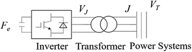
Figure 1: Principle diagram of STATCOM
The DC voltage is directly converted into AC voltage and the size, frequency and phase of the AC voltage are adjusted by adjusting the switchable power electronic devices in the inverter. The reactive power regulation principle of STATCOM is shown in Fig. 2.
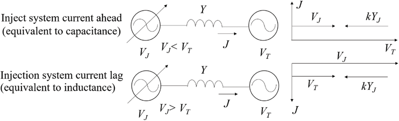
Figure 2: Regulation reactive power principle diagram of STATCOM device
According to the parameters in the figure, the output current of the STATCOM is
In Eq. (1), VJ is the voltage of the static synchronous compensation device, VT is the voltage on the power supply side, Y is the equivalent reactance of the system.
The complex power is
Since the device side is a reactive power source, the VJ and VT phases are almost the same, and the reactive power can be expressed as
When R < 0, the STATCOM is an inductance from the external characteristic; when R > 0, the STATCOM is a capacitor from the external characteristic.
The STATCOM is used as a reactive current source to dynamically adjust the reactive power of the system to achieve voltage stability control. According to the principle that the STATCOM can continuously and adjustably emit reactive current, a STATCOM is proposed. The method of adjusting the pressure is shown in Fig. 3.
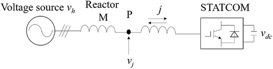
Figure 3: Voltage regulation method based on STATCOM
P is the adjustable voltage, vh is the voltage source voltage, M is the reactor, which acts as a voltage divider; j is the reactive current value sent by the static synchronous compensator; vdc is the voltage value of the DC side capacitor; vj is the adjust the voltage value in the figure.
The method achieves the purpose of continuous dynamic voltage regulation by controlling the magnitude and direction of the reactive current sent by the static synchronous compensator. If the reactive current from the static synchronous compensator passes through the reactor, the partial voltage on the reactor will change. If the reactor voltage and the power supply voltage are in the same direction, the voltage value at the adjustable voltage is the difference between the power supply voltage and the reactor voltage, and the regulation voltage decreases. If the reactor voltage and the voltage are reversed, the voltage value at the adjustable voltage is the sum of the voltage and the reactor voltage, and the regulation voltage rises.
If the power on the reactor is
j is the reactive current flowing through the reactor, x is the angular frequency of the power supply voltage in the formula.
4 Energy-Saving Control Method
Energy-saving control of asynchronous motors by means of voltage regulation is essentially to regulate and control the terminal voltage of asynchronous motors. This paper adopts the strategy of motor current open-loop control and motor terminal voltage closed-loop control in order to reduce the complexity of the control system. The principle of the control strategy is shown in Fig. 4.
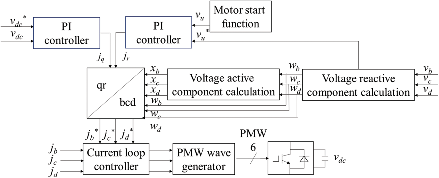
Figure 4: Voltage regulation energy-saving strategy of asynchronous motor
The current control loop is the control inner loop, and the voltage control loop is the control outer loop. jr is the reactive current output by the voltage controller of the asynchronous motor, and jq is the active current output by the DC side controller of the static synchronous compensator. jr and jq are transformed into j*b, j*c and j*d through 2/3, and then compared with the reference currents jb, jc and jd to output PWM waves, and finally drive the rectifier.
The controller is designed in the natural coordinate system. The three-phase instantaneous signal can be converted to the qr coordinate system for power decoupling processing in order to facilitate programming.
Suppose the terminal phase voltage values of the asynchronous motor are vb, vc, vd. The pressure amplitude can be expressed as
Let the unit component values of reactive power in the same direction as terminal voltage vb, vc, vd be wb, wc, wd, then
The unit component values of active power xb, xc, and xd orthogonal to wb, wc, and wd are
The outer control loop compares the given DC voltage with the feedback voltage value, and inputs the difference to the PI regulator, and the output value of the PI regulator is directly used as the given value of the q-axis current. The outer control loop compares the given AC voltage with the The feedback DC voltage value is compared, the difference is input to the PI regulator, and the output value of the PI regulator is directly used as the given value of the q-axis current.
Combining Eq. (6) can infer the three-phase reactive current value:
Combining Eq. (7) can infer the three-phase active current value:
Combining Eqs. (8) and (9) can infer the three-phase current reference quantity:
The system reactive power can be expressed as
The system active power can be expressed as
The mechanical power is expressed as
The energy consumed is expressed as
In order to simulate the soft-start process of the motor, a piecewise function is set as the given value of the terminal voltage, and the function is
When the asynchronous motor starts, the voltage regulator device of the static synchronous compensator applies the step-down start function shown in Eq. (15) to the motor terminal to realize the soft start of the asynchronous motor.
The asynchronous motor adopts squirrel cage self-excited type, the parameters of the motor and the parameters of the controller are shown in Table 1. The energy-saving simulation model of asynchronous motor based on the voltage regulation mode of static synchronous compensator is built in MATLAB environment. The simulation model is shown in Fig. 5.
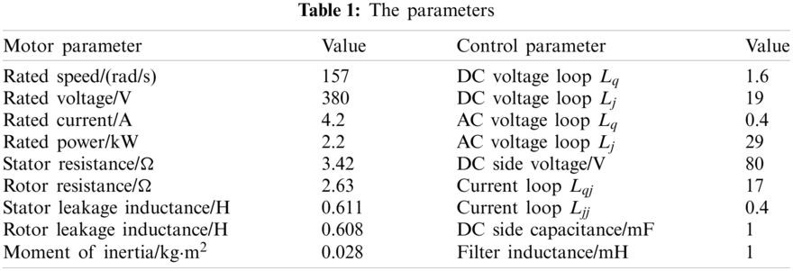
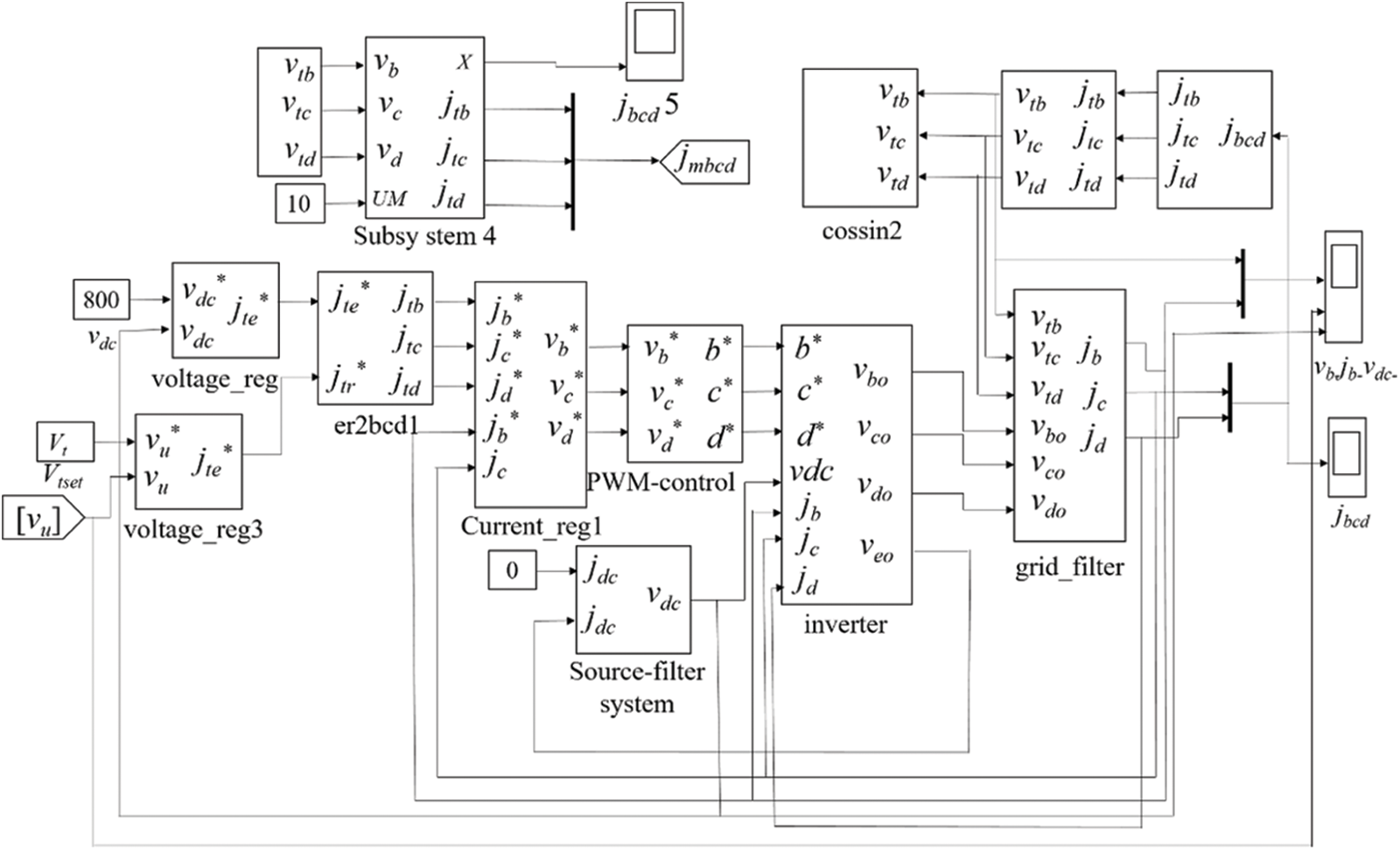
Figure 5: Simulation model
Comparing the soft start with the voltage regulation mode of the static synchronous compensator and the direct grid-connected start, as shown in Fig. 6, it can be seen that the active power of the asynchronous motor is about 1800 W during the soft start, which is 5000 W lower than the direct start of the motor. The mechanical power of the asynchronous motor is about 1500 W during soft start, which is 2000 W lower than the direct start of the motor. The reactive power during the soft start of the asynchronous motor is about 3000 var, which is 9000 var lower than the direct start of the motor. The power loss during the soft start of the asynchronous motor is about 1600 W, which is 4400 W lower than the direct start of the motor. The energy loss during the soft start of the asynchronous motor is about 800 J, which is 11.11% less energy than the direct start of the motor. The starting current is about 15 A when the motor is soft-started, which is about 50% lower than the direct start of the motor. Although there is an oscillation process of about 0.2 s during the soft-start process, the amplitude is about 4.5 times less than that of direct grid connection, which has less impact on the motor.
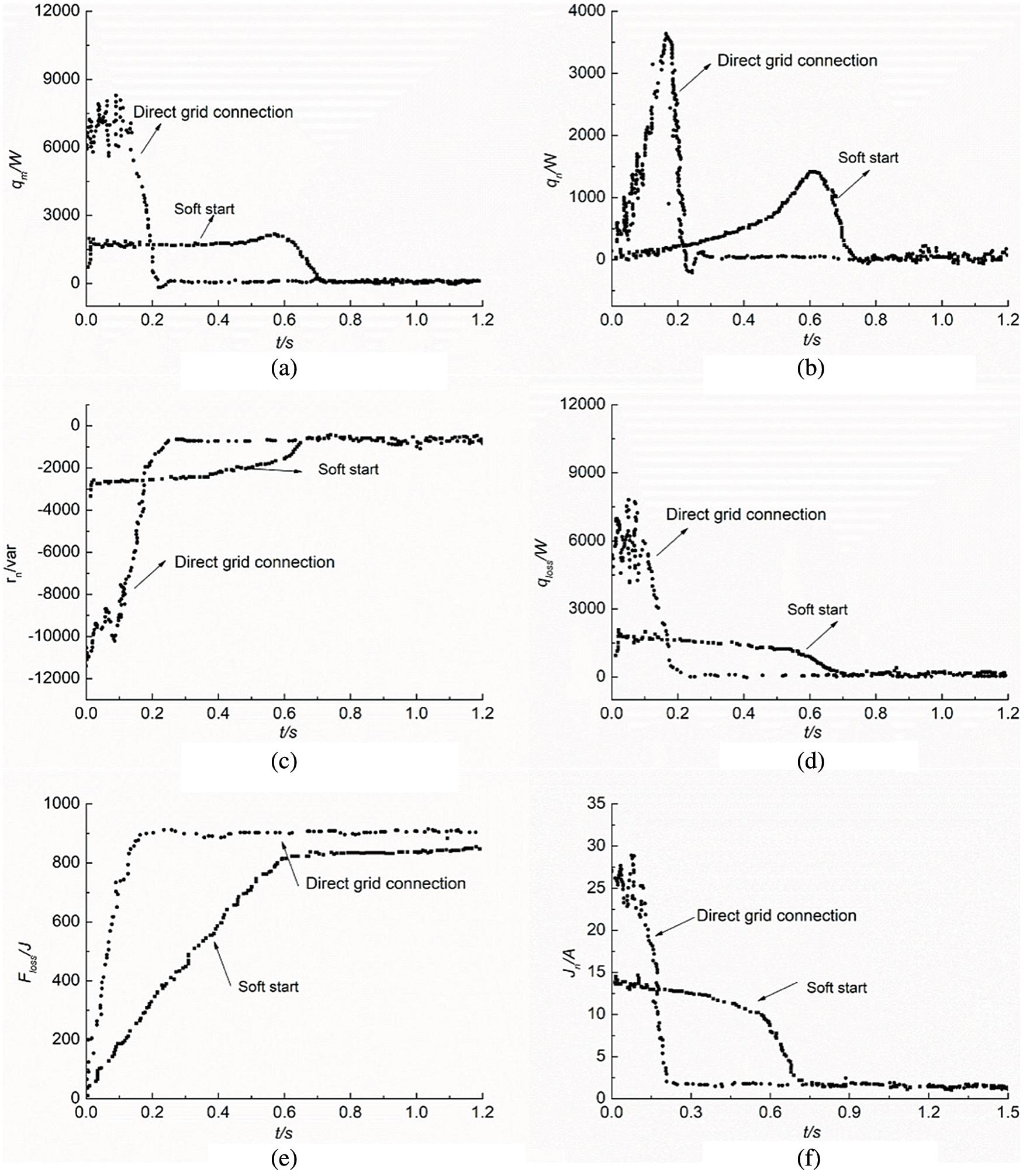
Figure 6: Waveform comparison. (a) Direct grid connection, (b) Mechanical power comparison, (c) Reactive power comparison, (d) Power loss comparison, (e) Energy loss comparison, (f) Starting current comparison
Adjust the voltage of the motor through STATCOM, and get the soft-start voltage waveform as shown in Fig. 7. The low-voltage start is performed within 0~0.52 s, the starting voltage is 160 V, and the given voltage within 0.52~1 s is a ramp signal, which makes the starting voltage go through a gradual process. The motor has started at 1.0 s, the terminal voltage is the rated value, and the terminal voltage amplitude fluctuates about 10 V. The harmonic content can be calculated to be less than 5%. It is approximately considered that the terminal voltage is perfect without harmonics.
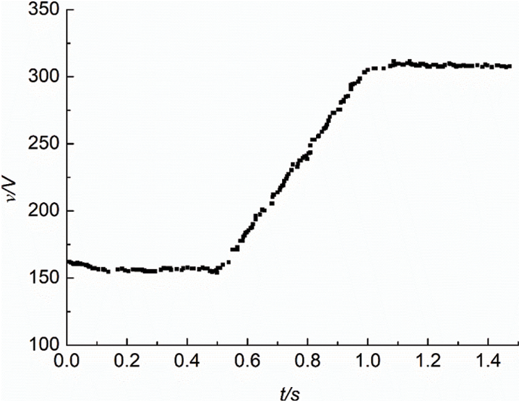
Figure 7: Terminal voltage waveform of motor
In order to simulate the difference of the anti-interference performance of the motor when the power supply voltage is unstable, it is verified through the simulation experiment of the motor voltage regulation. Assuming that the load torque is 9.5 N·m, the voltage on the power supply side drops from 312 V to 245 V at 2 s, a drop of 21.47%.
Fig. 8 is a comparison diagram of voltage mutation simulation. It can be seen from Fig. 8 that the terminal voltage of the asynchronous motor based on the static synchronous compensator voltage regulation method quickly returns to normal after being disturbed. The speed returns to the rated speed after 0.1 s, and the voltage drops with the voltage on the power supply side when the motor starts directly, and the speed drops by about 3.4%.
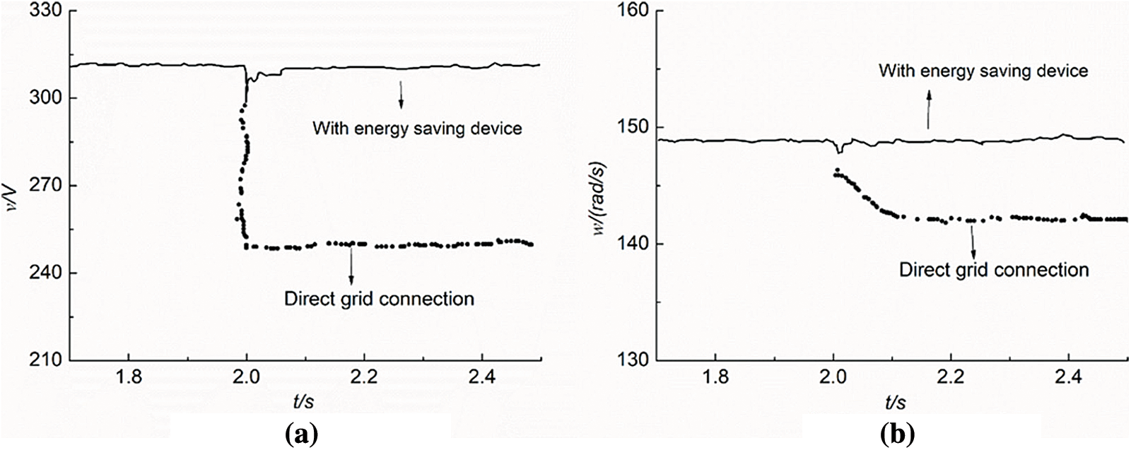
Figure 8: Simulation comparison of voltage mutation. (a) Terminal voltage comparsion, (b) Motor speed comparison
In summary, the simulation results show that the asynchronous motor soft-start model based on the voltage regulation mode of the static synchronous compensator can effectively reduce the starting current value and dynamically adjust the reactive current required by the motor in real time. The asynchronous motor is continuously regulated with reactive power to ensure the normal operation of the motor when the motor is disturbed by the external voltage.
The energy-saving control method of asynchronous motor based on the voltage regulation mode of the static synchronous compensator utilize the convenient control, sensitive adjustment response and wide operating range of the static synchronous compensator to realize the reduction of motor starting current, local dynamic reactive power compensation, real-time voltage stabilization and energy saving and consumption reduction. The use of static synchronous compensator device can not only stabilize the system, but also can cooperate with the reactor to realize the voltage adjustment, and has the advantages of large adjustment range, smooth adjustment, and less harmonic content. In this paper, the two-way dynamic adjustment of reactive current is realized by controlling the converter, and the multi-objective optimized operation of asynchronous motor is realized. This strategy can realize the soft start of the motor to reduce the starting current and the impact on the grid voltage, and can realize the functions of in-situ reactive power compensation and stabilize the terminal voltage. It can also reduce the harmonic content of the system. The energy saving effect is obvious, and the control performance is stable. The effectiveness of the method is verified through modeling simulation analysis and comparison with the asynchronous motor directly connected to the grid. This method can realize the energy-saving operation of the motor, strengthen the anti-interference performance of the asynchronous motor, and increase the service life of the asynchronous motor. In the future, the loss analysis and optimization design of capacitor elements based on STATCOM will be carried out on the basis of this research.
Funding Statement: The author received no specific funding for this study.
Conflicts of Interest: The author declares that they have no conflicts of interest to report regarding the present study.
1. Wang, B., Feng, R., Hou, L. (2017). Research on voltage regulation and energy saving control of winding asynchronous motor. Micromotors, 50(10), 53–57. DOI 10.15934/j.cnki.micromotors.2017.10.009. [Google Scholar] [CrossRef]
2. Bai, L. (2017). Minimum energy optimization control of three-phase asynchronous motor. Journal of Beihua University (Natural Science), 18(6), 820–825. DOI 10.11713/j.issn.1009-4822.2017.06.027. [Google Scholar] [CrossRef]
3. Huang, J. (2016). Research on the mechanism of improving the startup performance to the deep grooves on double cage asynchronous motors. Electrical Drive Automation, 38(2), 38–40. DOI 10.3969/j.issn.1005-7277.2016.02.009. [Google Scholar] [CrossRef]
4. Wang, K. (2016). A new energy saving method of asynchronous motor based on neural network inverse decoupling. Small & Special Electrical Machines, 44(4), 40–42. DOI 10.3969/j.issn.1004-7018.2016.04.012. [Google Scholar] [CrossRef]
5. Tousi, S. M. R., Aznavi, S. (2015). Performance optimization of a STATCOM based on cascaded multi-level converter topology using multi-objective genetic algorithm. 23rd Iranian Conference on Electrical Engineering, pp. 1688–1693. Tehran, IRAN. [Google Scholar]
6. Lazar, A., Chandel, A. K. (2020). Design of STATCOM for reactive power control using multilevel inverter. Journal of Physics: Conference Series, 1706(1), 12111. DOI 10.1088/1742-6596/1706/1/012111. [Google Scholar] [CrossRef]
7. Hu, G., Wu, F. (2011). Energy-saving technology of dynamic reactive power compensation based on STATCOM and fixed capacitor for HV induction motor. Electric Power Automation Equipment, 31(3), 75–78. DOI 10.3969/j.issn.1006-6047.2011.03.015. [Google Scholar] [CrossRef]
8. Mo, H., Zhong, Y. (2002). Optimal efficiency control of asynchronous motor based on copper loss equal to iron loss. Journal of Xi’an University of Technology, 18(2), 167–170. DOI 10.3969/j.issn.1006-4710.2002.02.014. [Google Scholar] [CrossRef]
9. Bian, X. Y., Geng, Y., Yuan, F. Q., Lo, K., Fu, Y. (2016). Identification and improvement of probabilistic voltage instability modes of power system with wind power integration. Electric Power Systems Research, 140, 162–172. DOI 10.1016/j.epsr.2016.06.026. [Google Scholar] [CrossRef]
10. Cui, N., Zhang, C., Du, C. (2004). Advances in efficiency optimization control of inverter-fed induction motor drives. Transactions of China Electrotechnical Society, 19(5), 36–42. DOI 10.3321/j.issn:1000-6753.2004.05.008. [Google Scholar] [CrossRef]
11. Matos, K., Londero, R., Affonso, C., Vieira, J. (2019). Secondary voltage control applied to DFIG-based wind park and its effect on long-term voltage stability. Electric Power Systems Research, 175, 105878. DOI 10.1016/j.epsr.2019.105878. [Google Scholar] [CrossRef]
12. Cui, X., Luo, Y., Yang, Y. (2008). Energy saving theory and approach for asynchronous motor under the periodically variable running condition. Proceedings of the CSEE, 28(18), 90–97. DOI 10.3321/j.issn:0258-8013.2008.18.016. [Google Scholar] [CrossRef]
13. Chen, Y., Wen, M., Wang, Z., Yin, X., Peng, J. et al. (2020). An improved numerical distance relay based on CCVT transient characteristic matching. International Journal of Electrical Power and Energy Systems, 122(1), 106146. DOI 10.1016/j.ijepes.2020.106146. [Google Scholar] [CrossRef]
14. Mitra, S., Srivastava, P., Lamba, J. (2018). Probabilistic assessment of projected climatological drought characteristics over the Southeast USA. Climatic Change, 147(3–4), 601–605. DOI 10.1007/s10584-018-2161-y. [Google Scholar] [CrossRef]
15. Feng, R., Wang, B., Hou, L. (2016). Research on the operation performance of wound rotor asynchronous motors in voltage regulation and energy saving. Journal of Hunan University of Technology, 30(3), 30–36. DOI 10.3969/j.issn.1673-9833.2016.03.006. [Google Scholar] [CrossRef]
16. Liu, Y., Sun, Q., Chen, H., Du, Z. (2018). Influence of air-gap length on magnetic field and performance of high-voltage induction motor. Explosion-Proof Electric Machine, 53(3), 16–20,23. DOI 10.3969/J.ISSN.1008-7281.2018.03.05. [Google Scholar] [CrossRef]
17. Zhou, X., Cui, H., Ma, Y., Gao, Z. (2018). Technology of voltage reduction and energy-saving for asynchronous motor based on LADRC. Proceedings of the CSU-EPSA, 30(2), 43–48. DOI 10.3969/j.issn.1003-8930.2018.02.008. [Google Scholar] [CrossRef]
18. Zou, Y., Li, Q., Huamg, H., Fan, H. (2018). Energy efficiency analysis of small premium industrial synchronous motors. Journal of Shanghai Dianji University, 21(6), 41–47. DOI 10.3969/j.issn.2095-0020.2018.06.008. [Google Scholar] [CrossRef]
19. Huang, L., Chen, J. (2019). Analysis on operation performance parameters of squirrel-cage three-phase induction motor. Explosion-Proof Electric Machine, 54(6), 23–25. DOI 10.3969/J.ISSN.1008-7281.2019.06.08. [Google Scholar] [CrossRef]
20. Chen, Z., Liu, Y., Chen, J., Wu, F. (2020). Effect of voltage fluctuation and flicker on energy efficiency of asynchronous motor. Small & Special Electrical Machines, 48(4), 32–38. DOI 10.3969/j.issn.1004-7018.2020.04.008. [Google Scholar] [CrossRef]
21. Liu, Y. (2020). Magnetic field and performance analysis of polyphase large capacity asynchronous motor. Electric Explosion Protection, 2, 1–6+10. DOI 10.14023/j.cnki.dqfb.2020.02.001. [Google Scholar] [CrossRef]
 | This work is licensed under a Creative Commons Attribution 4.0 International License, which permits unrestricted use, distribution, and reproduction in any medium, provided the original work is properly cited. |