| Energy Engineering |
DOI: 10.32604/ee.2022.019627
ARTICLE
An Improved Immune Clone Selection Algorithm for Parameters Optimization of Marine Electric Power System Stabilizer
Department of Electrical Engineering, Shanghai Maritime University, Shanghai, 201306, China
*Corresponding Author: Zong Bi. Email: 18295997624@163.com
Received: 03 October 2021; Accepted: 22 December 2021
Abstract: In the marine electric power system, the marine generators will be disturbed by the large change of loads or the fault of the power system. The marine generators usually installed power system stabilizers to damp power system oscillations through the excitation control. This paper proposes a novel method to obtain optimal parameter values for Power System Stabilizer (PSS) to suppress low-frequency oscillations in the marine electric power system. In this paper, a newly developed immune clone selection algorithm was improved from the three aspects of the adaptive incentive degree, vaccination, and adaptive mutation strategies. Firstly, the typical PSS implementation type of leader-lag structure was adopted and the objective function was set in the optimization process. The performance of PSS tuned by improved immune clone selection algorithm was compared with PSS tuned by basic immune clone selection algorithm (ICSA) under various operating conditions and disturbances. Then, an improved immune clone selection algorithm (IICSA) optimization technique was implemented on two test systems for test purposes. Based on the simulations, it is found that an improved immune clone selection algorithm demonstrates superiority over the basic immune clone selection algorithm in getting a smaller number of iterations and fast convergence rates to achieve the optimal parameters of the power system stabilizers. Moreover, the proposed approach improves the stability and dynamic performance under various loads conditions and disturbances of the marine electric power system.
Keywords: Marine electric power system; excitation system; immune clone selection algorithm; low frequency oscillations; power system stability
Nomenclature
| Rotor angle deviation | |
| Rotor speed deviation | |
| Quadratic axis transient potential deviation | |
| Excitation voltage deviation | |
| Rotor angle | |
| Rotor speed | |
| Quadratic axis transient potential | |
| Excitation voltage | |
| Inertia coefficient | |
| Damping coefficient | |
| Synchronous speed | |
| Direct axis open-circuit time constant | |
| Mechanical torque | |
| Gain of AVR | |
| Time constant of AVR | |
| Output signal of the PSS | |
| Constants of the linearized model of synchronous machine | |
| Gain of PSS | |
| Time constant of washout filter | |
| PSS's lead–lag time constants | |
| Speed of the generator | |
| Reference speed | |
| Terminal voltage | |
| Reference voltage | |
| Stabilizers’ output | |
| PSS's output limits | |
| Integral of time-absolute error | |
| Population size | |
| Encoding dimension of the antibody | |
| Similarity threshold | |
| Affinity weight coefficient | |
| Current iteration number | |
| Maximum iteration number | |
| Total amount of antibody after cloning | |
| Number of antibodies to be cloned | |
| Antibody gene before mutation | |
| Antibody gene after mutation | |
| Direct axis reactance of the generator | |
| Direct axis transient reactance of the generator | |
| Direct axis sub transient reactance of the generator | |
| Quadratic axis reactance of the generator | |
| Quadratic sub axis reactance of the generator | |
| Direct axis leakage reactance of stator winding | |
| Direct axis open-circuit time constant | |
| Excitation winding time constant of generator suddenly short circuit | |
| Damping winding time constant of generator suddenly short circuit |
Due to the bad marine environment and the change of loads, the operation stability of the marine electric power system is affected. The marine generator is prone to produce low-frequency oscillations, which will affect the stability and performance of the marine electric power system.
Power system stabilizers are commonly used to improve the stability of marine electric power systems. By introducing a power system stabilizer to increase damping in the excitation control system of the marine generator, the dilemma of insufficient damping of the marine electric power system can be solved and the low-frequency oscillations can be suppressed [1]. The stable operation of diesel generators in marine electric power systems greatly affects the stable operation. This paper studies the excitation control system of marine generators that are set in marine electric power system and tunes the power system stabilizer to ensure the continuous power supply and navigation safety of the marine electric power system [2].
In reference [3], the root locus method is employed to tune the traditional power system stabilizer. However, these methods also have some defects. For example, the calculation results fall into optimal results and the full-dimensional equation of state is difficult to obtain. Many intelligent optimization algorithms with high global optimization ability and great adaptability have been used in PSS design. In reference [4], the genetic algorithm is presented for tuning power system stabilizers, it shows good performance for large and small disturbances in the single-machine infinite system, with good convergence and less calculation time. But it always tends to local optimal results. In [5], a bat algorithm is employed to achieve the optimal PSS parameters in the power system, but the results of the algorithm tend to be local optimal results. Reference [6] presents the gray wolf optimization algorithm for the coordinating of the power system stabilizer, but the ability to find the global optimal solution is not good. In reference [7], the annealing algorithm is used for the optimization of power system stabilizers parameters. The algorithm does not depend on the initial value and has a high searching ability, but it is easily affected by the number of iterations, temperature, and other parameters. In reference [8], a modified Nyquist diagram is used to design power system stabilizers. Reference [9] proposes a double-objective optimization function to adjust the PSS for different input signals. In reference [10], the authors propose an NSGA-II genetic algorithm to tune the parameters of the power system stabilizers controllers for a determined point of operation with a renewable energy source to increase and guarantee the damping of the system. In reference [11], a firefly algorithm is presented for tuning the power system stabilizers. In reference [12], the Hyper-Spherical Search (HSS) algorithm is presented for tuning the power system stabilizers. In reference [13], a backtracking search algorithm (BSA) is employed to achieve the optimal values of the power system stabilizers in a multi-machine power system. Reference [14] proposes a novel bat algorithm (NBA) to optimize the parameters of the power system stabilizers to minimize the low-frequency electromechanics oscillations. In reference [15], the authors propose a model reference adaptive system, and the system is better than the conventional power system stabilizer. Reference [16] presents the firefly algorithm to improve the small-signal stability under renewable-energy-resource integration. In reference [17], a parallel genetic algorithm is proposed to tune the power system stabilizers to achieve both dynamic responses encompassing several critical operating conditions to reduce high computational efforts. In reference [18], the power system stabilizer parameters are optimized based on both the amplitude-frequency and the phase-frequency properties. In reference [19], the authors propose a Particle Swarm Optimization (PSO) to tune the parameters for power system stabilizers for relatively small systems. In reference [20], the PSS4B has been used as a static VAR compensator to damp oscillations in multi-machine power systems. Reference [21] presents a comprehensive learning bat algorithm (CLBAT) to adjust the parameters of power system stabilizers. In reference [22] a newly developed genetic algorithm is presented for tuning the PSSs parameters under various loading conditions to dampen the low-frequency oscillations. In reference [23], a customized differential evolution algorithm is employed to design probabilistically-robust wide-area power system stabilizers (WPSSs) for damping the low-frequency oscillations in power systems with wind power. In reference [24], an improved active set algorithm is presented to tune the double input power system stabilizers based on phase-frequency characteristics. In reference [25], the switching power system stabilizer (SPSS) is employed to improve the stability of multi-machine power systems.
The main contribution of this paper is as follows:
1. Use of an improved immune clone selection algorithm to coordinate the power system stabilizers.
2. Development of an improved immune clone selection algorithm from three aspects: adaptive incentive degree, vaccination, and adaptive mutation strategies.
3. Comparison of the improved immune clone selection algorithm with other optimization techniques in tuning the parameters of power system stabilizers.
4. It analyzes the efficiency of the PSS controllers when the marine electric power system is under various operating conditions and disturbances.
The organization of the research is as follows: The modeling of the marine diesel generator and the structure of the PSS are introduced in Section 2. The objective function is described in Section 3. The improved immune clone selection algorithm for tuning PSS parameters is presented in Section 4. The simulation studies and results are discussed in Section 5. The conclusions and future studies are presented in Section 6.
2.1 Marine Diesel Generator Model
For diesel generator, the mathematical model is shown in Eq. (1):
where, X is the vector of the state variables, A is the state space matrix, B is vector the input matrix, U is the PSS output signal [26]. The Heffron-Philips model is commonly used in damping control design. Herron-Philips model of synchronous generator is shown in Fig. 1.

Figure 1: The Herron-Philips model of synchronous generator [27]
In Eq. (2), the diesel generator in a marine electric power system is studied by using a third-order dynamic equation [26].
where,
Herron-Philips's linearization model [28] of synchronous generator is shown in Eq. (3):
where,
2.2 Power System Stabilizer Modeling
The marine diesel generator controller is shown in Fig. 2. In the excitation control system of a marine diesel generator, the terminal voltage of the generator is regulated by the automatic voltage regulator. The role of PSS is to generate an appropriate torque on the generator rotor, which is used to improve the dynamic stability of marine diesel generators [29].

Figure 2: Block diagram of AVR and PSS transfer function are the gain and time constants of AVR
The first-order transfer function of AVR [30] is shown in Eq. (4):
where,
The PSS controller adopts two lead-lag transfer functions [31] is shown in Eq. (5):
where, K is the gain of stabilizer,
In order to make the output deviation of the marine electric power system smaller and ensure good dynamic performance and good stability when the low-frequency oscillations occur. The error performance index
In Eq. (6),
4 The Improved Immune Clone Selection Algorithm
4.1 Basic Immune Clone Selection Algorithm
The flow of the basic immune clone selection algorithm is as follows:
Step 1: Generate the initial antibody population.
Step 2: The concentration of antibodies is obtained in Eq. (7):
where,
In Eq. (8), the affinity index of antibodies is obtained:
where,
Antibody concentration index is shown in Eq. (9):
where, N is the antibody scale; In Eq. (10),
where,
Step 3: Judgment of the program termination. If the algorithm obtains the optimal value of power system stabilizers. Otherwise, the algorithm optimization is continued.
Step 4: Evaluation of antibody excitation degree. Antibody excitation degree is a comprehensive evaluation index based on antibody concentration and affinity.
Step 5: Promotion and inhibition of antibodies. Clone proliferation, clone mutation, clone suppression.
Step 6: Population refresh. Arrange the antibodies in order of their excitation. A part of the antibodies with low excitation degree in the population was removed. The new antibodies were randomly generated to supplement and update the original antibody population. To form a new population, proceed to Step 2.
4.2.1 Adaptive Excitation Degree
If only the evaluation index based on antibody affinity is considered, it is difficult to ensure that the best solution can be selected. Comprehensive evaluation indexes based on antibody concentration and affinity were considered to avoid premature maturation and the local optimal solution. In Eq. (11), the adaptive excitation degree based on the number of iterations was adopted to ensure the selection of excellent antibodies for cloning and accelerate the convergence rate of the algorithm. To ensure that the best antibodies in the population are selected [34].
where,
where, T is the current iteration number,
In Eq. (13), the clone scale of antibody can be expressed as:
where,
The lack of antibody gene crossover in the basic ICSA results in insufficient diversity of antibodies production. The introduction of a vaccination strategy based on the basic ICSA not only preserves the genes of the superior parent antibody, but also increases the probability of producing a superior antibody. To ensure that the best antibody in the population is selected. Antibody populations with high excitation were used as candidate vaccines. Vaccines were selected according to the roulette method [35]. The steps for selecting vaccines are as follows:
Step 1: The sum of all antibody excitation degrees in the population can be calculated by Eq. (14):
Step 2: The ratio of each antibody's incentive degree to the sum of the population's incentive degree can be calculated by Eq. (15):
Step 3: The selection probability of antibody corresponds to the interval on the roulette wheel.
Step 4: Use roulette to select individuals randomly.
The binary loci method [35] was used to inoculate candidate antibodies.
In order to ensure the randomness and diversity of antibodies, adaptive variation in Eq. (16) and gaussian variation based on antibody affinity in Eq. (17) are adopted to basic ICSA. To ensure that the algorithm picks the best antibody in the population.
where, Y is the antibody gene before mutation.
4.3 Optimization Process of PSS Based on Improved Immune Clone Selection Algorithm
The specific flow of the IICSA algorithm is as follows:
Step 1: Generation of the initial antibody population. The initial population was composed of the antibody memory bank and the general population. The size of the antibody population was 30 and the number of antibody memory banks accounted for 40% of the population.
Step 2: Calculate the adaptive excitation degree of the antibody. Put the first M antibodies with the highest excitation into the antibody memory bank. The antibody memory bank is updated.
Step 3: Antibody cloning. The antibody was cloned from the antibody memory bank. The clonal scale of each antibody was determined according to the excitation degree of the antibody in the antibody memory bank.
Step 4: Vaccination. Vaccines come from an antibody memory bank. The probability of each antibody being selected is determined according to the excitation degree of the antibody. Roulette algorithm was used to select vaccines. Vaccination was conducted by multi-point cross vaccination.
Step 5: Clone variation. For inoculated antibodies, adaptive variation and gaussian variation based on antibody affinity were used.
Step 6: Clone suppression. The excitation degree of each antibody was calculated after the mutation. The first M antibodies with the highest excitation degree were re-selected and put into the antibody memory bank to realize the update of the antibody memory bank. After the update of antibody memory, all the remaining antibodies were eliminated.
Step 7: Population regeneration. At the end of each iteration of the algorithm, the population needs to be updated. The updated population still consists of the antibody memory bank and the general population. The maximum number of iterations of the algorithm is 100.
Step 8: Judgment of termination conditions. When the termination conditions are satisfied, output the optimal parameters of the marine electric power system stabilizer. Otherwise, go to Step 2.
In Fig. 3, it is a flow chart of PSS parameters optimization strategy. The power system stabilizer of marine electric power system simulation model optimized by IICSA. The optimal PSS parameters are obtained when the iteration condition is satisfied.

Figure 3: Flow chart of PSS parameter optimization strategy
5 Simulation Results and Discussion
5.1 Convergence Characteristics of Different Algorithms in Finding the Optimal Design of PSS
5.1.1 Convergence Characteristics of ICSA and IICSA in Finding the Optimal Design of PSS
The objective function evolution with ICSA based PSS and IICSA based PSS as a function of generation is shown in Fig. 4. In Fig. 4a, we find the final value of the objective function for ICSA is 0.1528 from the 56 iterations. In Fig. 4b, we notice that the final value of the objective function for IICSA is 0.1496 from the 21 iterations. It can be observed from Fig. 4 that IICSA can not only find optimal value in search space, but also has a relatively fast convergence rate to ensure the best antibody in the population.

Figure 4: Convergence characteristics of different algorithms in finding the optimal design of PSS. (a) ICSA, (b) IICSA
5.1.2 Convergence Characteristics of SSA, GOA, and IICSA in Finding the Optimal Design of PSS
In order to illustrate the efficiency of the improved immune clonal selection algorithm, the salp swarm algorithm (SSA) [36] and the grasshopper optimization algorithm (GOA) [37] are compared with the IICSA to show their effect on convergence rate. These algorithms were run with the same population size and a maximum number of iterations. According to the analysis of the convergence curve in Fig. 5, we notice that the IICSA attains at the end of optimization a value of 0.1495 lower than the 0.1496 that SSA delivers. The GOA reaches the optimal value of 0.1496 in 61 iterations while the IICSA reaches the optimal value of 0.1496 in 21 iterations. It was found that IICSA gives the fastest convergence and minimum fitness value in these algorithms. The result also shows that the IICSA can obtain the optimal tuning parameters for power system stabilizers of marine electric power system.
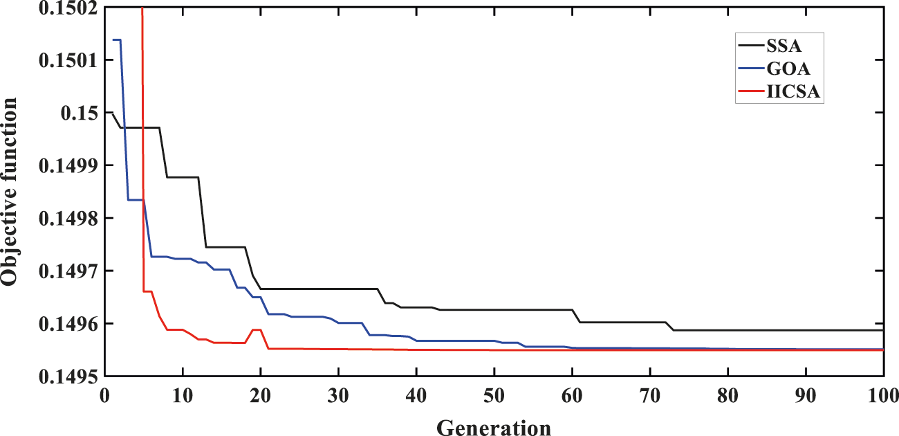
Figure 5: Convergence characteristics obtained by different algorithms
5.2 Controller Performance Evaluation
The parameters of these controllers are optimized by improved immune clonal selection algorithm. The objective function is in Eq. (6). In order to show the superiority of the PSS controller over the PI, PID, and FOPID [38] controllers, the +15% load changes on marine electric power system start at 2.5 s and end at 4.5 s. The optimized parameters of these controllers are shown in Table 1. In Fig. 6, when the marine electric power system adopts PI controller, the rotor speed deviation is 0.76%, and the system produces low-frequency oscillations. However, when the marine electric power system adopts PID controller, the rotor speed deviation is 0.67% and the settling time is 3.5 s. The results show that PID controller is better to reduce the maximum deviation in the marine electric power system than the PI controller. When the marine electric power system adopts FOPID controller, the rotor speed deviation is 0.60% and the settling time is 2 s. The results show that FOPID controller can reduce the response time and maximum deviation of the marine electric power system and improve the response rate. When the marine electric power system adopts PSS controller, the rotor speed deviation is 0.48% and the settling time is 1 s. The controller can greatly reduce its response time and maximum deviation, and significantly suppress the low-frequency oscillations of the marine electric power system. After comparison, it can be concluded that the relative control performance of PSS controller is the best in these controllers.

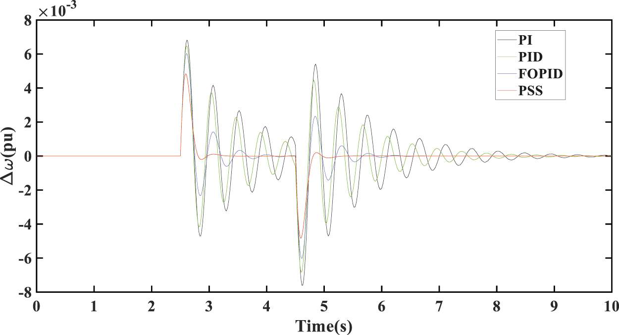
Figure 6: PSS controller compared with conventional PI, PID, and FOPID controllers
5.3 The Simulation Results of PSS Parameters Optimized by ICSA and IICSA
The proposed marine electric power system can be found in [39]. The marine generator is a single generator. The main switch bus is granted as an infinite bus and also as a reference.
The parameters of the marine generator in the simulation are set as follows [17]:
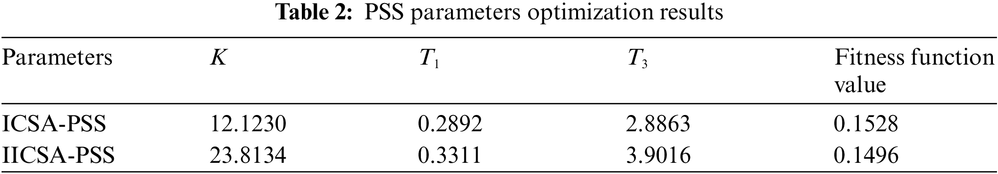
In the same case, PSS parameters optimization results of basic ICSA and IICSA algorithms are shown in Table 2.
In order to verify the excellent effect of the IICSA algorithm to optimize the stabilizer parameters of the marine electric power system. The marine electric power system is disturbed by 15% load changes, a 10% increase of excitation voltage reference value, and a sudden short circuit fault of the marine generator. The rotor speed deviation and generator terminal voltage deviation were observed under three conditions: no PSS (the marine electric power system is without PSS), PSS parameters optimized by ICSA, PSS parameters optimized by IICSA.
5.3.1 The Increase of 15% Load on Marine Generator
The +15% load changes on the marine electric power system start at 2.5 s and end at 4.5 s. It is a small type of disturbance for a marine electric power system. The generator rotor speed deviation and generator terminal voltage deviation are shown in Fig. 7 By observing Fig. 7, it can be found that when there is no power system stabilizer in marine electric power system, the generator rotor speed deviation reaches 0.52%. The speed deviation of the power system stabilizer optimized by ICSA is 0.45%, which is smaller than the diesel generator without the power system stabilizer. So, the power system stabilizers improved the capacity of the marine electric power system to suppress low-frequency oscillation.
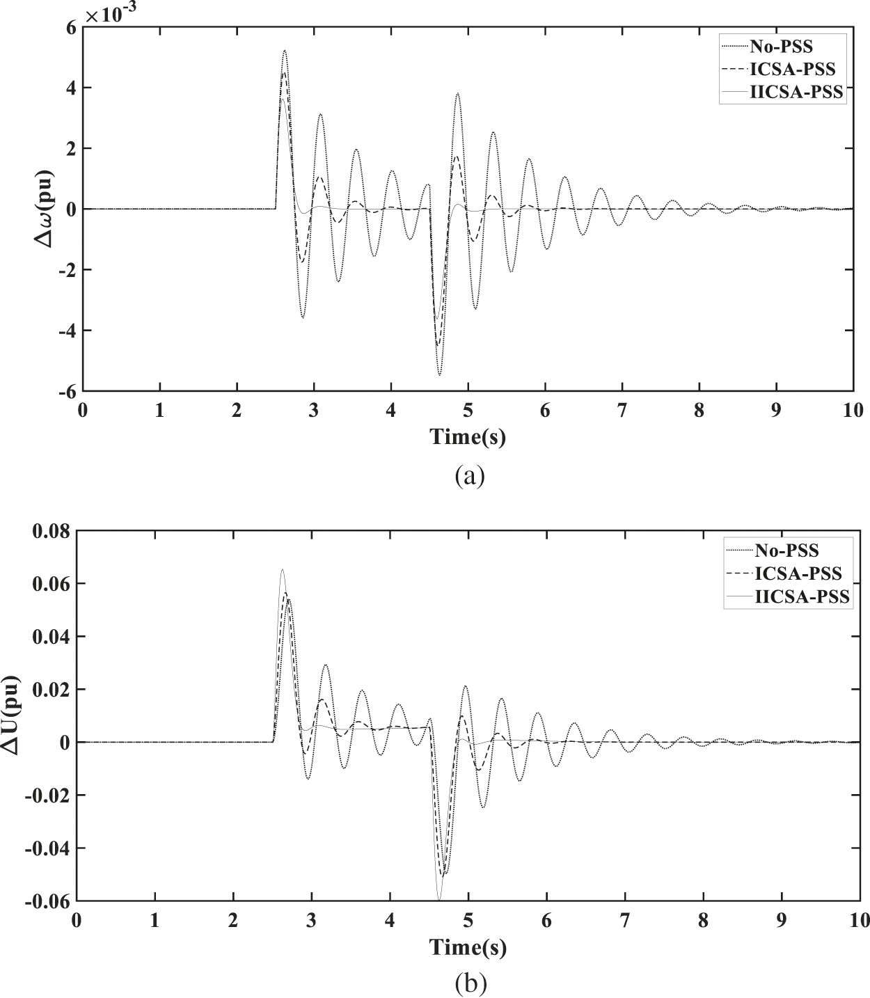
Figure 7: (a) Rotor speed deviation of the marine generator for +15% load changes. (b) Terminal voltage deviation of the marine generator for +15% load changes
After being disturbed, the time of the transition process is 2 s and the number of oscillations is 3 when the PSS is optimized by ICSA. However, the time of the transition process is 1 s and the number of oscillations is 1 when the PSS is optimized by IICSA. In terms of generator terminal voltage deviation, the voltage deviation is 6.18% when the power system stabilizer is optimized by IICSA, which is higher than the power system stabilizer is optimized by ICSA. The voltage deviation is 5.65% when the power system stabilizer is optimized by ICSA. But, the IICSA optimized power system stabilizer exhibits better damping than ICSA optimized power system stabilizer.
5.3.2 The Reference Value of the Marine Generator Excitation Voltage is Increased by 10%
Marine diesel generator excitation voltage reference value is increased by 10%. It starts at 2 s and ends at 2.2 s. By observing Fig. 8, it is found that the low-frequency oscillations in the marine electric power system is significantly reduced after the installation of the power system stabilizer. In terms of generator rotor speed deviation, when the marine generator adopts the power system stabilizer optimized by ICSA, the generator rotor speed deviation is 0.22%, while the generator rotor speed deviation is 0.18% by IICSA.
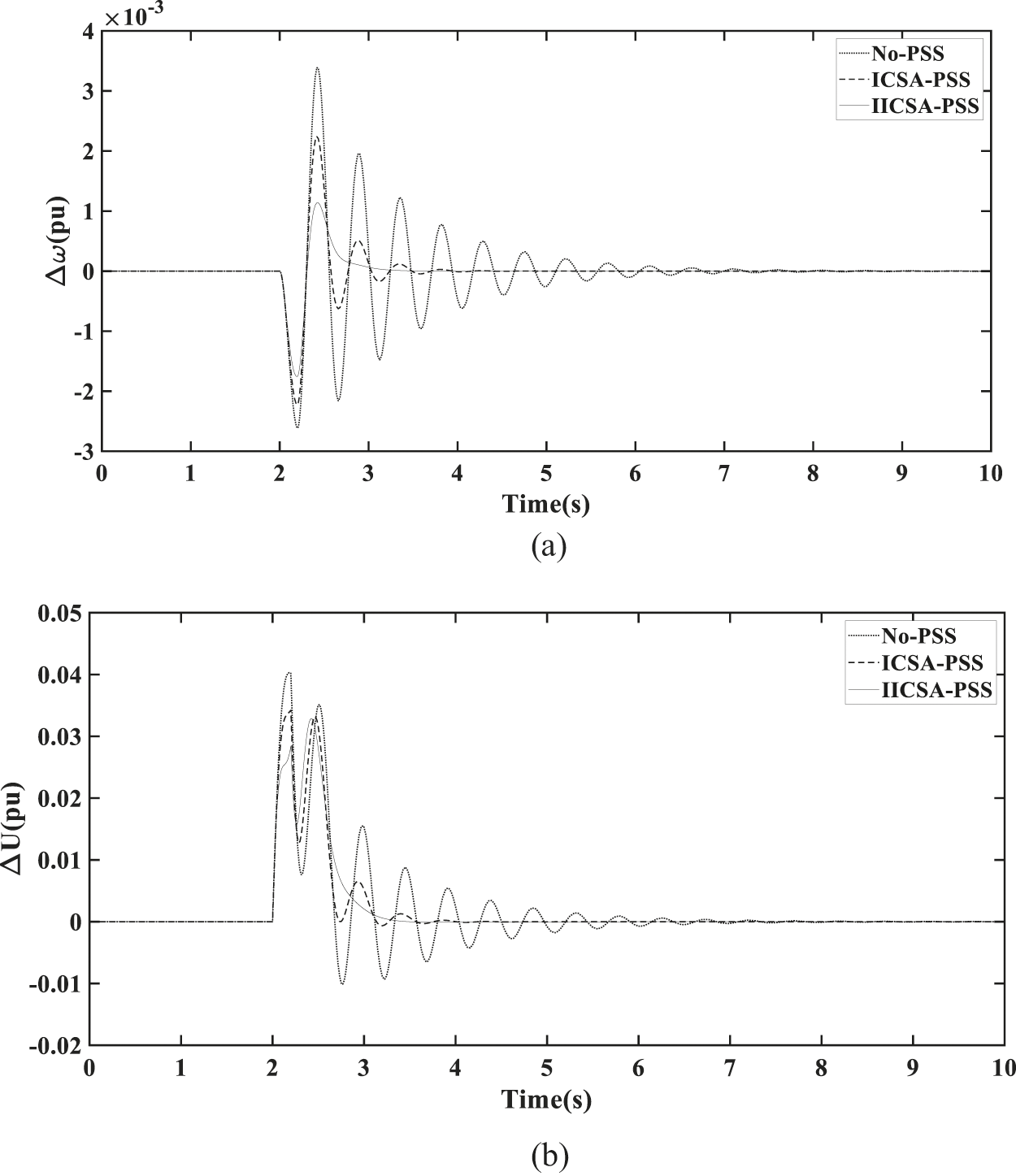
Figure 8: (a) Rotor speed deviation for +10% reference value of the excitation voltage. (b) Terminal voltage deviation for +10% reference value of the excitation voltage
After being disturbed, the time of the transition process is 2 s and the number of oscillations is 4 when the PSS is optimized by ICSA. However, the time of the transition process is 1 s and the number of oscillations is 1 when the PSS is optimized by IICSA. In terms of generator terminal voltage deviation, the terminal voltage deviation is 3.43% when the marine generator adopts a power system stabilizer optimized by ICSA. However, the generator terminal voltage deviation is 2.84% that optimized by IICSA. It is showing that the system having IICSA optimized PSS shows better performance than the system having ICSA optimized PSS.
5.3.3 Short Circuit Fault in the Marine Generator
A short circuit fault of marine diesel generator. The short circuit starts at 2 s and ends at 2.2 s. The rotor speed deviation of the marine generator for short circuit is shown in Fig. 9a, the terminal voltage deviation of the marine generator for the short circuit is shown in Fig. 9b. From the simulation results of the marine generator system response to short circuit. It is found that the low-frequency oscillation in marine electric power systems decreases significantly after the installation of a power system stabilizer than the system without a power system stabilizer. In terms of generator rotor speed deviation adjustment, the speed deviation is 1.8% when the marine diesel generator adopts the basic ICSA to optimize the power system stabilizer. However, the rotor speed deviation is 1.4% when the power system stabilizer is optimized by the IICSA.
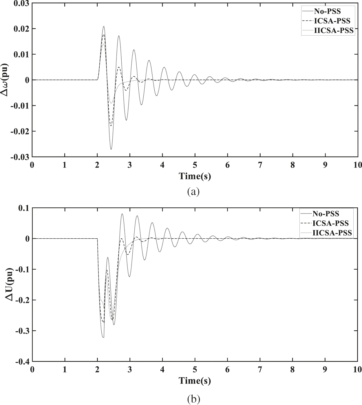
Figure 9: (a) Rotor speed deviation of the marine generator for short circuit. (b) Terminal voltage deviation of the marine generator for short circuit
After the short circuit of the marine generator, it can reach a stable state in 3.5 s. In terms of the generator terminal voltage deviation, the generator terminal voltage deviation is 0.26 when the marine generator adopts ICSA to optimize the power system stabilizer, while it is 0.23 when the power system stabilizer is optimized by IICSA. After being disturbed, the time of the transition process is 1.9 s and the number of oscillations is 4 when the PSS is optimized by ICSA. But, the time of the transition process is 1.3 s and the number of oscillations is 1 when the PSS is optimized by IICSA. So, the marine electric power system having IICSA optimized PSS shows better performance than the marine electric power system having ICSA optimized PSS.
The study will be extended to multimachine power systems in the following sections.
5.4 Two Area Four Machine Ten Bus Power System
Fig. 10 shows the two-area four-machine test system. Details of the power system can be seen in reference [40]. It can be seen from Fig. 11 that generator G1 excitation voltage reference value is increased by 5% at 1 s with different methods of setting PSS parameters, including CPSS, ICSA-PSS, IICSA-PSS. The terminal voltage of generator G1 increased to 1.03 pu. The amplitude of generator G1 speed deviation of generator excitation system under traditional power system stabilizer (CPSS), power system stabilizer under basic immune clonal selection algorithm (ICSA-PSS), power system stabilizer under improved immune clonal selection algorithm (IICSA-PSS) reached 0.084%, 0.067%, 0.039%, respectively. As shown in Fig. 12, generator G1 is shown a three-phase short-circuit fault at the communication line for 0.2 s. The data shows that after the short-circuit fault occurred, the terminal voltage of generator G1 dropped to 0.9455 pu, and the deviation of generator speed reached 0.3767%. It is clear from these figures that the IICSA-PSS provides better damping performance than the ICSA-PSS and traditional power system stabilizer.
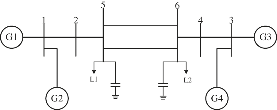
Figure 10: Single line diagram of two-area four-machine test system [12]
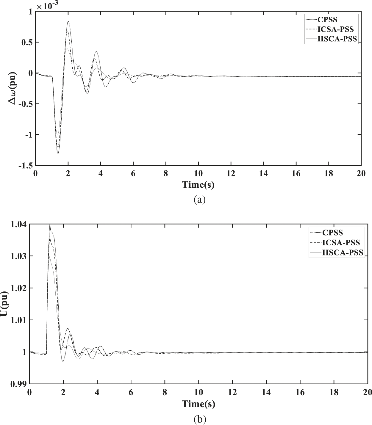
Figure 11: (a) Rotor speed deviation for +5% voltage reference value of generator G1. (b) Terminal voltage for +5% voltage reference value of generator G1

Figure 12: (a) Rotor speed deviation of the generator G1 for short circuit. (b)The terminal voltage of the generator G1 for the short circuit
5.5 Ten Machine Thirty-Nine Bus Power System
The 10 machines 39 bus system [40] in Fig. 13 is also widely used to test performance of PSS. Fig. 14 shows the dynamic response curves of generator G9 voltage reference value is decreased by 10% at 3 s. The terminal voltage of generator G9 decreased to 0.987 pu. The amplitude of generator G9 speed deviation of excitation system under traditional power system stabilizer (CPSS), power system stabilizer under basic immune clonal selection algorithm (ICSA-PSS), and power system stabilizer under improved immune clonal selection algorithm (IICSA-PSS) reached 0.036%, 0.029%, and 0.025%, respectively. It is clear from these figures that the IICSA-PSS provides better damping than the ICSA-PSS and conventional power system stabilizer. The settling times of generator G9 speed deviation of generator excitation system under traditional power system stabilizer (CPSS), power system stabilizer under ICSA (ICSA-PSS) and power system stabilizer under IICSA (IICSA-PSS) reached 18, 11, and 8.5 s, respectively. As shown in Fig. 15, generator G9 is shown a three-phase short-circuit fault at bus 29. The data shows that after the short-circuit fault occurred, the terminal voltage of generator G9 dropped to 0.4173 pu, and the deviation of generator speed reached 0.1798%. It is clear from these figures that the IICSA-PSS provides better damping performance than the ICSA-PSS and traditional power system stabilizer after the three-phase short-circuit fault. The settling times of generator G9 speed deviation of generator excitation system under traditional power system stabilizer (CPSS), power system stabilizer under ICSA (ICSA-PSS) and power system stabilizer under IICSA (IICSA-PSS) reached 16.5, 13, and 5 s, respectively. It is showing that the system having IICSA optimized power system stabilizer shows better performance than the system having ICSA optimized power system stabilizer and traditional power system stabilizer.
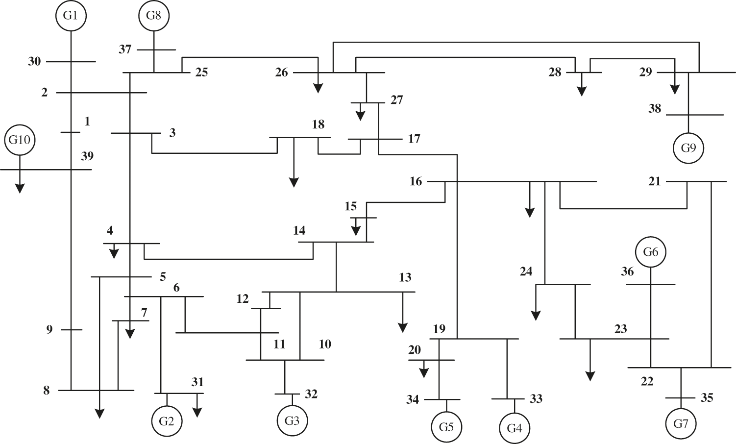
Figure 13: Single line diagram of ten machine thirty-nine bus test system [12]


Figure 14: (a) Rotor speed deviation of the −10% voltage reference value of generator G9. (b) The terminal voltage of the −10% voltage reference value of generator G9
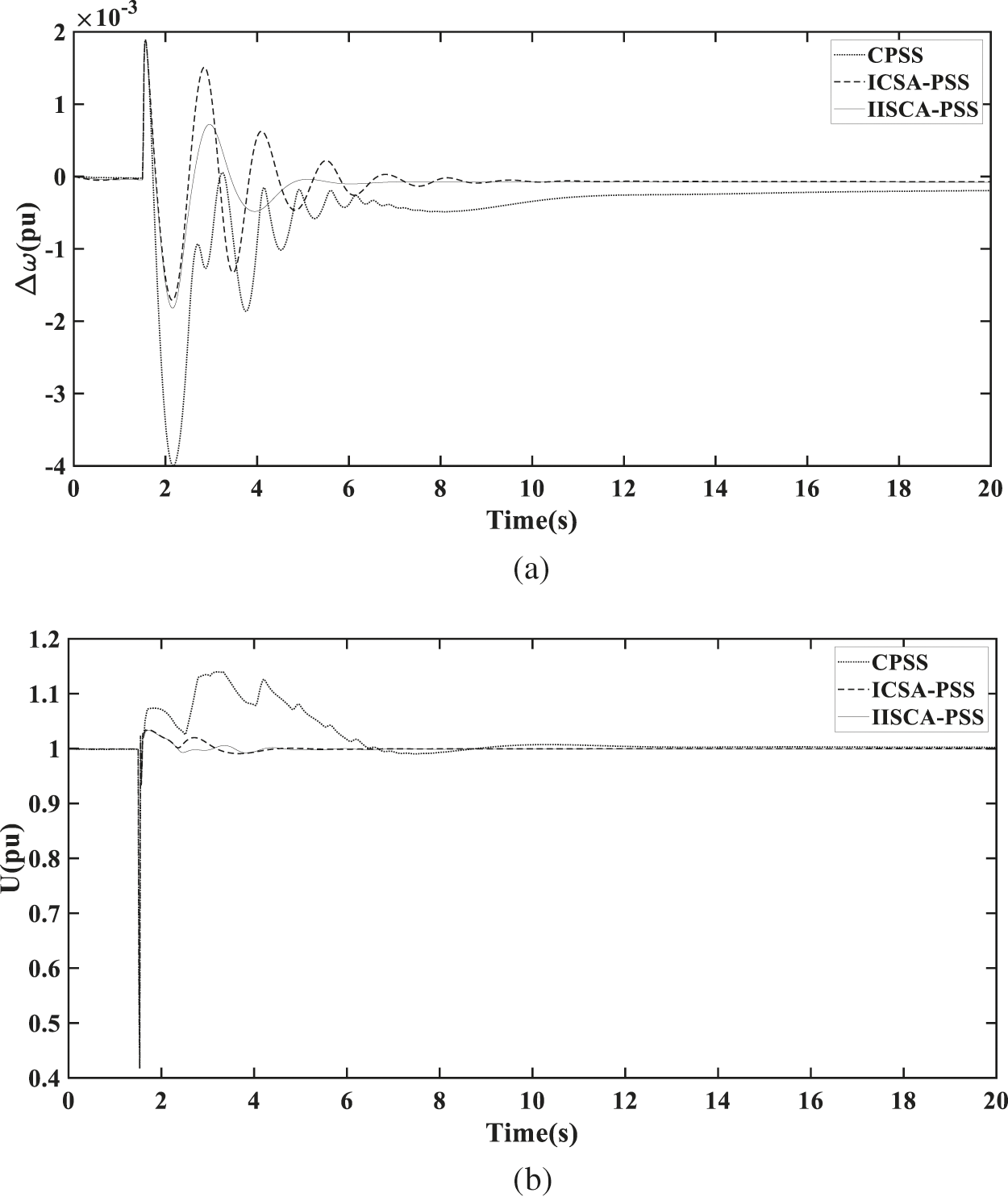
Figure 15: (a) Rotor speed deviation of G9 for short circuit. (b) The terminal voltage of G9 for short circuit
This work presented an improved immune clone selection algorithm to tune the parameters of the power system stabilizers for marine generator excitation control and then compared with a basic immune clone selection algorithm. The objective function is to minimize output deviation of the marine electric power system smaller and to ensure good dynamic performance and good stability when the low-frequency oscillations occur.
The proposed improved immune clone selection algorithm adopts adaptive excitation, vaccination, and adaptive mutation strategies. Then, the improved immune clone selection algorithm gets a smaller number of iterations and fast convergence rates to achieve the optimal parameters of the power system stabilizers than the basic immune clone selection algorithm, the salp swarm algorithm, and the grasshopper optimization algorithm. The final value is 0.1496 from the 21 iterations for the improved immune clone selection algorithm to optimize the parameters of the power system stabilizer.
The low-frequency oscillations caused by various load conditions disturbances and three-phase fault can be significantly suppressed better by installing power system stabilizers in the marine generators. The rotor speed deviation is 1.4% and the settling time is 1.3 after the short circuit of the marine generator for improved immune clone selection algorithm while the rotor speed deviation is 1.8% and the settling time is 1.9 for the basic immune clone selection algorithm. The simulation results show that the power system stabilizers optimized by an improved immune clone selection algorithm can greatly improve the stability and dynamic performance under various operating conditions and disturbances of the marine electric power system. Moreover, the proposed approach presents better performance than the basic immune clone selection algorithm to tune the parameters of power system stabilizers.
Future studies will be focused on the following two aspects:
(a) The proposed controller will be compared with a new control structure that hasn't been used for PSSs.
(b) To compare the performance of hybrid algorithms (immune clone selection algorithm and genetic algorithm) with a single algorithm to tune the parameters of power system stabilizers.
Funding Statement: This work is supported by Shanghai Science and Technology Planning Project (Project No. 20040501200).
Conflicts of Interest: The authors declare that they have no conflicts of interest to report regarding the present study.
1. Wu, J. C., Huo, C. X., Dang, J. (2018). Phase amplitude coordination optimization method for improving the gain of power system stabilizer. Automation of Electric Power Systems, 42(24), 203–212. DOI 10.7500/AEPS20180330001. [Google Scholar] [CrossRef]
2. Liu, Q. (2007). Power system stability and generator excitation control. Beijing: China Electric Power Press. [Google Scholar]
3. Chen, J., Jin, T., Zhu, X. Y., Li, Z. W. (2020). Parameter optimization of power system stabilizer based on SOGWO. Power System Protection and Control, 48(22), 159–164. [Google Scholar]
4. Wang, D. Y., Yan, W., Qiu, J. D. (2006). Optimization of power system stabilizer parameters based on genetic algorithm. Power Systems and Automation, 3, 59–63. [Google Scholar]
5. Zhao, F., Guo, C. L., Si, J. J. (2018). Optimization of PSS parameters based on bat algorithm. Control Engineering, 25(12), 2210–2218. DOI 10.14107/j.cnki.kzgc.161043. [Google Scholar] [CrossRef]
6. Zuo, J., Zhang, C. W., Xiao, Y. (2017). Optimal design of stabilizer parameters for multi-machine power system based on gray wolf optimization algorithm. Power Grid Technology, 41(9), 2987–2995. DOI 10.13335/j.1000-3673.pst.2017.0011. [Google Scholar] [CrossRef]
7. Fang, D. Z., Niu, W., Zhou, B. R. (2006). Coordinated design of power system stabilizer and controllable series compensator damping controller in multi-machine system. Journal of Tianjin University, 8, 895–900. [Google Scholar]
8. Gomes, S., Guimarães, C. H. C., Martins, N., Taranto, G. N. (2018). Damped Nyquist Plot for a pole placement design of power system stabilizers. Electric Power Systems Research, 158, 158–169. DOI 10.1016/j.epsr.2018.01.012. [Google Scholar] [CrossRef]
9. Mohandes, B., Abdelmagid, Y. L., Boiko, I. (2018). Development of PSS tuning rules using multi-objective optimization. International Journal of Electrical Power & Energy Systems, 100, 449–462. DOI 10.1016/j.ijepes.2018.01.041. [Google Scholar] [CrossRef]
10. Kahouli, O., Jebali, M., Alshammari, B., Abdallah, H. H. (2018). PSS design for damping low-frequency oscillations in a multi-machine power system with penetration of renewable power generations. IET Renewable Power Generation, 13, 116–127. DOI 10.1049/iet-rpg.2018.5204. [Google Scholar] [CrossRef]
11. Singh, M., Patel, R. N., Neema, D. D. (2019). Robust tuning of excitation controller for stability enhancement using multi-objective metaheuristic Firefly algorithm. Swarm and Evolutionary Computation, 44, 136–147. DOI 10.1016/j.swevo.2018.01.010. [Google Scholar] [CrossRef]
12. Rahmatian, M., Seyedtabaii, S. (2019). Multi-machine optimal power system stabilizers design based on system stability and nonlinearity indices using Hyper-Spherical Search method. International Journal of Electrical Power & Energy Systems, 105, 729–740. DOI 10.1016/j.ijepes.2018.09.024. [Google Scholar] [CrossRef]
13. Islam, N. N., Hannan, M. A., Shareef, H., Mohamed, A. (2017). An application of backtracking search algorithm in designing power system stabilizers for large multi-machine system. Neurocomputing, 237, 175–184. DOI 10.1016/j.neucom.2016.10.022. [Google Scholar] [CrossRef]
14. Miotto, E. L., de Araujo, P. B., Vargas, F., Gamino, E., Martins, B. L. F. (2018). Coordinated tuning of the parameters of PSS and POD controllers using bioinspired algorithms. IEEE Transactions on Industry Applications, 54, 334–341. DOI 10.1109/TIA.2018.2824249. [Google Scholar] [CrossRef]
15. Hemmati, R. (2018). Power system stabilizer design based on optimal model reference adaptive system. Neurocomputing, 9(2), 311–318. DOI 10.1016/j.asej.2016.03.002.f. [Google Scholar] [CrossRef]
16. Gurung, S., Naetiladdanon, S., Sangswang, A. (2019). Coordination of power-system stabilizers and battery energy-storage system controllers to improve probabilistic small-signal stability considering integration of renewable-energy resources. Applied Sciences, 9(6), 1109. DOI 10.3390/app9061109. [Google Scholar] [CrossRef]
17. Kang, R. D., Martinez, E. A., Viveros, E. C. (2020). Coordinated tuning of power system controllers using parallel genetic algorithms. Electric Power Systems Research, 190, 106628. DOI 10.1016/j.epsr.2020.106628. [Google Scholar] [CrossRef]
18. Liu, X. Y., He, Y. L., Li, X. M., Lu, P., Cheng, L. (2020). PSS parameter optimization based on comprehensive damping effect method aiming at actual grid characteristics in northern China. Mathematical Problems in Engineering, 2020, 5430289. DOI 10.1155/2020/5430289. [Google Scholar] [CrossRef]
19. Verdejo, H., Pino, V., Kliemann, W., Becker, C., Delpiano, J. (2020). Implementation of particle swarm optimization (PSO) algorithm for tuning of power system stabilizers in multimachine electric power systems. Energies, 13(8), 2093. DOI 10.3390/en13082093. [Google Scholar] [CrossRef]
20. Peres, W. (2019). Multi-band power oscillation damping controller for power system supported by static VAR compensator. Electrical Engineering, 101(3), 943–967. DOI 10.1007/s00202-019-00830-9. [Google Scholar] [CrossRef]
21. Baadji, B., Bentarzi, H., Bakdi, A. (2020). Comprehensive learning bat algorithm for optimal coordinated tuning of power system stabilizers and static VAR compensator in power systems. Engineering Optimization, 52(10), 1761–1779. DOI 10.1080/0305215X.2019.1677635. [Google Scholar] [CrossRef]
22. Guesmi, T., Farah, A., Abdallah, H. H., Ouali, A. (2018). Robust design of multimachine power system stabilizers based on improved non-dominated sorting genetic algorithms. Electrical Engineering, 100(3), 1351–1363. DOI 10.1007/s00202-017-0589-0. [Google Scholar] [CrossRef]
23. Ke, D. P., Chung, C. Y. (2016). Design of probabilistically-robust wide-area power system stabilizers to suppress inter-area oscillations of wind integrated power systems. IEEE Transactions on Power Systems, 31(6), 4297–4309. DOI 10.1109/TPWRS.2016.2514520. [Google Scholar] [CrossRef]
24. Liu, X. Y., He, Y. L., Yao, J. (2018). A new hybrid PSS optimization method based on improved active set algorithm. Mathematical Problems in Engineering, 2018, 4348257. DOI 10.1155/2018/4348257. [Google Scholar] [CrossRef]
25. Liu, Y., Wu, Q. H., Kang, H. T., Zhou, X. X. (2016). Switching power system stabilizer and its coordination for enhancement of multi-machine power system stability. CSEE Journal of Power and Energy Systems, 2(2), 98–106. DOI 10.17775/CSEEJPES.2016.00027. [Google Scholar] [CrossRef]
26. Alkhatib, H., Duveau, J. (2013). Dynamic genetic algorithms for robust design of multimachine power system stabilizers. International Journal of Electrical Power & Energy Systems, 45(1), 242–251. DOI 10.1016/j.ijepes.2012.08.080. [Google Scholar] [CrossRef]
27. Machowski, J., Bialek, J., Bumby, J. (2011). Power system dynamics: stability and control. UK: Wiley. [Google Scholar]
28. Chen, Z., Tang, H. R., Yan, S. X. (2019). Parameter design of wide-area power system stabilizer based on time-delay sensitivity and multi-objective optimization. Electric Power Automation Equipment, 39(10), 208–214. DOI 10.16081/j.epae.201910002. [Google Scholar] [CrossRef]
29. Pan, X. J., Zhang, L. W., Zhang, W. C. (2020). Parameter coordination optimization method for multi-operation power system stabilizers based on moth flame suppression optimization algorithm. Power Grid Technology, 44(8), 3038–3046. DOI 10.13335/j.1000-3673.pst.2019.1838. [Google Scholar] [CrossRef]
30. Jiang, C. X. S., Huang, P. W. (2020). A parameter tuning method for multi-frequency power system stabilizer considering multi-oscillation mode. Automation of Electric Power Systems, 44(4), 142–149. DOI 10.7500/AEPS20190117007. [Google Scholar] [CrossRef]
31. Khezri, R., Oshnoei, A., Yazdani, A. (2020). Intelligent coordinators for automatic voltage regulator and power system stabilizer in a multi-machine power system. IET Generation Transmission & Distribution, 14(23), 5480–5490. DOI 10.1049/iet-gtd.2020.0504. [Google Scholar] [CrossRef]
32. Sun, N. J., Wang, D. L., Wei, J. L. (2019). Optimal design of multi-machine PSS parameters based on SDM-prony and improved GWO algorithm. Power System Protection and Control, 47(10), 88–95. DOI 10.19783/j.cnki.pspc.180666. [Google Scholar] [CrossRef]
33. Wang, P. D., Chen, Y. J., Zhou, B. (2018). Two-stage coordinated optimization method for wide-area power system stabilizer parameters. Power System Protection and Control, 46(18), 25–32. DOI 10.7667/PSPC201834. [Google Scholar] [CrossRef]
34. Meng, Y. F., Wang, T., Li, Z. X. (2021). Improved adaptive artificial immune algorithm for function optimization problem. Beijing University of Aeronautics and Astronautics, 47(5), 894–903. DOI 10.13700/j.bh.1001-5965.2020.0058. [Google Scholar] [CrossRef]
35. Han, X. M., Wang, L. M. (2013). Improvement of artificial immune algorithm and its application. Beijing: Publishing House of Electronics Industry. [Google Scholar]
36. Saremi, S., Mirjalili, S., Lewis, A. (2017). Grasshopper optimization algorithm: Theory and application. Advances in Engineering Software, 105, 30–47. DOI 10.1016/j.advengsoft.2017.01.004. [Google Scholar] [CrossRef]
37. Dey, P., Saha, A., Bhattacharya, A., Marungsri, B. (2020). Analysis of the effects of PSS and renewable integration to an inter-area power network to improve small signal stability. Journal of Electrical Engineering & Technology, 15(5), 2057–2077. DOI 10.1007/s42835-020-00499-2. [Google Scholar] [CrossRef]
38. Ghazbi, S. N., Akbarzadeh, A., Kardan, I. (2018). Statistically optimized FOPID for output force control of SEAs. Advanced Robotics, 32(5), 231–241. DOI 10.1080/01691864.2018.1431150. [Google Scholar] [CrossRef]
39. Zhang, W., Shi, W. F., Zhuo, J. B. (2016). Quantum-PSO based system stabilizer optimization for shipboard power system. 2016 35th Chinese Control Conference (CCC), 2016, 9810–9814. DOI: 10.1109/ChiCC.2016.7554912. [Google Scholar] [CrossRef]
40. Kundur, P., Balu, N. J., Lauby, M. G. (1994). Power system stability and control. New York: McGraw-Hill. [Google Scholar]
 | This work is licensed under a Creative Commons Attribution 4.0 International License, which permits unrestricted use, distribution, and reproduction in any medium, provided the original work is properly cited. |